Sign In
Upload
Manuals
Brands
Kontron Manuals
Desktop
KBox B-202-CFL
User Manuals: Kontron KBox B-202-CFL Industrial PC
Manuals and User Guides for Kontron KBox B-202-CFL Industrial PC. We have
3
Kontron KBox B-202-CFL Industrial PC manuals available for free PDF download: User Manual
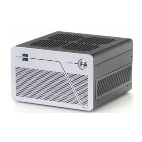
Kontron KBox B-202-CFL User Manual (84 pages)
Brand:
Kontron
| Category:
Desktop
| Size: 4 MB
Table of Contents
Symbols
6
For Your Safety
7
High Voltage Safety Instructions
7
Special Handling and Unpacking Instruction
7
Lithium Battery Precautions
8
General Instructions on Usage
8
Quality and Environmental Management
8
Disposal and Recycling
8
WEEE Compliance
8
Table of Contents
9
List of Tables
11
List of Figures
12
1 / General Safety Instructions
14
Electrostatic Discharge (ESD) Precautions
15
Grounding Methods
15
Instructions for the Lithium Battery
15
2 / Introduction
16
Figure 1: Kbox B-202-CFL
16
3 / Scope of Delivery
17
Packaging
17
Unpacking
17
Table 1: Scope of Delivery Kbox B-202-CFL Variants
17
Accessories
18
Table 2: Accessories
18
Product Identification Type Label
19
Figure 2: Type Labels
19
4 / Product Features
20
Front Side Features
20
Front Side Connectors
20
Power Button
20
USB 3.1 Gen 1 Port
20
Figure 3: Front Panel (Smart, Value and Smart Storage)
20
Rear Panel Features
21
Figure 4: Rear Panel (Smart, Value and Smart Storage Variants)
21
Figure 5: Rear Panel Kbox B-202-CFL Smart
21
Figure 6: Rear Panel Kbox B-202-CFL Value
22
Figure 7: Rear Panel Kbox B-202-Cfl Smart Storage
22
Rear Panel Connectors
23
Keyboard/Mouse PS/2 Connectors
23
USB 2.0 Ports
23
Display Port (DP)
23
DVI-D Connector
23
COM Port
24
LAN Ports
24
USB 3.1 Gen 2 Ports
24
USB 3.1 Gen 1 Ports
25
Line-IN, Line-OUT Connectors
25
DC-IN Connector
25
AC-IN (Option -Smart Storage Only)
25
Potential Equalization Stud
25
Wi-Fi Antenna Connectors (Option)
26
Figure 8: Wi-Fi Antenna
26
Left and Right Side Features
27
Figure 9: Left Side and Right Sid
27
Top Cover and Bottom Side Features
28
Figure 10: Top View
28
Figure 11: Bottom View
28
5 / Options
29
Expansion Options
29
Table 3: Kbox B-202-CFL Expansion Option
29
Drive Bay Options
30
Storage Bay Options
30
Table 4: Drive Bay Options
30
Figure 12: Drive Day Options
30
Figure 13: Storage Bay with Dual Removable 2.5" Ssds
30
Pcie Slot Options
31
Table 5: Storage Bay Options
31
Table 6: Expansion Slot Options
31
Figure 14: Expansion Slot
31
Internal Options
32
Table 7: On-Board Expansion Options
32
Power Options
33
Figure 15: Power Connections Options
33
6 / Accessing Components
34
Top Cover (Opening and Closing)
34
Figure 16: Holding Brackets
35
Installing and Removing an On-Board Mpcie Expansion Card
36
Installing and Removing an On-Board M.2 SSD Module
36
Drive Bay (Opening and Closing)
37
Figure 17: Drive Bay Cover Rear Side
37
Figure 18: Drive Bay Cover Top Side
37
Installing and Removing a 2.5" SSD Drive
38
Figure 19: External Drive Bay with 2.5" SSD Drive
38
Installing and Removing the 2.5" SSD Dual M.2 RAID Module
39
Figure 20: 2.5" SSD Dual RAID M.2 Module
39
Figure 21: Drive Bay with 2.5" SSD Dual M.2 RAID Module
40
Expansion Door (Opening and Closing)
42
Installing and Removing Pcie Expansion Cards
42
Figure 22: Pcie Expansion Card Screws
42
Figure 23: Removing Expansion Door
42
Figure 24: Pcie Slot Front Pin
43
Figure 25: Pcie Expansion Slot Holding Latch
43
Figure 26: Expansion Door
43
Storage Bay
44
Installing and Removing Storage Bay Drives
44
Figure 27: Storage Bay with Removable Drives
44
Figure 28: Storage Bay Tray
44
7 / Thermal Considerations
45
Active Cooling
45
Figure 29: Air-Intake Ventilation Openings
45
Figure 30: Air-Output Ventilation Openings
45
Mount Orientation
46
Minimum Clearance (Keep out Area)
46
Third Party Components
46
8 / Installation Instructions
47
Chassis Feet
48
Chassis Feet Mount (Option)
48
Figure 31: Position of Chassis Feet
48
Figure 32: Chassis Feet Mount Option
48
Mounting Brackets (Option)
49
Figure 33: Mounting Bracket
49
Figure 34: Keep out Areas - with Top Cover Facing the Mount Surface
50
Figure 35: Keep out Areas - with Bottom Side Facing the Mount Surface
50
Mounting on or Underneath a Desktop
51
Figure 36: Mounting Brackets on a Desktop/Mount Surface
51
Figure 37: Mounting Brackets -Underneath a Desktop/Mount Surface
51
Mounting on a Wall
52
Figure 38: Mounting Brackets Wall Mount Options with Bottom Side Facing the Mounting Surface
52
Figure 39: Mounting Brackets Wall Mount Options with Top Cover Facing the Mounting Surface
52
Connecting the Wi-Fi Antenna (Option)
53
9 / Starting up
54
Connecting the 12 VDC AC/DC Power Supply
54
Connecting the 24 VDC Wired Power Cable (Option)
54
Connecting to the AC Connector (Option)
55
Figure 40: 24 VDC Wired Power Cable
55
Power On/Off Procedure
56
Forced Shutdown
56
Operating System (OS) and Hardware Component Drivers
56
10 / Technical Data
57
Block Diagrams
57
Figure 41: Block Diagram of Kbox B-202-CFL Smart Variant Without Wi-Fi
57
Figure 42: Block Diagram of Kbox B-202-CFL Value Variant Without Wi-Fi
58
Technical Specification
59
Table 8: Motherboard Specification
59
Table 9: Processor Specification
59
Table 10: Storage Specification
59
Table 11: External Interface Specifications
60
Table 12: Internal Expansion Sockets
61
Table 13: External Expansion Slots
61
Table 14: Software Specification
61
Table 15: Chassis Specification
61
Mechanical Specification
62
Dimension Diagrams
62
Table 16: Mechanical Specifications
62
Figure 43: Dimensions Front Panel
62
Figure 44: Dimensions Rear Panel
62
Figure 45: Dimensions Top Cover
62
Figure 46: Dimensions Bottom Side
62
Environmental Specification
63
Table 17: Environmental Specification
63
Figure 47: Dimensions Right Side
63
Figure 48: Dimensions Left Side
63
Figure 49: Dimensions with Mounting Brackets
63
Directives and Standards
64
Table 18: Directives and Standards Compliance
64
Power Specification
65
DC-In, 12 VDC
65
Table 19: Power Supply 12 VDC AC/DC
65
DC-IN, 24 VDC (Option)
66
AC-IN (Option)
66
Power Protection
66
Table 20: Power Supply 24 VDC (Variant)
66
Table 21: Power Supply AC-IN (Variant)
66
Power Consumption
67
Potential Equalization
67
Table 22: Power Supply Protection Features (12 VDC and AC-IN)
67
Table 23: Power Consumption Estimation
67
11 / External Interface - Pin Assignments
68
DC-IN Power Connector Pin Assignment
68
USB 3.1 Gen 1 Port & USB 3.1 Gen 2 Pin Assignment
68
Table 24: DC Power Jack Pin Assignment
68
Table 25: USB 3.1 Connector Pin Assignment
68
USB 2.0 Port Pin Assignment
69
LAN Connector Pin Assignment
69
Table 26: USB 2.0 Connector Pin Assignment
69
Table 27: LAN (Gbe) Connector Pin Assignment
69
Table 28: LAN Link Activity
69
Display Port (DP) V1.2 Connector Pin Assignment
70
DVI-D Connector Pin Assignment
70
Table 29: Display Port (DP) Connector Pin Assignment
70
Table 30: DVI-D Connector Pin Assignment
70
PS/2 Keyboard Connector Pin Assignment
71
PS/2 Mouse Connector Pin Assignment
71
Audio Line-Out and Audio Line-In Connector Pin Assignment
71
Table 31: PS/2 Keyboard Connector Pin Assignment
71
Table 32: PS/2 Mouse Connector Pin Assignment
71
Table 33: Audio Line-OUT Audio Line-IN Pin Assignment
71
Serial Port Connector Pin Assignment
72
AC-IN Power Connector Pin Assignment (Option)
72
Table 34: Serial Interface COM Port (RS232) Connector Pin Assignment
72
12 / Bios
73
Starting the Uefi BIOS
73
BIOS Update
74
Table 35: Navigation Hot Keys Available in the Legend Bar
74
13 / Raid
75
Storage Bay RAID Array
75
Storage Bay RAID Configuration
75
Table 36: Storage Bay RAID Array
75
Figure 50: Kbox B-202-CFL Smart Storage RAID
75
Drive Bay RAID Array
76
Drive Bay RAID Configuration
76
Table 37: Drive Bay RAID
76
Table 38: RAID Module Jumper Settings
76
Figure 51: 2.5" SSD Dual RAID M.2 Module Settings
76
Drive Bay RAID Software
77
Table 39: S.M.A.R.T. Information Memory Attributes Examples
78
Table 40: Notifications Examples
78
Table 41: Event List Examples
78
Internal RAID Array
79
Internal RAID Array Configuration
79
Table 42: Internal RAID
79
14 / Technical Support
80
Returning Defective Merchandise
80
15 / Storage, Transportation and Maintenance
81
Storage
81
Transportation
81
Maintenance
81
Replacing the Lithium Battery
81
16 / Warranty
82
Limitation/Exemption from Warranty Obligation
82
List of Acronyms
83
Table 43: List of Acronyms
83
About Kontron
84
Advertisement
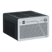
Kontron KBox B-202-CFL User Manual (77 pages)
Brand:
Kontron
| Category:
Desktop
| Size: 4 MB
Table of Contents
Symbols
6
For Your Safety
7
High Voltage Safety Instructions
7
Special Handling and Unpacking Instruction
7
Lithium Battery Precautions
8
General Instructions on Usage
8
Quality and Environmental Management
8
Disposal and Recycling
8
WEEE Compliance
8
Table of Contents
9
List of Tables
11
List of Figures
12
1 / General Safety Instructions for IT Equipment
13
Grounding Methods
15
2 / Introduction
16
Figure 1: Kbox B-202-CFL
16
3 / Scope of Delivery
17
Packaging
17
Type Label and Product Identification
17
Table 1: Scope of Delivery
17
Table 2: Accessories
17
Figure 2: Type Label
17
4 / Product Overview
18
Figure 3: Kbox B-202-CFL Overview
18
Front Panel View
19
Power-On Button
19
USB 3.1 Gen 1 Port
19
Figure 4: Front Panel
19
Rear Panel Views
20
Figure 5: Rear Panel Kbox B-202-CFL (Smart)
20
PS/2 Keyboard Connector
21
PS/2 Mouse Connector
21
USB 2.0 Ports
21
Figure 6: Rear Panal Kbox B-202-CFL (Value)
21
Display Port (DP)
22
DVI-D Connector
22
Serial Port (COM)
23
LAN Ports
23
USB 3.1 Gen 2 Ports
23
USB 3.1 Gen 1 Ports
23
Audio Connectors ( Line-IN, Line-OUT)
24
DC-IN Connector
24
Wi-Fi Antenna Connectors(Option)
24
Left and Right Side Views
25
Figure 7: Left Side and Right Side
25
Top Cover and Bottom Side Views
26
Figure 8: Top View
26
Figure 9: Bottom View
26
5 / System Expansion
27
System Expansion Combinations
27
Figure 10: System Expansion Options
27
Table 3: M.2 SSD Module and Mpcie Expansion Card Combinations
28
Table 4: Storage and Expansion Card Combinations
28
Mass Storage Devices
29
SSD Drive
29
SSD Dual M.2 RAID Module
29
Internal 2.5" SSD Drives
29
On-Board M.2 SSD Module
29
Expansion Cards
30
On-Board Mpcie Expansion Card
30
Pcie Expansion Cards
30
6 / Accessing Components
31
Removing and Installing the Top Cover
31
Removing the Top Cover
31
Installing the Top Cover
32
Figure 11: Top Cover Fastening Screws
32
Figure 12: Holding Brackets
32
Installing and Removing On-Board Mpcie Expansion Card
33
Installing and Removing the On-Board M.2 SSD Module
33
Installing and Removing Pcie Cards
34
Figure 13: Pcie Expansion Card Screws
34
Figure 14: Removing Pcie Expansion Card Door
34
Figure 15: Pcie Slot Front Pin
35
Figure 16: Pcie Expansion Slot Holding Latch
35
Figure 17: Pcie Expansion Card Door
35
Opening and Closing Drive Bay Cover
36
Figure 18: Drive Bay Cover Rear Side
36
Figure 19: Drive Bay Cover Top Side
36
Installing and Removing the Drive Bay 2.5" SSD Drive
37
Figure 20: Externally Accessible Drive Bay with 2.5" SSD Drive
37
Installing and Configuring the 2.5" SSD Dual M.2 RAID Module
38
Figure 21: 2.5" SSD DUAL RAID M.2 Module
38
Table 5: RAID Hardware Jumper Settings
39
Figure 22: Externally Accessible Drive Bay with 2.5" SSD Dual M.2 RAID Module
39
Replacing a M.2 SSD Module on the 2.5" SSD Dual M.2 RAID Module
40
7 / Thermal Considerations
41
Active Cooling
41
Figure 23: Air-Intake Ventilation Holes
41
Figure 24: Air-Output Ventilation Hole
41
Mount Orientation
42
Minimum System Clearance (Keep out Area)
42
Third Party Components
42
8 / Installation Instructions
43
Chassis Feet
44
Chassis Feet Mount (Option)
44
Figure 25: Position of Chassis Feet
44
Figure 26: Chassis Feet Mount Option
44
Mounting Brackets (Option)
45
Figure 27: Mounting Bracket
45
Figure 28: Keep out Areas - with Top Cover Facing the Mount Surface
46
Figure 29: Keep out Areas - with Bottom Side Facing the Mount Surface
46
Mounting Brackets on a Desktop
47
Figure 30: Mounting Brackets Desktop Mount Option
47
Figure 31: Mounting Brackets Underneath a Desktop Mount Option
47
Mounting Brackets on a Wall
48
Figure 32: Mounting Brackets Wall Mount Options with Bottom Side Facing the Mounting Surface
48
Figure 33: Mounting Brackets Wall Mount Options with Top Cover Facing the Mounting Surface
48
9 / Switching on
49
Connecting the Power Supply (PSU)
49
Switching on /Off
50
Operating System (OS) and Hardware Component Drivers
50
10 / Technical Data
51
Block Diagrams
51
Figure 34: Block Diagram of Kbox B-202-CFL Smart Variant Without Wi-Fi
51
Figure 35: Block Diagram of Kbox B-202-CFL Value Variant Without Wi-Fi
52
Technical Specification
53
Table 6: Mainboard Specification
53
Table 7: Processor Specification
53
Table 8: Storage Standard Configuration
53
Table 9: External Interface Specifications
54
Table 10: Internal Expansion Slots
54
Table 11: External Expansion Slots
54
Table 12: Software Specification
55
Table 13: Chassis Specification
55
Mechanical Specification
56
Dimension Diagrams - Kbox B-202-CFL
56
Table 14: Mechanical Specifications
56
Figure 36: Dimensions Front Panel
56
Figure 37: Dimensions Rear Panel
56
Figure 38: Dimensions Top Cover
57
Figure 39: Dimensions Bottom Side
57
Environmental Specification
58
Table 15: Environmental Specification
58
Figure 40: Dimensions Right Side
58
Figure 41: Dimensions Left Side
58
Figure 42: Dimensions with Mounting Brackets
58
Directives and Standards
59
Table 16: Directives and Standards Compliance for Kbox B-202-CFL
59
Power Specification
60
Power Consumption
60
Table 17: PSU 12V Electrical Specification
60
Table 18: Power Consumption
60
Power Protection
61
Ground
61
Table 19: PSU Power Protection Features
61
11 / External Interface - Pin Assignments
62
DC in Power Connector Pin Assignment
62
USB 3.1 Gen 1 Port & USB 3.1 Gen 2 Pin Assignment
62
Table 20: DC Power Jack Pin Assignment
62
Table 21: USB 3.1 Connector Pin Assignment
62
USB 2.0 Port Pin Assignment
63
LAN Gbe Connector Pin Assignment
63
Table 22: USB 2.0 Connector Pin Assignment
63
Table 23: LAN (Gbe) Connector Pin Assignment
63
Table 24: LAN Link Activity
63
Display Port (DP) V1.2 Connector Pin Assignment
64
DVI-D Connector Pin Assignment
64
Table 25: Display Port (DP) Connector Pin Assignment
64
Table 26: DVI-D Connector Pin Assignment
64
PS/2 Keyboard Connector Pin Assignment
65
PS/2 Mouse Connector Pin Assignment
65
Audio Line-Out and Audio Line-In Connector Pin Assignment
65
Table 27: PS/2 Keyboard Connector Pin Assignment
65
Table 28: PS/2 Mouse Connector Pin Assignment
65
Table 29: Audio Line-OUT Audio Line-IN Pin Assignment
65
Serial Port Connector Pin Assignment
66
Table 30: Serial Interface COM Port (RS232) Connector Pin Assignment
66
12 / Bios
67
Starting the Uefi BIOS
67
BIOS Update
68
Performing a BIOS Update
68
Table 31: Navigation Hot Keys Available in the Legend Bar
68
13 / Raid
70
Iraid Utility Software
70
RAID Settings Tab
70
Table 32: RAID Options
70
Table 33: S.M.A.R.T. Information Memory Attributes
70
Notification Tab
71
Event Tab
71
Chipset RAID
71
Table 34: Notification Tags
71
Table 35: Event List
71
14 Technical Support
72
Trouble Shooting
72
Table 36: Trouble Shooting Information
72
Returning Defective Merchandise
73
15 / Storage, Transportation and Maintenance
74
Storage
74
Transportation
74
Maintenance
74
Replacing Lithium Battery
74
16 / Warranty
75
Limitation/Exemption from Warranty Obligation
75
Appendix A: List of Acronyms
76
Table 37: List of Acronyms (Example)
76
About Kontron
77
Kontron KBox B-202-CFL User Manual (78 pages)
Brand:
Kontron
| Category:
Desktop
| Size: 4 MB
Table of Contents
Symbols
6
For Your Safety
7
High Voltage Safety Instructions
7
Special Handling and Unpacking Instruction
7
Lithium Battery Precautions
8
General Instructions on Usage
8
Quality and Environmental Management
8
Disposal and Recycling
8
WEEE Compliance
8
Table of Contents
9
List of Tables
11
List of Figures
12
1 / General Safety Instructions for IT Equipment
13
Electrostatic Discharge (ESD) Precautions
14
Grounding Methods
14
Instructions for the Lithium Battery
15
2 / Introduction
16
Figure 1: Kbox B-202-CFL
16
3 / Scope of Delivery
17
Packaging
17
Type Label and Product Identification
17
Table 1: Scope of Delivery
17
Table 2: Accessories
17
Figure 2: Type Labels
17
4 / Product Overview
18
Figure 3: Kbox B-202-CFL Overview
18
Front Side View
19
Front Connectors and Buttons
19
Figure 4: Front Panel
19
Rear Side Views
20
Figure 5: Rear Panel Kbox B-202-CFL (Smart)
20
Rear Panel Connectors
21
Figure 6: Rear Panal Kbox B-202-CFL (Value)
21
Left and Right Side Views
25
Figure 7: Left Side and Right Side
25
Top Cover and Bottom Side Views
26
Figure 8: Top View
26
Figure 9: Bottom View
26
5 / System Extension
27
System Storage and Expansion Card Combinations
27
Figure 10: System Expansion Options
27
Table 3: M.2 SSD Module and Mpcie Expansion Card Combinations
28
Table 4: Storage and Expansion Card Combinations
28
Mass Storage Devices
29
SSD Drive
29
SSD Dual M.2 RAID Module
29
Internal 2.5" SSD Drives
29
On-Board M.2 SSD Module
29
Expansion Cards
30
Pcie Expansion Cards
30
On-Board Mpcie Expansion Card
30
6 / Accessing Components
31
Removing and Installing the Top Cover
31
Figure 11: Top Cover Fastening Screws
32
Figure 12: Holding Brackets
32
Installing and Removing an On-Board Mpcie Expansion Card
33
Installing and Removing an On-Board M.2 SSD Module
33
Installing and Removing a Pcie Card
34
Figure 13: Pcie Expansion Card Screws
34
Figure 14: Removing Pcie Expansion Card Door
34
Figure 15: Pcie Slot Front Pin
35
Figure 16: Pcie Expansion Slot Holding Latch
35
Figure 17: Pcie Expansion Card Door
35
Opening and Closing the Drive Bay Cover
36
Figure 18: Drive Bay Cover Rear Side
36
Figure 19: Drive Bay Cover Top Side
36
Installing and Removing a 2.5" SSD Drive
37
Figure 20: External Drive Bay with 2.5" SSD Drive
37
Installing and Configuring the 2.5" SSD Dual M.2 RAID Module
38
Figure 21: 2.5" SSD Dual RAID M.2 Module
38
Table 5: RAID Module Jumper Settings
39
Replacing a M.2 SSD Module
40
Figure 22: External Drive Bay with 2.5" SSD Dual M.2 RAID Module
40
7 / Thermal Considerations
42
Active Cooling
42
Figure 23: Air-Intake Ventilation Holes
42
Figure 24: Air-Output Ventilation Holes
42
Mount Orientation
43
Minimum Clearance (Keep out Area)
43
Third Party Components
43
8 / Installation Instructions
44
Chassis Feet
45
Chassis Feet Mount (Option)
45
Figure 25: Position of Chassis Feet
45
Figure 26: Chassis Feet Mount Option
45
Mounting Brackets (Option)
46
Figure 27: Mounting Bracket
46
Figure 28: Keep out Areas - with Top Cover Facing the Mount Surface
47
Figure 29: Keep out Areas - with Bottom Side Facing the Mount Surface
47
Mounting Brackets on a Desktop
48
Figure 30: Mounting Brackets Desktop Mount Option
48
Figure 31: Mounting Brackets Underneath a Desktop Mount Option
48
Mounting Brackets on a Wall
49
Figure 32: Mounting Brackets Wall Mount Options with Bottom Side Facing the Mounting Surface
49
Figure 33: Mounting Brackets Wall Mount Options with Top Cover Facing the Mounting Surface
49
Connecting the Wi-Fi Antenna (Option)
50
9 / Starting up
51
Connecting to DC Power Supply
51
Switching on /Off
52
Operating System (OS) and Hardware Component Drivers
52
10 / Technical Data
53
Block Diagrams
53
Figure 34: Block Diagram of Kbox B-202-CFL Smart Variant Without Wi-Fi
53
Figure 35: Block Diagram of Kbox B-202-CFL Value Variant Without Wi-Fi
54
Technical Specification
55
Table 6: Mainboard Specification
55
Table 7: Processor Specification
55
Table 8: Storage Specification
55
Table 9: External Interface Specifications
56
Table 10: Internal Expansion Slots
56
Table 11: External Expansion Slots
57
Table 12: Software Specification
57
Table 13: Chassis Specification
57
Mechanical Specification
58
Dimension Diagrams
58
Table 14: Mechanical Specifications
58
Figure 36: Dimensions Front Panel
58
Figure 37: Dimensions Rear Panel
58
Figure 38: Dimensions Top Cover
59
Figure 39: Dimensions Bottom Side
59
Environmental Specification
60
Table 15: Environmental Specification
60
Figure 40: Dimensions Right Side
60
Figure 41: Dimensions Left Side
60
Figure 42: Dimensions with Mounting Brackets
60
Directives and Standards
61
Table 16: Directives and Standards Compliance
61
Power Specification
62
Power Consumption
62
Table 17: Power Supply Electrical Specification
62
Table 18: Power Consumption Estimation
62
Power Protection
63
Ground
63
Table 19: Power Supply Protection Features
63
11 / External Interface - Pin Assignments
64
DC in Power Connector Pin Assignment
64
USB 3.1 Gen 1 Port & USB 3.1 Gen 2 Pin Assignment
64
Table 20: DC Power Jack Pin Assignment
64
Table 21: USB 3.1 Connector Pin Assignment
64
USB 2.0 Port Pin Assignment
65
LAN Connector Pin Assignment
65
Table 22: USB 2.0 Connector Pin Assignment
65
Table 23: LAN (Gbe) Connector Pin Assignment
65
Table 24: LAN Link Activity
65
Display Port (DP) V1.2 Connector Pin Assignment
66
DVI-D Connector Pin Assignment
66
Table 25: Display Port (DP) Connector Pin Assignment
66
Table 26: DVI-D Connector Pin Assignment
66
PS/2 Keyboard Connector Pin Assignment
67
PS/2 Mouse Connector Pin Assignment
67
Audio Line-Out and Audio Line-In Connector Pin Assignment
67
Table 27: PS/2 Keyboard Connector Pin Assignment
67
Table 28: PS/2 Mouse Connector Pin Assignment
67
Table 29: Audio Line-OUT Audio Line-IN Pin Assignment
67
Serial Port Connector Pin Assignment
68
Table 30: Serial Interface COM Port (RS232) Connector Pin Assignment
68
12 / Bios
69
Starting the Uefi BIOS
69
BIOS Update
70
Performing a BIOS Update
70
Table 31: Navigation Hot Keys Available in the Legend Bar
70
13 / Raid
72
Iraid Utility Software
72
Settings
72
Table 32: RAID Options with Features
72
Table 33: S.M.A.R.T. Information Memory Attributes Examples
72
Notifications
73
Events
73
Chipset RAID
73
Table 34: Notifications Examples
73
Table 35: Event List Examples
73
14 / Technical Support
74
Returning Defective Merchandise
74
15 / Storage, Transportation and Maintenance
75
Storage
75
Transportation
75
Maintenance
75
Replacing the Lithium Battery
75
16 / Warranty
76
Limitation/Exemption from Warranty Obligation
76
Appendix A: List of Acronyms
77
Table 36: List of Acronyms
77
About Kontron
78
Advertisement
Advertisement
Related Products
Kontron KBox B-201-CFL
Kontron KBox B-101
Kontron KBox C-101
Kontron KBox E-200 Series
Kontron KBox A-201
Kontron KBox A-202
Kontron KBox M-100
Kontron KBox F-220 Series
Kontron KBox A-250
Kontron KBox A-150-APL
Kontron Categories
Computer Hardware
Motherboard
Server
Industrial PC
Desktop
More Kontron Manuals
Login
Sign In
OR
Sign in with Facebook
Sign in with Google
Upload manual
Upload from disk
Upload from URL