
Related Manuals for Kontron KBox A-250


Summary of Contents for Kontron KBox A-250
- Page 1 USER GUIDE KBox A-250 Doc. User Guide, Preliminary Rev. 0.6 Doc. ID: 1064-9561 www.kontron.com // 1...
- Page 2 KBox A-250 – User Guide, Preliminary Rev. 0.6 This page has been intentionally left blank www.kontron.com // 2...
- Page 3 In cases of doubt, please contact Kontron. This user guide is protected by copyright. All rights are reserved by Kontron. No part of this document may be reproduced, transmitted, transcribed, stored in a retrieval system, or translated into any language or computer language, in any form or by any means (electronic, mechanical, photocopying, recording, or otherwise), without the express written permission of Kontron.
- Page 4 ENVIRONMENTAL DAMAGE (COLLECTIVELY, "HIGH RISK APPLICATIONS"). You understand and agree that your use of Kontron devices as a component in High Risk Applications is entirely at your risk. To minimize the risks associated with your products and applications, you should provide adequate design and operating safeguards.
- Page 5 If you have any difficulties using this user guide, discover an error, or just want to provide some feedback, contact Kontron support. Detail any errors you find. We will correct the errors or problems as soon as possible and post the revised user guide on our website.
-
Page 6: Symbols
KBox A-250 – User Guide, Preliminary Rev. 0.6 Symbols The following symbols may be used in this user guide DANGER indicates a hazardous situation which, if not avoided, will result in death or serious injury. WARNING indicates a hazardous situation which, if not avoided, could result in death or serious injury. -
Page 7: For Your Safety
Therefore, in the interest of your own safety and of the correct operation of your new Kontron product, you are requested to conform with the following guidelines. -
Page 8: Lithium Battery Precautions
General Instructions on Usage In order to maintain Kontron’s product warranty, this product must not be altered or modified in any way. Changes or modifications to the product, that are not explicitly approved by Kontron and described in this user guide or received from Kontron Support as a special handling instruction, will void your warranty. -
Page 9: Table Of Contents
4.8.1. Rear Side View of the KBox A-250 with Vertical Mounting Bracket ..................25 4.8.2. Rear Side View of the KBox A-250 as Desktop with Rubber Feet ..................26 4.8.3. Rear Side View of the KBox A-250 with Wallmount Brackets ....................26 4.9. - Page 10 9.1. Mechanical Specifications ..................................37 9.1.1. Mechanical Specifications of the KBox A-250 as Desktop ...................... 37 9.1.2. Mechanical Specifications of the KBox A-250 with Vertical Mounting Plate ..............38 9.1.3. Mechanical Specifications of the KBox A-250 Wall/Table Mounting Brackets .............. 39 9.2.
-
Page 11: List Of Tables
Figure 16: Restricted area for mounting around KBox A-250 (desktop side view with antenna) ........30 Figure 17: Restricted area for mounting around KBox A-250 (front view with vert./horiz. mounting brakets) ....31 Figure 18: Power plug terminal ................................... 32 Figure 19: Dimensions: Front as desktop .............................. -
Page 12: 1/ General Safety Instructions For It Equipment
Kontron is exempt from accident liability, this also applies during the warranty period. The product has been built and tested according to the basic safety requirements for low voltage (LVD) applications and has left the manufacturer in safety-related, flawless condition. - Page 13 KBox A-250 – User Guide, Preliminary Rev. 0.6 Additional safety instructions for DC power supply circuits To guarantee safe operation of devices with DC power supply voltages larger than 60 volts DC or a power consumption larger than 240 VA, please observe that: ...
-
Page 14: Electrostatic Discharge (Esd)
KBox A-250 – User Guide, Preliminary Rev. 0.6 1.1. Electrostatic Discharge (ESD) A sudden discharge of electrostatic electricity can destroy static-sensitive devices or micro- circuitry. Therefore proper packaging and grounding techniques are necessary precautions to prevent damage. Always take the following precautions: Transport boards in ESD-safe containers such as boxes or bags. -
Page 15: 2/ Electromagnetic Compatibility
KBox A-250 – User Guide, Preliminary Rev. 0.6 2/ Electromagnetic Compatibility For detailed information refer to section 9.3 “CE Directives and Standards”. 2.1. Electromagnetic Compatibility (EU) This product is intended only for use in industrial areas. The most recent version of the EMC guidelines (EMC Directive 2014/30/EU) and/or the German EMC laws apply. -
Page 16: 3/ Shipment And Unpacking
Mini PCIe WiFI card (always factory-installed if orderd) with two antennas (enclosed) KBox A-250 can optionally be ordered with a factory-installed SSD Kit (mSAta [instead of WiFi] and/or M.2) Mini PCIe LTE card (always factory-installed if orderd) with two antennas (enclosed) SD card ... -
Page 17: Type Label And Product Identification
KBox A-250 – User Guide, Preliminary Rev. 0.6 3.3. Type Label and Product Identification The type label (product name, serial number) of your KBox A-250 system are located on the bottom side of the device (refer to Figure 1 and Figure 7 pos. 1). -
Page 18: 4/ System Overview
IoT edge applications. For local data collection, e.g. link to sensor and machine level, it offers one serial port (RS232).The KBox A-250 is one of the first Kontron products which is Microsoft® Azure certified. This means the hardware is tested and verified and can be integrated into Microsoft®... -
Page 19: Rtc
KBox A-250 – User Guide, Preliminary Rev. 0.6 4.1. RTC The KBox A-250 comprises a chipset internal RTC. To provide a valid date and time when no power is connected to the KBox A-250, the RTC is buffered by the CMOS battery. -
Page 20: Block Diagram Of The Kbox A-250
KBox A-250 – User Guide, Preliminary Rev. 0.6 4.3. Block Diagram of the KBox A-250 Figure 2: Block Diagram of the KBox A-250 www.kontron.com // 20... -
Page 21: Front Side
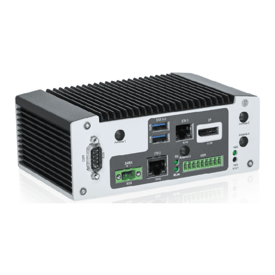
KBox A-250 – User Guide, Preliminary Rev. 0.6 4.4. Front Side Figure 3: KBox A-250 – Front View Antenna 4 (LTE) Antenna 2 (WLAN) Power LED Power/Reset Button X109 DisplayPort GPIO X102 ETH 1 Antenna 3 (LTE) SSD/WLAN X105, X106 LEDs USB 3.0... -
Page 22: Front Interfaces Of The Kbox A-250
4.5. Front Interfaces of the KBox A-250 101 - Power Input Connector The 2-pin connector (X101, Figure 3) provides the power connection of the KBox A-250 to the appropriate DC main power supply. For pin assignments refer to the subsection 10.1.1. -
Page 23: X102/X103 - Ethernet Connectors (Eth)
For pin assignment refer to subsection 10.1.2. 4.5.3. X105/X106 - USB 3.0 The KBox A-250 provides two USB 3.0 interfaces. This connectors (X105, X106, Figure 3) allows connection of USB 3.0 or USB 2.0 compatible devices to the system. For pin assignment refer to subsection 10.1.3. -
Page 24: Left And Right Side View
Figure 9: Top side of the KBox A-250 system Figure 10: Bottom side of the KBox A-250 system To provide sufficient heat dissipation for the cooling of the KBox A-250 platform, never cover the cooling fins of the chassis. Do not place any objects onto the device. -
Page 25: Rear Side View
4.8.1. Rear Side View of the KBox A-250 with Vertical Mounting Bracket The KBox A-250 is designed for wall mounting, in vertical position inside of a control cabinet or as desktop. Please observe the mounting instructions included in the section 6/ “Installation Instructions”, and the outline dimensions in the subsection 9.1.2 “Mechanical Specifications of the KBox A-250 with Vertical Mounting Plate”. -
Page 26: Rear Side View Of The Kbox A-250 As Desktop With Rubber Feet
KBox A-250 – User Guide, Preliminary Rev. 0.6 4.8.2. Rear Side View of the KBox A-250 as Desktop with Rubber Feet Figure 12: Rear side of the KBox A-250 (shown as desktop unit) 4.8.3. Rear Side View of the KBox A-250 with Wallmount Brackets... -
Page 27: Optional Parts
4.9.1. DIN Rail Clip (Option) For DIN Rail mounting of the KBox A-250 a DIN Rail clip can be ordered (refer to subsection 3.2.2 “Optional Parts”). If ordered, you can adopt your system for mounting to a DIN rail. Tapped holes are provided on the access cover (Figure 7, pos. -
Page 28: 5/ Thermal Considerations
The applied cooling method provides adequate cooling of the device during operation and performs a one-way thermal transfer to the chassis. Three sides of the KBox A-250 consist of a compact aluminum U-shaped chassis are with cooling fins. The cooling fins provide heat dissipation during operation. -
Page 29: 6/ Installation Instructions
Figure 17. Refer also to section 9.1.2 “Mechanical Specifications”. The KBox A-250 must be firmly attached to a clean flat and solid mounting surface. Use proper fastening materials suitable for the mounting surface. Ensure that the mounting surface type and the used mounting solution safely support the load of the KBox A-250 and the attached components. -
Page 30: System Mounting
The key holes of the vertical mounting plate (Figure 11, pos. 2) allow you to mount the KBox A-250 inside the control cabinet in vertical position. The key holes of the mounting brackets (Figure 11, pos. 2) allow you to mount the KBox A-250 to a wall or table in vertical as well as in horizontal position. -
Page 31: Figure 17: Restricted Area For Mounting Around Kbox A-250 (Front View With Vert./Horiz. Mounting Brakets)
KBox A-250 – User Guide, Preliminary Rev. 0.6 Figure 17: Restricted area for mounting around KBox A-250 (front view with vert./horiz. mounting brakets) KEEP OUT AREA (air circulation) www.kontron.com // 31... -
Page 32: Dc Power Connection
KBox A-250 – User Guide, Preliminary Rev. 0.6 6.2. DC Power Connection The KBox A-250 is connected by a power plug terminal (“TE Connectivity 796859-2”) connector to a DC power source via a DC power supply wiring (only the power plug terminal is included). -
Page 33: 7/ Starting Up
7.1. Connecting to DC Main Power Supply The DC input connector (Figure 3 and Figure 4, marked X101) is located on the front side of the KBox A-250. The KBox A-250 will be connected to a DC main power supply via the supplied power plug terminal (see Figure 18) and corresponding power wires (not included). -
Page 34: Operating System And Hardware Component Drivers
You can download this document from our web site www.kontron.com by selecting Product/ Downloads tab/Windows. If you have ordered The KBox A-250 without a pre-installed operating system, you will need to install the operating system and the appropriate drivers for the system configuration you have ordered (optional hardware components) yourself. -
Page 35: 8/ Maintenance And Cleaning
KBox A-250 – User Guide, Preliminary Rev. 0.6 8/ Maintenance and Cleaning Equipment from Kontron requires only minimum servicing and maintenance for proper operation. For light soiling, clean the KBox A-250 with a dry cloth. Carefully remove dust from the surface of the cooling fins of the chassis using a clean, soft brush. -
Page 36: 9/ Technical Specifications
KBox A-250 – User Guide, Preliminary Rev. 0.6 9/ Technical Specifications Table 1: Technical Specifications KBox A-250 Installed Module and Baseboard with pITX SBC Baseboard Intel Atom® x5-E3930/E3940/E3950 up to 8 GB DDR3L BIOS AMI® BIOS Interfaces 1x Ethernet (10/100 Mbit/s) -
Page 37: Mechanical Specifications
Chassis: steel sheet, light grey (RAL 7035) Side with External Interfaces : trim strips, traffic grey (RAL 7043) 9.1.1. Mechanical Specifications of the KBox A-250 as Desktop Figure 19: Dimensions: Front as desktop Figure 20: Dimensions: Front side with antennas and wall/table mounting brackets www.kontron.com... -
Page 38: Mechanical Specifications Of The Kbox A-250 With Vertical Mounting Plate
KBox A-250 – User Guide, Preliminary Rev. 0.6 9.1.2. Mechanical Specifications of the KBox A-250 with Vertical Mounting Plate Figure 21: Dimensions: Left side Figure 22: Dimensions: Rear side with vertical mounting plate 99.5 Figure 23: Dimensions: Detail key hole www.kontron.com... -
Page 39: Mechanical Specifications Of The Kbox A-250 Wall/Table Mounting Brackets
KBox A-250 – User Guide, Preliminary Rev. 0.6 9.1.3. Mechanical Specifications of the KBox A-250 Wall/Table Mounting Brackets Figure 24: Dimensions: Top side (with wall/table mounting brackets) Figure 25: Dimensions: front side (with wall/table mounting brackets) 24VDC Figure 26: Detail mounting slide hole (wall/table mounting brackets) www.kontron.com... -
Page 40: Environmental Specifications
KBox A-250 – User Guide, Preliminary Rev. 0.6 9.2. Environmental Specifications Table 3: Environmental Specifications KBox A-250 (Standard Version) Thermal Management Fanless cooling Operating Temperature 0°C … +40°C (32 … 104°F) Storage / Transit Temperature -40°C … +85°C (-40°F … +185°F) Relative Humidity (Operating/Transit) 93 % @ 40 °C (non-condensing) acc. -
Page 41: Ce Directives And Standards
KBox A-250 – User Guide, Preliminary Rev. 0.6 9.3. CE Directives and Standards Table 4: CE Directives and Standards CE-Mark Electromagnetic Directive 2014/30/EU Compatibility Compliant with EU Low Voltage Directive 2014/35/EU Directives Radio Equipment Directive 2014/53/EU Directive (RED) RoHS II... -
Page 42: 10/ Standard Interfaces - Pin Assignments
KBox A-250 – User Guide, Preliminary Rev. 0.6 Standard Interfaces – Pin Assignments Low-active signals are indicated by a minus sign. 10.1.1. (X101) Power Input Connector Table 5: (X101) Power Input Connector Signal Name 2-pin POWER SUBCON (male) +24 VDC (input) 0V (input ) 10.1.2. -
Page 43: X105, X106) Usb 3.0 Ports
KBox A-250 – User Guide, Preliminary Rev. 0.6 10.1.3. (X105, X106) USB 3.0 Ports Table 7: (X105, X106) USB 3.0 Port Signal Name Signal Name 9-pin USB Connector Type A Version 3.0/2.0 USB 2.0 contact pins USB 3.0 contact pins VCC, fused (900 mA max.) -
Page 44: X110) Serial Interface Com 1 (Rs232)
The maximum GPIO input voltage must not exceed the current operating voltage of the KBox A-250 (e.g., when the KBox A-250 is operated with 22 V, the voltage applied to the GPIO pins must not exceed 22 V). www.kontron.com... -
Page 45: 11/ Uefi Bios
11/ uEFI BIOS 11.1. Starting the uEFI BIOS The pITX-APL is provided with a Kontron-customized, pre-installed and configured version of American Megatrends, Inc. (AMI). It is based on the Unified Extensible Firmware Interface (uEFI) specification and the Intel® Platform Innovation Framework for EFI. This uEFI BIOS provides a variety of new and enhanced functions specifically tailored to the hardware features of the pITX-APL. -
Page 46: Setup Menus
KBox A-250 – User Guide, Preliminary Rev. 0.6 11.2. Setup Menus The Setup utility features a selection bar at the top of the screen that lists the available menus: Main Advanced Chipset Security Boot ... -
Page 47: Table 12: Main Setup Menu Sub-Screens
KBox A-250 – User Guide, Preliminary Rev. 0.6 Table 12: Main Setup Menu Sub-screens Sub-Screen Function Second level Sub-Screen / Description Read only field BIOS Displays BIOS Information Information Board Vendor, BIOS Version, Build Date and Time, Access Level Read only field... -
Page 48: Advanced Setup Menu
KBox A-250 – User Guide, Preliminary Rev. 0.6 11.2.2. Advanced Setup Menu The Advanced Setup menu provides sub-screens and second level sub-screens with functions, for advanced configuration and Kontron specific configurations. Setting items, on this screen, to incorrect values may cause system malfunctions. -
Page 49: Table 13: Advanced Setup Menu Sub-Screens And Functions
KBox A-250 – User Guide, Preliminary Rev. 0.6 Table 13: Advanced Setup menu Sub-screens and Functions Sub-Screen Function Second level Sub-Screen / Description Intel® PRO/1000 7.0.06 PCI-E Driver Health When set to Enable: Active PCR banks Available PCR banks SHA-1 PCR Bank [Enabled]... - Page 50 KBox A-250 – User Guide, Preliminary Rev. 0.6 Sub-Screen Function Second level Sub-Screen / Description Parity [None] Stop Bits [1] Turbo Mode [Enabled] Intel Virtualization Technology [Enabled] Configuration VT-d [Disabled] Monitor Mwait [Disabled] Intel ® Graphics Controller AMI Graphic Output Intel ®...
- Page 51 KBox A-250 – User Guide, Preliminary Rev. 0.6 Sub-Screen Function Second level Sub-Screen / Description When set to Enabled: Panel Type [Standard] Resolution [1024 x 768] Panel Color Depth [24-Bit VESA] Panel Voltage [3.3V] Channel [Dual] LVDS LVDS Flat Panel Display...
- Page 52 KBox A-250 – User Guide, Preliminary Rev. 0.6 Sub-Screen Function Second level Sub-Screen / Description DDR SSC Bending Selection Table [0% (No Clock Bending)] When set to Enable: HighSpeed SerialIO SSC [Enable] HighSpeed SerialIO SSC Selection Table [-0.5%] Kernel Debugger Configuration...
-
Page 53: Chipset Setup Menu
KBox A-250 – User Guide, Preliminary Rev. 0.6 Sub-Screen Function Second level Sub-Screen / Description Punit Message Level [LEVEL LOW] PMC Message Level [LEVEL LOW] Native PCIE Enable [Enable] RC ACPI Settings Native ASPM [Enable] RTD3 Settings RTD3 Support [Disable] 11.2.3. - Page 54 KBox A-250 – User Guide, Preliminary Rev. 0.6 Sub-Screen Function Second level Sub-Screen / Description PCI Clock Run [Enable] Real Time Option [RT Disable] GOP Configuration Uncore GOP Driver [Enable] Configuration Intel Graphics Pei Display PEIM [Disable] GOP Brightness Level [140]...
- Page 55 KBox A-250 – User Guide, Preliminary Rev. 0.6 Sub-Screen Function Second level Sub-Screen / Description Non Snoop Latency Override [Auto] PCIE LTR Lock [Disable] PCIE Selectable De-emphasis [Enable] SATA Drives Chipset-SATA Controller Configuration SATA Port 0 Port 0 [Enable] SATA Port 0 Hot Plug Capability [Disable]...
-
Page 56: Security Setup Menu
KBox A-250 – User Guide, Preliminary Rev. 0.6 11.2.4. Security Setup Menu The Security Setup menu provides information about the passwords and functions for specifying the security settings. The passwords are case-sensitive. Figure 30: Security Setup Menu Initial Screen The following table shows Security sub-screens and functions. - Page 57 KBox A-250 – User Guide, Preliminary Rev. 0.6 Function Description page https://www.kontron.com/products/solutions/security/sec- line.html for more information. Key Management Enables expert users to modify Secure Boot Policy Variables without full authentication. If only the administrator’s password is set, then only access to the setup is limited and is requested when entering the setup.
-
Page 58: Boot Setup Menu
KBox A-250 – User Guide, Preliminary Rev. 0.6 11.2.5. Boot Setup Menu The Boot Setup menu lists dynamically generated boot device priority order. Figure 31: Boot Setup Menu Initial Screen The following table shows Boot sub-screens and functions, and describes the content. Default settings are in bold. - Page 59 KBox A-250 – User Guide, Preliminary Rev. 0.6 Function Description PS2 Support Network Stack Driver Support Redirection Support New Boot Option Policy Controls the placement of newly detected UEFI boot options Hard Drive BBS Priotities Sets the placement of legacy boot options www.kontron.com...
-
Page 60: Exit Setup Menu
KBox A-250 – User Guide, Preliminary Rev. 0.6 11.2.6. Exit Setup Menu The Save and Exit Setup menu provides functions for handling changes made to the uEFI BIOS settings and exiting the Setup program. If system cannot boot or work properly due to incorrect setting, shorting Pin-1 and Pin-2 on J15 jumper will load the default setting of BIOS upon power cycle. -
Page 61: The Uefi Shell
11.3. The uEFI Shell The Kontron uEFI BIOS features a built-in and enhanced version of the uEFI Shell. For a detailed description of the available standard shell scripting, refer to the EFI Shell User Guide. For a detailed description of the available standard shell commands, refer to the EFI Shell Command Manual. -
Page 62: Uefi Shell Scripting
Initially searches for Kontron flash-stored startup script. If there is no Kontron flash-stored startup script present then the uEFI-specified startup.nsh script is used. This script must be located on the root of any of the attached FAT formatted disk drive. - Page 63 KBox A-250 – User Guide, Preliminary Rev. 0.6 Start flash.nsh or flash_with_fpt.nsh (if available) OR type fpt –y –f pITX_APL_BIOS_Ver_<xxx>……bin Wait until flashing is successful and then power cycle the board. Do not switch off the power during the flash process! www.kontron.com...
-
Page 64: Appendix A: List Of Acronyms
KBox A-250 – User Guide, Preliminary Rev. 0.6 Appendix A: List of Acronyms Table 18: List of Acronyms (Example) Application Programming Interface Base Management Controller Command-Line Interface Computer-on-Module Error Checking and Correction Field Replaceable Unit Graphics Processing Unit HD/HDD Hard Disk /Drive... -
Page 65: About Kontron
KBox A-250 – User Guide, Preliminary Rev. 0.6 About Kontron Kontron is a global leader in embedded computing technology (ECT). As a part of technology group S&T, Kontron offers a combined portfolio of secure hardware, middleware and services for Internet of Things (IoT) and Industry 4.0 applications.
Need help?
Do you have a question about the KBox A-250 and is the answer not in the manual?
Questions and answers