Siemens MAG 1100 F Operating Instructions Manual
Electromagnetic flowmeters
Hide thumbs
Also See for MAG 1100 F:
- Instructions manual (28 pages) ,
- Operating instructions manual (75 pages) ,
- Quick start manual (16 pages)
Table of Contents
Advertisement
Quick Links
Advertisement
Table of Contents

Related Manuals for Siemens MAG 1100 F


Summary of Contents for Siemens MAG 1100 F
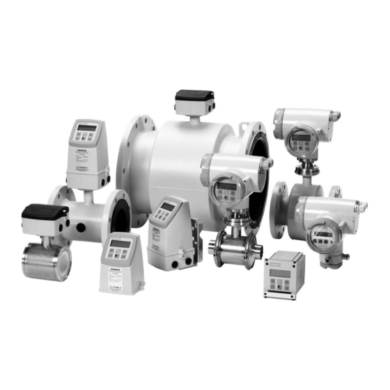
- Page 2 SITRANS F M Siemens Flow Instruments MAG 1100 MAG 1100 F MAG 3100 MAG 3100 P MAG 5100 W range of electromagnetic flowmeters Size [mm/inch] DN 2 ... 100/ DN 10 ... 100/ DN 15 ... 2000/ DN 15 ... 300/ DN 25 ...
-
Page 3: Table Of Contents
Output characteristics MAG 5000 and MAG 6000 ....................21 2.8.1 Conductivity of medium and sensor cables ......................22 2.8.2 Cable requirements ..............................22 Cable data (Supplied by Siemens Flow Instruments) .................... 22 3.1.1 Sizing table (DN 2 to DN 2000) ..........................23 3. Project guidance 3.1.2 Sizing table ( ... - Page 4 Under the Pressure Equipment Directive this product is a pressure accessory, and not approved for use as a safety accessory, as defined by the Pressure Equipment Directive. Removal of the terminal box except by Siemens Flow Instruments or their approved agents will invalidate the PED conformity of the product.
-
Page 5: Product Introduction
⇒ Simple to commission ⇒ Simple to operate ⇒ Simple to maintain SITRANS F M electromagnetic flowmeters are manufactured by Siemens Flow Instruments A/S - one of the world's leading manufacturers of flowmeters. All SITRANS F M electromagnetic flowmeters feature a unique SENSORPROM memory unit ®... -
Page 6: Mode Of Operation
U i = k x v, the electrode signal is directly proportional to the fluid velocity A flowmeter consists of a sensor (MAG 1100, MAG 1100 F, MAG 3100, MAG 3100 P or MAG 5100 W) and a transmitter (MAG 5000 or 6000). -
Page 7: Pressure Equipment Directive 97/23Ecs
Since 30 May 2002 the "Pressure Equipment Directive" is mandatory for all pressure equipment Pressure Equipment sold within the EU and EFTA. Directive 97/23EC Siemens Flow Instruments products confirms to PED by following the tables below. MAG 5100 W (7ME6580 only < DN600 (< 24")) Flange PN 10... -
Page 8: Exclusions
EXC.PED EXC.PED EXC.PED EXC.PED EXC.PED Siemens Flow Instruments products confirms to PED by following the tables below. The key to the tables is as follows. Excluded from PED under SEP or LVD EXC. PED Product covered by PED Product covered by PED but available conforming or non conforming to PED... -
Page 9: Technical Data
SITRANS F M 2. Technical data MAG 1100 and MAG 1100 Ex Technical data 2.1 Sensor MAG 1100 and MAG 1100 HT (High temperature) Type MAG 1100 MAG 1100 HT (High temperature) Measuring principle Electromagnetic induction Excitation frequency DN 2 ... 65 ( "... - Page 10 SITRANS F M 2. Technical data Type MAG 1100 MAG 1100 HT (High temperature) Enclosure rating IP67 to EN 60529 (NEMA 4X), 1 mH O for 30 min 89/336 EEC Design Weight See dimensional drawings See dimensional drawings Material • Enclosure - MAG 1100 Stainless steel AISI 316L (1.4404) Stainless steel AISI 316L (1.4404)
-
Page 11: Sensor Mag 1100 F
SITRANS F M 2. Technical data 2.2 Sensor MAG 1100 F Type MAG 1100 F Measuring principle Electromagnetic induction Excitation frequency DN 10 ... 65 (¼" … 2½"): 12.5 Hz / 15 Hz (Main supply: 50 Hz / 60 Hz) DN 80 ... - Page 12 Adapter Stainless steel AISI 316/Stainless steel AISI 304 (ISO 2852) Gasket • MAG 1100 F (Ceramic) FKM/FPM with stainless steel insert (AISI 304) (-20 ... +150 °C (-4 ... +302 °F)) EPDM (-20 ... +150 °C (-4 ... +302 °F)) •...
-
Page 13: Sensor Mag 3100
MAG 3100, MAG 3100 HT and MAG 3100 P SITRANS F M 2. Technical data 2.3 Sensor MAG 3100, MAG 3100 HT and MAG 3100 P Type MAG 3100 MAG 3100 HT (High Temperature) MAG 3100 P Nominal size DN 15 ... DN 2000 (½"... -
Page 14: Transmitter Mag 6000
SITRANS F M 2. Technical data MAG 3100, MAG 3100 HT and MAG 3100 P 2.3 Sensor MAG 3100, MAG 3100 HT and MAG 3100 P (continued) Type MAG 3100 MAG 3100 HT (High Temperature) MAG 3100 P Operating pressure Operating pressure •... - Page 15 MAG 3100, MAG 3100 HT and MAG 3100 P SITRANS F M 2. Technical data 2.3 Sensor MAG 3100, MAG 3100 HT and MAG 3100 P (continued) Design (continued) Type MAG 3100 MAG 3100 HT (High Temperature) MAG 3100 P Electrode material •...
-
Page 16: Sensor Mag 5100 W
SITRANS F M 2. Technical data MAG 5100 W 2.4 Sensor MAG 5100 W Technical specifications EPDM or NBR lining (Order No. 7ME6520) Ebonite lining (Order No. 7ME6580) Product characteristic: Targeted towards the EU water markets and Targeted towards the Non EU water markets low flow applications: Design and nominal size Full bore sensor: DN 25 ... -
Page 17: Transmitter Mag 5000
SITRANS F M 2. Technical data MAG 5000 and MAG 6000 2.4 Sensor MAG 5100 W (continued) Technical specifications EPDM or NBR lining (Order No. 7ME6520) Ebonite lining (Order No. 7ME6580) Product characteristic: Targeted towards the EU water markets and Targeted towards the Non EU water markets low flow applications: Design... - Page 18 SITRANS F M 2. Technical data MAG 5000 and MAG 6000 2.5.1 Transmitter MAG 5000 / MAG 6000 Mode of operation and design Measuring principle Electromagnetic with pulsed constant field Empty pipe Detection of empty pipe (special cable required in remote mounted installation) Excitation frequency Depends on sensor size Ω...
-
Page 19: Safety Barrier (E Ia)
1 G, 1 ... 800 Hz sinusoidal in all directions to EN 60068-2-36 Cleaning unit The Siemens Flow Instruments cleaning unit can be used with MAG 5000 or 6000 in 19" insert non- CT version. The cleaning unit can be used in applications where the liner material and subsequently the electrodes may be coated with deposits. -
Page 20: Meter Uncertainty
SITRANS F M 2. Technical data MAG 5000 with MAG 1100, MAG 1100F, MAG 5100W, MAG 3100 and MAG 3100P and Flowmeter accuracy MAG 6000/6000I with MAG 1100/1100F with PFA [±% E] V: Flow velocity E: Meter uncertainty as a percentage of measured value v ≥... -
Page 21: Output Characteristics Mag 5000 And Mag 6000
SITRANS F M 2. Technical data Output characteristics Bidirectional mode Unidirectional mode Output characteristics 0 ... 20 mA MAG 5000 and MAG 6000 4 ... 20 mA Frequency Pulse output Relay Power down Active Error relay No error Error Limit switch or direction switch Low flow Intermediate flow... -
Page 22: Conductivity Of Medium And Sensor Cables
M20x1.5 gland - Cable ø 5-13 mm (0.20 - 0.51 Inch) and transmitter: ½"NPT gland - Cable ø 5-9 mm (0.20 - 0.35 Inch) Standard cable Special cable Cable data (electrode/coil) (electrode) (Supplied by Siemens Basic data No. of conductors Flow Instruments) Sqr. area 1.5 mm /18 gage 0.25 mm... -
Page 23: Project Guidance
3. Project guidance SITRANS F M 3. Project guidance 3.1.1. Sizing table (DN 2 to DN 2000) The table shows the relationship between flow velocity v, flow quantity Q and sensor dimension DN. Guidelines for selection of sensor Min. measuring range: 0 ... 0.25 m/s Max. -
Page 24: Sizing Table ( 1 / 12
3. Project guidance SITRANS F M 3. Project guidance 3.1.2. Sizing table ... 78") Flow velocity The table shows the relationship between flow velocity v, flow quantity Q and sensor dimension DN. Guidelines for selection of sensor Min. measuring range: (0 ... 0.8 ft./sec) Max. -
Page 25: Minimum Conductivity
3. Project guidance SITRANS F M 3.2.1 Applications Min. conductivity Minimum conductivity Compact/remote DN 2 & 3 (DN ≥ inch) 30 µS/cm & DN ≥ 6 (DN ≥ ¼ inch) 5 µS/cm 50 µS/cm With empty pipe detection Ex-installations 30 µS/cm (Remote mounted only) District heating systems 250 µS/cm... - Page 26 3. Project guidance SITRANS F M Transmitter can be mounted compact or remote. Installation conditions (continued) The sensor must always be completely full with liquid. Therefore avoid: • Installation at the highest point in the pipe system • Installation in vertical pipes with free outlet For partially filled pipes or pipes with downward flow and free outlet the flowmeter should be located in a U-tube.
- Page 27 3. Project guidance SITRANS F M Inlet and outlet conditions To achieve accurate flow measurement it is essential to have straight lengths of inlet and outlet pipes and a certain distance between pumps and valves. It is also important to centre the flowmeter in relation to pipe flanges and gaskets.
- Page 28 3. Project guidance SITRANS F M Compact/remote installation Max. ambient temperature as a function of tem- perature of medium. Ambient temp. The transmitter can be installed either compact or remote. With compact installation the medium tem- Temp. perature must be in accordance with the graph. of medium With remote installation, the cable length and type described under "Technical data", chapter...
-
Page 29: Cleaning Unit
3. Project guidance SITRANS F M The Siemens Flow Instruments cleaning unit can be used with MAG 5000 or 6000 in 19" insert non- CT version. Cleaning unit The cleaning unit can be used in applications where the liner material and subsequently the electrodes may be coated with deposits. -
Page 30: Custody Transfer Approval
3. Project guidance SITRANS F M A transmitter can be supplied in a version tested Custody transfer and approved for custody transfer (CT). The approval internal counter can accordingly be used for charging. This requires verification, sealing and setting of the transmitter together with the sensor for a specific flow range. -
Page 31: Ex Survey According To Directive 94/9/Ec (Atex)
3. Project guidance SITRANS F M II 2G E Ex ia IIB T3-T6 as an example 3.7 Ex survey according to Directive 94/9/EC (ATEX) Instrument groups Applies to instruments used in underground mining operations, as well as their above ground operations, which can be endangered by mine gas and/or flammable dusts. -
Page 32: Approvals
SIRA 03 ATEX 3339X MAG 6000 & safety barriers carry the following approvals For use with MAG 1100, MAG 1100 F, MAG 3100 and MAG 3100 P for mounting in the safe area [EEx ia ib] IIB, II 2 G... -
Page 33: Dimensions And Weight
SITRANS F M 4. Dimensions and weight MAG 1100 Standard und Ex MAG 1100 / MAG 5000/6000 remote or compact Size (PFA) Weight [mm] [mm] [mm] [mm] [mm] [mm] [mm] [mm] [mm] [kg] 48.7 17.3 48.7 17.3 48.7 17.3 48.7 13.6 48.7 17.3... -
Page 34: Sensor Mag 1100 F
SITRANS F M 4. Dimensions and weight MAG 1100 F MAG 1100 F / MAG 5000/6000 remote or compact Size Weight (PFA) [mm] [mm] [mm] [mm] [mm] [mm] [mm] [mm] [kg] 193.7 344.7 64.0 193.7 344.7 64.0 207.5 359.0 77.5 228.0... - Page 35 SITRANS F M 4. Dimensions and weight Accessories MAG 1100 F Weld-in type Adapter Sensor DIN 11850 ISO 2037 (SMS 3008) Tri-Clover ® (B54825-1) [mm] [mm] [mm] [mm] [mm] [mm] [mm] [mm] [mm] 10.0 13.0 10.0 13.0 12.7 16.0 19.0 16.0...
- Page 36 SITRANS F M 4. Dimensions and weight Accessories MAG 1100 F (continued) Threaded type Adapter Sensor DIN 11851 [mm] [mm] [mm] [mm] [mm] 10.0 28.0 16.0 34.0 20.0 44.0 26.0 52.0 32.0 58.0 38.0 65.0 50.0 78.0 66.0 95.0 81.0 110.0...
-
Page 37: Sensor Mag 5100 W
SITRANS F M 4. Dimensions and weight Sensor MAG 5100 W Order no. 7ME6520 Order no. 7ME6520 EPDM or NBR lining EPDM or NBR lining DN 50 ... 300 (2" ... 12") DN 25 ... 40 (1" ... 1½") DN 350 ... 1200 (14" ... 48") Order no. - Page 38 SITRANS F M 4. Dimensions and weight Order No. 7ME6520 Order No. 7ME6580 NBR or EPDM liner Ebonite liner MAG 5100 W weight Nominal size PN 10 PN 16 PN 40 Class 150 AWWA PN 16 inch 1" 1½” 2" 2½”...
-
Page 39: Sensor Mag 3100
SITRANS F M 4. Dimensions and weight MAG 3100, compact/remote Sensor MAG 3100 T (grounding ring) AWWA EN 1092-1-2001 ANSI 16.5 2129 E, C-207 PN 16/ Class Class AS 4087 Class 6, 10 PN 16 16-21- Type Type Type [mm] [mm] [mm] [mm] [mm] [mm] [mm] [mm] [mm] [mm] [mm] [mm] [mm] [mm] [mm] [mm] [mm] [mm] [kg] 1032... - Page 40 SITRANS F M 4. Dimensions and weight 4.4.1 MAG 3100, compact/remote Sensor MAG 3100 T (grounding ring) AWWA EN 1092-1-2001 ANSI 16.5 2129 E, C-207 PN 16/ Class Class AS 4087 Class 6, 10 PN 16 16-21- Type Type Type [inch] [inch] [inch]...
-
Page 41: Transmitter
SITRANS F M 4. Dimensions and weight Earthing/protection flange Weight Weight [mm/ [mm/ [kg/ [mm/ [kg/ Size inch] inch] lbs] Size inch] lbs] 25 ... 250/1" ... 10" 1.2/0.05 15/0.6 0.03-0.4/<1 15/½" 6/0.2 0.07/0.15 300 ... 600/12" ... 24" 1.6/0.06 20/0.8 0.6 ... - Page 42 SITRANS F M 4. Dimensions and weight Wall mounting box 21 TE Weight excl. transmitter: 2.3 kg (5 lbs) Wall mounting box 42 TE Weight excl. transmitter: 2.9 kg (6.3 lbs) Panel front unit 21 TE Weight excl. transmitter: 1.2 kg (2.6 lbs)
- Page 43 SITRANS F M 4. Dimensions and weight Panel front unit 42 TE Weight excl. transmitter: 1.6 kg (3.5 lbs) Back of panel unit 21 TE Weight: 0.7 kg (1.5 lbs) Back of panel unit 42 TE Weight: 0.9 kg (2.0 lbs)
-
Page 44: Installation Of Sensor
C: Potential equalization with electri- D: Potential equalization using sepa- cally conductive graphite gaskets rate potential equalization ring MAG 1100 F The sensor must be installed between two adap- ters. Potential equalization with the liquid oc- curs automatically via these adapters and through the adjacent pipe. -
Page 45: Inlet Protection Mag 3100
5. Installation of sensor SITRANS F M MAG 3100 Electrically conductive piping (PTFE liner and PFA) Use an earth strap on one side. Potential equalization, electrically conductive pipe Non-conductive piping Use an earthing flange. Place the flange between flowmeter and the adjacent pipe flange. Selection of earthing flange depends on the medium, liner material and application, see figure. -
Page 46: Installation Of Transmitter
6. Installation of transmitter SITRANS F M Step 1 6. Installation of transmitter Remove and discard the terminal box lid of the sensor. Compact installation Fit the M20/½NPT cable glands for the supply MAG 5000 and MAG 6000 and output cables. Compact polyamide Step 2 Remove the two black plug assemblies for coil... - Page 47 SITRANS F M 6. Installation of transmitter 1. Use a screwdriver to remove the outer Turning the control pad frame. 2. Loosen the 4 screws retaining the control pad. 3. Withdraw the control pad and turn it to the required orientation. 4.
-
Page 48: Add-On Modules Mag 6000 Only
6. Installation of transmitter SITRANS F M 6.2.1 Locate the add-on module in the bottom of the Add-on modules MAG 6000 transmitter. MAG 6000 only Press the add-on module forwards as far as possible. The add-on module has now been installed and the transmitter is ready to be installed on the terminal box. -
Page 49: Remote Installation. At The Sensor
6. Installation of transmitter SITRANS F M Step 3 6.2.2 Fit the ½”NPT or M20 cable glands for the Remote installation - supply and output cables. At the sensor Fit and connect the electrode and coil cables as shown in chapter 7 “Electrical connections”. The unscreened cable ends must be kept as short as possible. -
Page 50: Remote Installation. Wall Mounting
6. Installation of transmitter SITRANS F M 6.2.3 Step 2 ® Remote installation - Take the SENSORPROM memory unit from ® the sensor. Mount the SENSORPROM unit in Wall mounting the wall mounting unit as shown. The text on the (continued) ®... -
Page 51: Remote Installation. Transmitter In 19" Insert
6. Installation of transmitter SITRANS F M 6.2.4 Remote installation - Transmitter in 19" insert 1. Fit the SENSORPROM memory unit on the connection board supplied with the transmitter. ® The SENSORPROM unit is supplied with the sensor in the terminal box. ®... -
Page 52: Add-On Modules Mag 6000 Only
6. Installation of transmitter SITRANS F M 6.2.5 Locate the add-on module in the bottom of the Add-on modules MAG 6000 transmitter. MAG 6000 only Press the add-on module forwards as far as possible. The add-on module has now been installed and the transmitter is ready to be installed on the terminal box. -
Page 53: Installation In Ip 66 Wall Mounting Enclosure
6. Installation of transmitter SITRANS F M 6.2.6 Installation in IP 66 wall mounting enclosure 1. Mount the IP 66 enclosure on the wall with four screws. 2. Mount the SENSORPROM memory unit on the connection board as shown. ® The SENSORPROM unit is supplied with the sensor in the terminal box. -
Page 54: Installation In Ip 65 Panel Mounting Enclosure (Front Of Panel)
6. Installation of transmitter SITRANS F M 6.2.7 Installation in IP 65 panel mounting enclosure (front of panel) 1. Mount the SENSORPROM memory unit on the connection board as shown. ® The SENSORPROM ® unit is supplied with the sensor in the terminal box. 2. -
Page 55: Installation Into The Back Of A Panel
6. Installation of transmitter SITRANS F M 6.2.8 Installation into the back of a panel 1. Mount the SENSORPROM memory unit on the connection board as shown. ® The SENSORPROM unit is supplied with the sensor in the terminal box. ®... -
Page 56: Transmitter Safety Barrier
6. Installation of transmitter SITRANS F M Transmitter Safety barrier 1. Fit the SENSORPROM memory unit on the connection board supplied with the safety barrier. ® The SENSORPROM unit is delivered mounted in the terminal box of the sensor. The ®... -
Page 57: Transmitter Cleaning Unit
6. Installation of transmitter SITRANS F M Transmitter Cleaning unit 1. Fit the SENSORPROM memory unit on the connection board supplied with the cleaning unit. ® The SENSORPROM unit is delivered mounted in the terminal box of the sensor. The ®... -
Page 58: Electrical Connection
SITRANS F M 7. Electrical connection 7. Electrical connection Transmitter MAG 5000 and MAG 6000 connection diagram Note Special cable with individual wire shields (shown as dotted lines) are only requried when using empty pipe function or long cables. (See “Technical data” chapter 2 for further details.) Shield Potential Hazards... -
Page 59: Wiring Diagram For Transmitter And Sensor
7. Electrical connection SITRANS F M Compact Wiring diagram for trans- mitter and sensor Compact installation Note Mount the grounding wire from connection box to PE to ensure sufficient grounding. Cathodic protected piping Compact installation: The transmitter must be supplied through an isolation transformer. The terminal "PE" must not be connected. - Page 60 SITRANS F M 7. Electrical connection 19” IP-20 version 19” IP-66 version 19” IP-20 version EEx e...
- Page 61 7. Electrical connection SITRANS F M 19” IP66 version EEx e 19” IP20 version with cleaning 19” IP66 version with cleaning...
-
Page 62: Commissioning
SITRANS F M 8. Commissioning Commissioning 8.1 Keypad and display layout Keypad The keypad is used to set the flowmeter. The function of each key is as follows: TOP UP KEY This key (hold 2 sec.) is used to switch between operator menu and setup menu. -
Page 63: Menu Build-Up
8. Commissioning SITRANS F M The menu structure of a specific transmitter type is shown in a menu overview map. Details of how a specific parameter is set is shown in a menu detail map for the specific parameter. Menu build-up A detail map is valid for each type of transmitter if not indicated otherwise. -
Page 64: Mag 5000 And Mag 6000 - Menu Overview
MAG 6000 I only Add on module Factory set password: 1000 Not at Batch At Batch only... -
Page 66: Basic Settings
SITRANS F M Menu detail 8. Commissioning 8.4.1 Main frequency Basic settings Selects the main power supply frequency corresponding to the country in which the flowmeter is installed. (America = 60 Hz) Flow direction Selects the correct flow direction in the pipe max. -
Page 67: Outputs
8. Commissioning SITRANS F M Menu detail 8.4.2 Outputs Current output Current output Current output Current output Unidirectional Time const. Unidirectional Bidirectional Current output Alarm Proportional to flowrate (Terminals 31 and 32) 4 - 20 mA + alarm: Current output gives the following mA, depending on what is selected as error level in basic settings. Fatal: 1.3 mA, permanent: 2 mA, warning: 3 mA The current output must be set off when not used. -
Page 68: Relay Outputs
SITRANS F M 8. Commissioning Menu detail Limit/direction Limit switches are available for both digital and relay outputs. Direction mode: 1 set point at 0% flow; hysteresis 5%. If 2 set points must activate 2 separate outputs, a single set point has to be selected individually for digital as well as relay outputs. -
Page 69: Sensor Characteristics
8. Commissioning SITRANS F M Menu detail 8.4.6 Sensor characteristics If “SENSORPROM not installed” is shown, refer to chapter 6 (depending on type of mounting configura- tion). 8.4.7 Reset mode... -
Page 70: Service Mode
SITRANS F M 8. Commissioning Menu detail 8.4.8 Service mode All previous settings are reinitialized when service mode is exited using the top up key The error system The error system is divided into an error pending list and a status log list. Time is gained as days, minutes and hours since the error has occurred. -
Page 71: Operator Menu Setup
8. Commissioning SITRANS F M Menu setup 8.4.9 Operator menu setup Text means that the text for the chosen measured value is shown. For example if text is chosen in line 2 and flow rate is chosen in line 3, the text “flow rate” is shown in line 2 and the measured flow rate value is show in line 3. -
Page 72: Product Identity
SITRANS F M 8. Commissioning Menu detail 8.4.10 Product identity Software version of add-on module is only available if the add-on module has been installed. 8.4.11 Change password... -
Page 73: Language Mode
8. Commissioning SITRANS F M Menu detail 8.4.12 Language mode 8.4.13 ® ® ® ® ® HART communication MAG 5000 HART or as add-on module... -
Page 74: Flow Rate
SITRANS F M 8. Commissioning Operator menu 8.5.1 Flow rate The first display line is always active and shows the value enabled in the operator menu setup. • Flow rate • Totalizer 1 • Totalizer 2 The second and third display lines are individually set in the operator menu. The page forward key steps through the enabled settings. -
Page 75: Settings Available
8. Commissioning SITRANS F M 8.6.1 The transmitter is delivered with factory settings ready to measure the actual flow. Settings available Parameter Factory settings Settings available Password Default value 1000 Password 1000 1000 ... 9999 Basic settings Flow direction Positive Positive, negative Dim. -
Page 76: Dimension Dependent Factory Settings
SITRANS F M 8. Commissioning 8.6.2 max. 50 Hz Dimension depen- MAG 5100 W MAG 1100, MAG 1100 F, dent factory settings (Order no. 5100W MAG 1100, MAG1100F, 7ME6520) (Order no. 7ME6580) MAG 3100, MAG 3100 P MAG 3100, 3100 P... - Page 77 8. Commissioning SITRANS F M 8.6.2 max. 60 Hz Dimension depen- MAG 5100 W MAG 1100, MAG 1100 F, dent factory settings (Order no. 5100W MAG 1100, MAG1100F, 7ME6520) (Order no. 7ME6580) MAG 3100, MAG 3100 P MAG 3100, 3100 P...
- Page 78 SITRANS F M 8. Commissioning 8.6.3 Volume/pulse or batch quantity 50 Hz Dimension depen- MAG 5100 W MAG 1100, MAG 1100 F, dent batch and pulse (Order no. 5100W output settings MAG 7ME6520) (Order no. 7ME6580) 1100, MAG1100F, MAG MAG 3100, 3100 P...
- Page 79 8. Commissioning SITRANS F M 8.6.3 Volume/pulse or batch quantity 60 Hz Dimension depen- MAG 5100 W MAG 1100, MAG 1100 F, dent batch and pulse (Order no. 5100W output settings MAG 7ME6520) (Order no. 7ME6580) 1100, MAG1100F, MAG MAG 3100, 3100 P...
-
Page 80: Mag 5000 Ct And Mag 6000 Ct Settings
SITRANS F M 8. Commissioning (continued) Volume/pulse or batch quantity MAG 5100 W MAG 1100, MAG 1100 F, (Order no. 5100W 7ME6520) (Order no. 7ME6580) MAG 3100, 3100 P [inches] min. max. min. max. DN 600 236 ml 6177 m... -
Page 81: Error Handling
8. Commissioning SITRANS F M 8.7.1 Error system Error handling The transmitter system is equipped with an error and status log system with 4 groups of information. • (I) Information without a functional error involved • (W) Warnings which may cause malfunction in the application. The cause of the error may disappear on its own •... -
Page 82: List Of Error Numbers
SITRANS F M 8. Commissioning 8.7.2 Error Error text Comment Outputs Input List of error numbers Remedy text status status I1 - Power on Power-on has happened Active Active I2 - Add-on module Applied A new module has been applied to the system Active Active I3 - Add-on module... -
Page 83: Service
It is a highly advanced instrument, which carries out the complex verification of the entire flowmeter system according to unique SIEMENS patented principles. The verification test is automated and the instrument easy to use, so no human error or influence will affect the verification. -
Page 84: Trouble Shooting Mag Transmitter
9. Service SITRANS F M Symptom Output Error Cause Remedy Trouble shooting signals code MAG transmitter Empty display Minimum 1. No power supply Power supply Check MAG 5000/6000 for bended pins on the connector 2. MAG 5000/6000 defective Replace MAG 5000/6000 No flow signal Minimum 1. -
Page 85: Check List Mag Sensor
R 85-86 Check coil insulation with a megger (500 V) Sensor may be defective. Nominal value: Infinite resistance R 85 - Gnd Contact Siemens Flow Instruments > 500 kohm Check electrode circuit with a moving-coil instru- ment without amplifier (measurement unstable) -
Page 86: Coil Resistance Table
9. Service SITRANS F M Coil resistance Coil resistance MAG 1100, MAG 1100F MAG 3100, MAG 3100P, MAG 5100 W MAG 5100 W (Order no. 7ME6580) (Order no. 7ME6520) Inch Resistance Tolerance Resistance Tolerance Resistance Tolerance 104 Ω +/− 104 Ω +/−... -
Page 87: Ordering
10. Ordering 10. Ordering Please use online PIA Selector to get latest updates. PIA selector link: www.pia-selector.automation.siemens.com... - Page 88 For more information www.siemens.com/flow Siemens A/S Subject to change without prior notice !A5E02435647! Flow Instruments Order No.: A5E02435647 Nordborgvej 81 Lit. No.: SFIDK.PS.027.W8.02 DK-6430 Nordborg © Siemens AG 07.2010...
Need help?
Do you have a question about the MAG 1100 F and is the answer not in the manual?
Questions and answers