Siemens MAG 1100 Handbook
Electromagnetic flowmeters
Hide thumbs
Also See for MAG 1100:
- Operating instructions manual (75 pages) ,
- Quick start manual (16 pages) ,
- Operating instructions manual (72 pages)

Related Manuals for Siemens MAG 1100


Summary of Contents for Siemens MAG 1100
- Page 1 Handbook SITRANS F M MAGFLO Electromagnetic flowmeters Sensor types MAG 1100, MAG 3100, MAG 5100 W Signal converter types MAG 5000, MAG 6000 Order no.: FDK:521H0723 DKFD.PS.027.W3.02 - A5E00253199...
- Page 2 SITRANS F M MAGFLO Siemens Flow Instruments MAG 1100 MAG 1100 MAG 3100 MAG 3100 W MAG 5100 W range of electromagnetic FOOD flowmeters Size [mm] DN 6-100 DN 10-100 DN 15-2000 DN 25-1200 DN 25-1200 Connection Flangeless Weld-in adapter,...
-
Page 3: Table Of Contents
10. Ordering 10.1 Sensor MAG 1100 ..............................78 10.2 Adapter, MAG 1100 FOOD (contains 2 adapters, 2 clamp rings and 2 gaskets) ........... 80 10.3 Sensor MAG 3100 and MAG 3100 Ex ........................82 10.4 Sensor MAG 3100 W ............................. 84 10.5... -
Page 4: Sitrans F M Magflo
⇒ Simple to commission ⇒ Simple to operate ⇒ Simple to maintain SITRAN S F M MAGFLO electromagnetic flowmeters are manufactured by Siemens Flow Instruments A/S - one of the worlds leading makers of flowmeters. ® All SITRANS F M MAGFLO... -
Page 5: Mode Of Operation
The flow measuring principle is based on Faraday’s law of electromagnetic induction. The flowmeter Mode of operation consists of a sensor type MAG 1100, MAG 3100 or MAG 5100 W and a signal converter type MAG 5000 or 6000. = When an electrical conductor of length L is moved at velocity v, perpendicular to the lines of flux... -
Page 6: Pressure Equipment Directive 97/23Ecs
2002 the "Pressure Equipment Directive" is mandatory for all pressure equipment Pressure Equipment sold within the EU and EFTA. Directive 97/23ECs The approach that Siemens Flow Instruments has taken is outlined in the tables below. MAG 5100 W Flange PN 10... -
Page 7: Exclusions
PED* PED* PED* PED* PED* PED* PED* PED* PED* PED* PED* PED* MAG 1100 Flange Ceramic Ceramic Ceramic Ceramic Ceramic 150° 200° Ex-d FOOD FOOD 1 2 3 4 5 6 7 8 9 0 1 2 3 4 5 6 7 8 9 0 1 2 3 4 5 6 7 8 9 0 1 2 1 2 3 4 5 6... -
Page 8: Technical Data
MAG 1100 and MAG 1100 Ex SITRANS F M MAGFLO 2. Technical data 2. Technical data 2.1 Sensor MAG 1100 and MAG 1100 Ex MAG 1100 MAG 1100 Ex & Ex-d MAG 1100 PFA Type Flangeless sensor (Sandwich design) -
Page 9: Sensor Mag 1100 Food
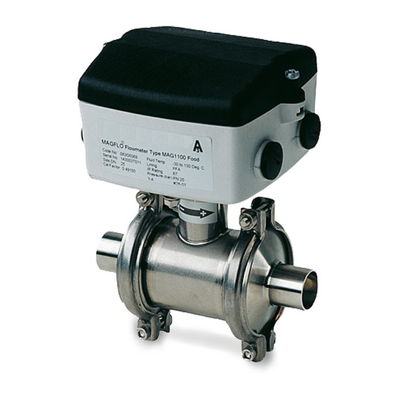
SITRANS F M MAGFLO MAG 1100 FOOD 2. Technical data 2.2 Sensor MAG 1100 FOOD MAG 1100 FOOD MAG 1100 FOOD PFA Type Hygienic sensor Nominal size DN 10, 15, 25, 40, 50, 65, 80, 100 Process connection Hygienic adapters available for: ♦... -
Page 10: Sensor Mag 3100, Mag 3100 Ex And Mag 3100 W
SITRANS F M MAGFLO 2. Technical data MAG 3100, MAG 3100 Ex and MAG 3100 W 2.3 Sensor MAG 3100, MAG 3100 Ex and MAG 3100 W MAG 3100 MAG 3100 Ex / Ex-d MAG 3100 W Type Sensor with flanges Sensor with flanges Sensor with flanges Nominal size... - Page 11 SITRANS F M MAGFLO 2. Technical data MAG 3100, MAG 3100 Ex and MAG 3100 W 2.3 Sensor MAG 3100, MAG 3100 Ex and MAG 3100 W (continued) MAG 3100 MAG 3100 Ex / Ex-d MAG 3100 W Flanges Standard DN 15-50: PN 40...
-
Page 12: Sensor Mag 5100 W
SITRANS F M MAGFLO 2. Technical data MAG 5100 W 2.4 Sensor MAG 5100 W Type Sensor with flanges Design Straight Coned 1 DN reduction Straight Nominal size 25-40 50-300 350-1200 Liner Hard elastomer Composite elastomer Hard elastomer (hard rubber) (hard &... -
Page 13: Signal Converter Mag 5000 (Dn 6 To Dn 1200)
SITRANS F M MAGFLO 2. Technical data MAG 5000 and MAG 5000 CT 2.5.1 Signal converter MAG 5000 (DN 6 to DN 1200) Accuracy 0.5% Current output Current 0-20 mA, 4-20 mA or 4-20 mA + alarm < 800 ohm Load Time constant 0.1-30 s adjustable... -
Page 14: Signal Converter Mag 6000
SITRANS F M MAGFLO 2. Technical data MAG 6000 and MAG 6000 CT 2.5.2 Signal converter MAG 6000 Accuracy 0.25% Current output Current 0-20 mA, 4-20 mA or 4-20 mA + alarm < 800 ohm Load Time constant 0.1-30 s adjustable Digital output Frequency 0-10 kHz, 50% duty cycle... -
Page 15: Safety Barrier (Ia/Ib) Dn ≤ 300
2. Technical data Safety barrier & cleaning unit 2.5.3 Application As combined unit with MAG 6000 only and MAG 1100 Ex/3100 Ex in the size Safety barrier (ia/ib) range DN 6-300 DN ≤ ≤ ≤ ≤ ≤ 300 Ex approval [EEx ia/ib] IIB Capacity in µF... -
Page 16: Meter Uncertainty
SITRANS F M MAGFLO 2. Technical data MAG 5000 or MAG 6000 used with MAG 3100 W or MAG 1100 PFA Meter uncertainty V: Actual flow velocity [m/s] E: Meter uncertainty as a percentage of actual flow MAG 6000 used with MAG 3100, MAG 1100 Ceramic or MAG 5100 W... -
Page 17: Output Characteristics Mag 5000 And Mag 6000
SITRANS F M MAGFLO 2. Technical data Output characteristics Bidirectional mode Unidirectional mode Output characteristics 0-20 mA MAG 5000 and MAG 6000 4-20 mA Frequency Pulse output Relay Power down Active Error relay No error Error Limit switch or 1 set point 2 set points direction switch... -
Page 18: Sensor Cables And Conductivity Of Medium
HART is a registered trademark of the HART Communication Foundation. 2.10 Standard cable Special cable Cable data (electrode/coil) (electrode) (Supplied by Siemens Basic data No. of conductors Flow Instruments) Sqr. area 1.5 mm 0.25 mm Screen Double Color code... -
Page 19: Project Guidance
3. Project guidance SITRANS F M MAGFLO 3. Project guidance Sizing table (DN 6 to DN 2000) The table shows the relationship between flow velocity V, flow quantity Q and sensor dimension Guidelines for selection of sensor Min. measuring range: 0-0.25 m/s Max. -
Page 20: Minimum Conductivity
3. Project guidance SITRANS F M MAGFLO 3.2.1 Applications Min. conductivity Minimum conductivity 5 µS/cm Compact mounted 5 µS/cm Remote mounted 20 µS/cm With empty pipe detection Ex-installations 30 µS/cm (Remote mounted only) District heating systems 250 µS/cm (Without DC cleaning unit) 3.2.2 Liner Applications... - Page 21 3. Project guidance SITRANS F M MAGFLO The sensor must always be completely full with Installation conditions liquid. (continued) Therefore avoid: • Installation at the highest point in the pipe system • Installation in vertical pipes with free outlet For partially filled pipes or pipes with downward flow and free outlet the flowmeter should be located in a U-tube.
- Page 22 C. Built-in earthing electrodes. (MAG 3100 and MAG 3100 W). D. Optional earthing/protection flanges/rings. (MAG 1100 and MAG 3100). E. Optional graphite gaskets on MAG 1100. (Standard for MAG 1100 High temperature). Vacuum Avoid a vacuum in the measuring pipe, since this can damage certain liners.
- Page 23 3. Project guidance SITRANS F M MAGFLO Compact/remote installa- The sensor and signal converter can be installed tion either compact or remote. With compact installation the temperature of medium must be according to the graph. With remote installation, the cable length and type described under "Technical data", chapter 2 must be used.
-
Page 24: Cleaning Unit
3. Project guidance SITRANS F M MAGFLO The Siemens Flow Instruments cleaning unit can be used with MAG 5000 or 6000 in 19" insert version. Cleaning unit The cleaning unit can be used in applications where the liner material and subsequently the electrodes may be coated with deposits. -
Page 25: Custody Transfer Approval
3. Project guidance SITRANS F M MAGFLO A signal converter can be supplied in a version tested and approved for custody transfer (CT ). Custody transfer ap- The internal counter can accordingly be used proval for charging. This requires verification, sealing and setting of the signal converter together with the sensor for a specific flow range. -
Page 26: Ex Installations
MAG 5000/6000 19” with safety barrier (ia/ib) for separate mounting in safe area Approval [EEx ia/ib] llB. The safety barrier is to be used with sensors MAG 1100 Ex and MAG 3100 Ex, DN 6 - 300. When this safety barrier is used, the coil circuit is intrinsic safety “ib” and the electrode circuit is intrinsic safety “ia”. -
Page 27: Dimensions And Weight
The total built-in length "L" [mm] before assembling depends on the gasket selected. EPDM Graphite PTFE(Teflon) Without gasket Earthing ring The MAG 1100 DN 6 and DN 10 are prepared for assembly with the 1/2" pipe connection. The length "L" varies dependent on the gasket choice: Without gasket EPDM... -
Page 28: Sensor Mag 1100 Food
SITRANS F M MAGFLO 4. Dimensions and weight MAG 1100 FOOD, compact and separate Sensor MAG 1100 FOOD Weight (PFA) [ [ [ [ [ mm] ] ] ] ] [ [ [ [ [ mm] ] ] ] ]... - Page 29 SITRANS F M MAGFLO 4. Dimensions and weight Accessories MAG 1100 FOOD Weld-in type Adapter Sensor ® DIN 11850 DS/ISO 2037 SMS 3008 BS4825-1 Tri-Clover [mm] [mm] [mm] [mm] [mm] [mm] [mm] [mm] [mm] [mm] [mm] [mm] [mm] 10.0 13.0...
- Page 30 SITRANS F M MAGFLO 4. Dimensions and weight Accessories MAG 1100 FOOD (continued) Threaded type Adapter Sensor DIN 11851 [mm] [mm] [mm] [mm] [mm] 10.0 28.0 16.0 34.0 20.0 44.0 26.0 52.0 32.0 58.0 38.0 65.0 50.0 78.0 66.0 95.0...
-
Page 31: Sensor Mag 5100 W
SITRANS F M MAGFLO 4. Dimensions and weight Sensor MAG 5100 W Dimensions Nominal PN 10 PN 16 PN 40 Class 150 AWWA size inch inch inch inch inch inch inch 1" 1½” 2" 2½” 3" 4" 5" 6" 11.8 11.8 8"... - Page 32 SITRANS F M MAGFLO 4. Dimensions and weight MAG 5100 W weight Nominal size PN 10 PN 16 PN 40 Class 150 AWWA inch 1" 1½” 2" 2½” 10.7 3" 11.6 4" 15.2 5" 20.4 6" 8" 10" 12" 14"...
-
Page 33: Sensor Mag 3100 And Mag 3100 W
SITRANS F M MAGFLO 4. Dimensions and weight MAG 3100 & MAG 3100 W, compact/separate Sensor MAG 3100 and MAG 3100 W BS 1560/ 2129 E, AWWA EN 1092-1-2001 ANSI 16.5 AS 4087 C-207 Class Class Class Class [mm] [mm] [mm] [mm]... -
Page 34: Signal Converter
SITRANS F M MAGFLO 4. Dimensions and weight Earthing/protection flange Weight Weight [mm] [kg] [mm] [mm] [kg] 0.07 25-250 0.03-0.4 25-150 0.3-1.4 300-600 0.6-2.6 200-350 1.7-4.1 700-1200 400-600 6.5-13.0 1400-2000 9-16 Type C flanges for liners of neoprene, EPDM, Linatex and ebonite. - Page 35 SITRANS F M MAGFLO 4. Dimensions and weight Wall mounting box 21 TE Weight excl. signal converter: 2.3 kg Wall mounting box 42 TE Weight excl. signal converter: 2.9 kg Panel front unit 21 TE Weight excl. signal converter: 1.2 kg DKFD.PS.027.W3.02...
- Page 36 SITRANS F M MAGFLO 4. Dimensions and weight Panel front unit 42 TE Weight excl. signal converter: 1.6 kg Back of panel unit 21 TE Weight: 0.7 kg Back of panel unit 42 TE Weight: 0.9 kg DKFD.PS.027.W3.02...
-
Page 37: Installation Of Sensor
C: Potential equalization with electri- D: Potential equalization using sepa- cally conductive graphite gaskets rate potential equalization ring MAG 1100 FOOD The sensor must be installed between two adap- ters. Potential equalization with the liquid oc- curs automatically via these adapters and through the adjacent pipe. -
Page 38: Inlet Protection Mag 3100
SITRANS F M MAGFLO 5. Installation of sensor MAG 3100 Electrically conductive piping (PTFE liner) Use an earth straps on one side. Potential equalization, electrically conductive pipe Non-conductive piping Use an earthing flange. Place the flange between flowmeter and the adjacent pipe flange. Selection of earthing flange depends on the medium, liner material and application, see figure. -
Page 39: Installation Of Signal Converter
SITRANS F M MAGFLO 6. Installation of signal converter Step 1 6. Installation of signal Remove and discard the terminal box lid of the converter sensor. Fit the PG 13.5 cable glands for the supply and Compact installation output cables. MAG 5000 and MAG 6000 Compact polyamide Step 2... - Page 40 SITRANS F M MAGFLO 6. Installation of signal converter 1. Use a screw driver to remove the outer Turning the control pad frame. 2. Loosen the 4 screws retaining the control pad. 3. Withdraw the control pad and turn it to the required orientation.
-
Page 41: Add-On Modules Mag 6000 Only
SITRANS F M MAGFLO 6. Installation of signal converter 6.2.1 Locate the add-on module in the bottom of the Add-on modules MAG 6000 signal converter. MAG 6000 only Press the add-on module forwards as far as possible. The add-on module has now been installed and the signal converter is ready to be installed on the terminal box. -
Page 42: Remote Installation. Wall Mounting
SITRANS F M MAGFLO 6. Installation of signal converter 6.2.3 Mount wall bracket on a wall or into the back of Remote installation - a panel. Wall mounting MAG 6000 Vertical pipe mounting Mount wall bracket on a vertical or horizontal pipe using an ordinary hose clip or a duct strap. - Page 43 SITRANS F M MAGFLO 6. Installation of signal converter 6.2.3 Mount the connection plate in the terminal box. Remote installation - Fix the connection plate with the two diagonal opposite screws. Wall mounting (continued) Fit the coil, electrode, supply and output cables respectively and tighten the cable glands to obtain optimum sealing.
-
Page 44: Remote Installation. Signal Converter In 19" Insert
SITRANS F M MAGFLO 6. Installation of signal converter 6.2.4 Remote installation - Signal converter in 19" insert ® 1. Fit the SENSORPROM memory unit on the connection board supplied with the signal ® converter. The SENSORPROM unit is supplied with the sensor in the terminal box. 2. -
Page 45: Add-On Modules Mag 6000 Only
SITRANS F M MAGFLO 6. Installation of signal converter 6.2.5 Locate the add-on module in the bottom of the Add-on modules MAG 6000 signal converter. MAG 6000 only Press the add-on module forwards as far as possible. The add-on module has now been installed and the signal converter is ready to be installed on the terminal box. -
Page 46: Installation In Ip 65 Wall Mounting Enclosure
SITRANS F M MAGFLO 6. Installation of signal converter 6.2.6 Installation in IP 65 wall mounting enclosure 1. Mount the IP 65 enclosure on the wall with four screws. ® 2. Mount the SENSORPROM memory unit on the connection board as shown. ®... -
Page 47: Installation In Ip 65 Panel Mounting Enclosure (Front Of Panel)
SITRANS F M MAGFLO 6. Installation of signal converter 6.2.7 Installation in IP 65 panel mounting enclosure (front of panel) 1. Mount the SENSORPROM ® memory unit on the connection board as shown. The SENSORPROM ® unit is supplied with the sensor in the terminal box. 2. -
Page 48: Installation Into The Back Of A Panel
SITRANS F M MAGFLO 6. Installation of signal converter 6.2.8 Installation into the back of a panel 1. Mount the SENSORPROM ® memory unit on the connection board as shown. The SENSORPROM ® unit is supplied with the sensor in the terminal box. 2. -
Page 49: Signal Converter Safety Barrier
SITRANS F M MAGFLO 6. Installation of signal converter Signal converter Safety barrier 1. Fit the SENSORPROM ® memory unit on the connection board supplied with the safety barrier. The SENSORPROM ® unit is delivered mounted in the terminal box of the sensor. The connection board supplied with the signal converter is not used. -
Page 50: Signal Converter Cleaning Unit
SITRANS F M MAGFLO 6. Installation of signal converter Signal converter Cleaning unit 1. Fit the SENSORPROM ® memory unit on the connection board supplied with the cleaning unit. The SENSORPROM ® unit is delivered mounted in the terminal box of the sensor. The connection board supplied with the signal converter is not used. -
Page 51: Electrical Connection
SITRANS F M MAGFLO 7. Electrical connection 7. Electrical connection Signal converter MAG 5000 and MAG 6000 connection diagram Note Special cable with individual wire shields (shown as dotted lines) are only requried when using empty pipe function or long cables. (See “Technical data”... -
Page 52: Wiring Diagram For Signal Converter And Sensor
7. Electrical connection SITRANS F M MAGFLO Compact Wiring diagram for signal converter and sensor Compact installation Note Mount the grounding wire from connection box to PE to ensure sufficient grounding. Cathodic protected piping Compact installation: The signal converter must be supplied through an isolation transformer. The terminal "PE" must not be connected. - Page 53 SITRANS F M MAGFLO 7. Electrical connection 19” IP 20 version 19” IP 66 version 19” IP 20 version EEx (ia/ib) DN ≤ ≤ ≤ ≤ ≤ 300 DKFD.PS.027.W3.02...
- Page 54 7. Electrical connection SITRANS F M MAGFLO 19” IP 20 version EEx e (ib) DN ≥ ≥ ≥ ≥ ≥ 350 19” IP 66 version EEx (ia/ib) DN ≤ ≤ ≤ ≤ ≤ 300 19” IP 66 version EEx e (ib) DN ≥ ≥ ≥ ≥ ≥ 350 DKFD.PS.027.W3.02...
- Page 55 SITRANS F M MAGFLO 7. Electrical connection 19” IP 20 version with cleaning 19” IP 66 version with cleaning DKFD.PS.027.W3.02...
-
Page 56: Commissioning
SITRANS F M MAGFLO 8. Commissioning 8. Commissioning Keypad and display layout Keypad The keypad is used to set the flowmeter. The function of the keys is as follows: TOP UP KEY This key (hold 2 sec.) is used to switch between operator menu and setup menu. -
Page 57: Menu Build-Up
8. Commissioning SITRANS F M MAGFLO The menu structure of a specific signal converter type is shown in a menu overview map. Details of how a specific parameter is set is shown in a menu detail map for the specific parameter. Menu build-up A detail map is valid for each type of signal converter if not indicated otherwise. -
Page 58: Mag 5000 And Mag 6000
SITRANS F M MAGFLO 8. Commissioning Menu overview 8.3.1 MAG 5000 and MAG 6000 DKFD.PS.027.W3.02... -
Page 59: Mag 6000 Ct
8. Commissioning SITRANS F M MAGFLO Menu overview 8.3.2 MAG 6000 CT DKFD.PS.027.W3.02... -
Page 60: Basic Settings
SITRANS F M MAGFLO 8. Commissioning Menu detail 8.4.1 Main frequency Basic settings To select the main power supply frequency corresponding to the country in which the flowmeter is installed. (US = 60 Hz) Flow direction Select the correct flow direction in the pipe max. -
Page 61: Outputs
8. Commissioning SITRANS F M MAGFLO Menu detail 8.4.2 Outputs Current output Proportional to flowrate (Terminal 31 and 32) 4 - 20 mA + alarm: Current output gives the following mA, depending on what is selected as error level in basic settings. Fatal: 1 mA, permanent: 2 mA, warning: 3 mA The current output must be set off when not used. -
Page 62: Relay Outputs
SITRANS F M MAGFLO 8. Commissioning Menu detail Limit/direction Limit switches are available for both digital as well as relay output. Direction mode: 1 set point at 0% flow; hysteresis 5%. If 2 set points must activate 2 separate outputs, a single set point has to be selected individually for digital as well as relay outputs. -
Page 63: Sensor Characteristics
8. Commissioning SITRANS F M MAGFLO Menu detail 8.4.6 Sensor characteristics If “SENSORPROM not installed” is shown, refer to chapter 6 (depending on type of mounting configura- tion). 8.4.7 Reset mode DKFD.PS.027.W3.02... -
Page 64: Service Mode
SITRANS F M MAGFLO 8. Commissioning Menu detail 8.4.8 Service mode 1) Standard 2) If digital output is set to frequency All previous settings are reinitialised when service mode is exited using the top up key. The error system The error system is divided into an error pending list and a status log list. -
Page 65: Operator Menu Setup
8. Commissioning SITRANS F M MAGFLO Menu setup 8.4.9 Operator menu setup Text means that the text for the chosen measured value is shown. For example if text is chosen in line 2 and flow rate is chosen in line 3, the text “flow rate”... -
Page 66: Product Identity
SITRANS F M MAGFLO 8. Commissioning Menu detail 8.4.10 Product identity Software version of add-on module is only available if the add-on module has been installed. 8.4.11 Change password DKFD.PS.027.W3.02... -
Page 67: Language Mode
8. Commissioning SITRANS F M MAGFLO Menu detail 8.4.12 Language mode 8.4.13 HART communication MAG 5000 HART or as add-on module DKFD.PS.027.W3.02... -
Page 68: Flow Rate
SITRANS F M MAGFLO 8. Commissioning Operator menu 8.5.1 Flow rate The 1 display line is always active and shows the value enabled in the operator menu setup. • Flow rate • Totalizer 1 • Totalizer 2 The 2 and 3 display lines are individually set in the operator menu. -
Page 69: Settings Available
8. Commissioning SITRANS F M MAGFLO 8.6.1 The signal converter is delivered with factory settings ready to measure the actual flow. Settings available Parameter Factory settings Settings available Password Default value 1000 Password 1000 1000 - 9999 Basic settings Flow direction Positive Positive, negative... -
Page 70: Dimension Dependent Factory Settings Mag 5000 And Mag 6000
SITRANS F M MAGFLO 8. Commissioning 8.6.2 max. Dimension dependent MAG 5100 W MAG 1100, factory settings 3100, 3100 W Volume/ Pulse Totalizer MAG 5000 and MAG 6000 [inches] fac.set. min. max. min. max. unit pulse unit unit 25.5 1017 70.7... -
Page 71: Mag 5000 Ct And Mag 6000 Ct Settings
8. Commissioning SITRANS F M MAGFLO 8.6.4 Setting primary operating parameters such as Q , low flow cut-off, units, approvals, etc. is blocked max. MAG 5000 CT and during normal operation. See menu setup. MAG 6000 CT settings These settings are made in connection with commissioning or calibration by mounting a hardware key on the connection plate of the signal converter. -
Page 72: Error Handling
SITRANS F M MAGFLO 8. Commissioning 8.7.1 Error system Error handling The converter system is equipped with an error and status log system with 4 groups of information. • Information without a functional error involved • Warnings which may cause malfunction in the application. The cause of the error may disappear on its own •... -
Page 73: List Of Error Numbers
8. Commissioning SITRANS F M MAGFLO 8.7.2 Error Error text #Comment Outputs Input List of error numbers Remedy text status status I1 - Power on Power on has happened Active Active I2 - Add-on module Applied A new module has been applied to the system Active Active I3 - Add-on module... -
Page 74: Service
SITRANS F M MAGFLO 9. Service 9. Service Often problems with unstable/wrong measurements occur due to insufficient/wrong earthing or potential equalization. Please check this connection. If OK, the SITRANS F M MAGFLO con- verter can be checked as described under 9.1 and sensor under 9.3. ... -
Page 75: Trouble Shooting Mag Converter
SITRANS F M MAGFLO 9. Service Symptom Output Error Cause Remedy Trouble shooting signals code MAG converter Empty display Minimum 1. No power supply Power supply Check MAG 5000/6000 for bended pins on the connector 2. MAG 5000/6000 defective Replace MAG 5000/6000 No flow signal Minimum... -
Page 76: Check List Mag Sensor
9. Service ATTENTION! Check list MAG sensor If there is leakage from MAG 1100/3100/3100 W or MAG 5100 W and the unit has been used to measure inflammable/explosive liquids, there might be a risk of explosion when checking with a megger. -
Page 77: Coil Resistance Table
Coil resistance for MAG 1100, MAG 1100 PFA = 98 ohms +/− Coil resistance Note On MAG 1100 DN 15 produced as from May 1999 the coil resistance must be 86 ohm, +8/−4 ohm. Coil resistance MAG 3100 MAG 3100 W... -
Page 78: Ordering
FDK:083G5051 2 EPDM gaskets, studs and nuts DN 50 FDK:083G5052 DN 65 FDK:083G5053 DN 80 FDK:083G5054 DN 100 FDK:083G5055 MAG 1100 (High temperature) DN 15 FDK:083G4057 Ceramic Al DN 25 FDK:083G4059 Temperature of medium max. 200°C DN 40 FDK:083G4061 Included:... - Page 79 6, 10 FDK:083G0116 2 gaskets FDK:083G0117 FDK:083G0119 FDK:083G0121 FDK:083G0122 FDK:083G0123 FDK:083G0124 FDK:083G0125 Gaskets for Description Material Code No. Symbol MAG 1100 FOOD EPDM gaskets EPDM FDK:083G2206 2 gaskets FDK:083G2207 FDK:083G2209 FDK:083G2211 FDK:083G2212 FDK:083G2213 FDK:083G2214 FDK:083G2215 NBR gaskets FDK:083G2216 2 gaskets...
-
Page 80: Adapter, Mag 1100 Food (Contains 2 Adapters, 2 Clamp Rings And 2 Gaskets)
SITRANS F M MAGFLO 10. Ordering 10.2 Adapter, MAG 1100 FOOD (contains 2 adapters, 2 clamp rings and 2 gaskets) Adapter Sensor Weld-in type: Matching standard DIN 11850 DS/ISO 2037 SMS 3008 BS 4825-1 Tri-Clover Symbol [mm] [mm] [mm] [mm] Code No. - Page 81 SITRANS F M MAGFLO 10. Ordering 10.2 Threaded type: Matching standard Adapter, MAG 1100 FOOD Adapter Sensor DIN 11851 Symbol (continued) [mm] [mm] [mm] [mm] Code No. 28.0 10.0 FDK:083G2156 34.0 16.0 FDK:083G2157 44.0 20.0 FDK:083G2158 52.0 26.0 FDK:083G2159 58.0...
-
Page 82: Sensor Mag 3100 And Mag 3100 Ex
SITRANS F M MAGFLO 10. Ordering MAG 3100 − − − − − 10.3 Type No.: Sensor MAG 3100 and MAG 3100 Ex 1. Nominal size DN 15 ................. 25 ................. 40 ................. 50 ................. 65 ................. 80 ................. 100 ................. - Page 83 SITRANS F M MAGFLO 10. Ordering Earthing/protection flange Flange EN 1092-1 ANSI B 16.5 type C (AISI 304) for all PN 6 PN 10 PN 16 PN 25 PN 40 150 lb 300 lb Pressure liners except PTFE for FDK: FDK: FDK:...
-
Page 84: Sensor Mag 3100 W
SITRANS F M MAGFLO 10. Ordering 10.4 Code No. Sensor MAG 3100 W EN 1092-1 flanges Neoprene EPDM liner liner Liner: Neoprene or EPDM FDK:083Z8000 FDK:083Z8100 Flanges: Carbon steel, EN 1092-1 FDK:083Z8001 FDK:083Z8101 Electrodes: AISI 316 Ti FDK:083Z8002 FDK:083Z8102 Grounding electrodes: AISI 316 Ti FDK:083Z8003 FDK:083Z8103... -
Page 85: Sensor Mag 5100 W
SITRANS F M MAGFLO 10. Ordering 10.5 EN 1092-1 flanges Code No. Sensor MAG 5100 W Liner: Composite elastomer or FDK:082Z8500 hard elastomer FDK:082Z8502 Flanges: Carbon steel, EN 1092-1 40*) FDK:082Z8504 Electrodes: AISI 316 Ti FDK:082Z8506 Grounding electrodes: AISI 316 Ti FDK:082Z8508 Enclosure: IP 67 FDK:082Z8510... -
Page 86: Signal Converter
SITRANS F M MAGFLO 10. Ordering 10.6 Description Version Enclosure Code No. Symbol Signal converter Signal converter MAG 5000 Blind 11-30 V d.c./ IP 67, fibre- for compact and wall mounting 11-24 V a.c. glass reinforced FDK:083F5006 Compact polyamide polyamide 115/230 V a.c. -
Page 87: Signal Converter 19" Incl. Back Plate
SITRANS F M MAGFLO 10. Ordering 10.7 Description Version Code No. Symbol Signal converter 19" incl. Signal converter MAG 5000 for rack 11-30 V d.c./ FDK:083F5021 back plate and panel mounting 11-24 V a.c. 115-230 V a.c. FDK:083F5020 50/60 Hz Signal converter MAG 6000 for rack 11-30 V d.c./ FDK:083F5023... -
Page 88: Accessories
SITRANS F M MAGFLO 10. Ordering Back plates Description Enclosure Version Code No. Symbol Signal converter 19" 12-24 V FDK:083F4117 115-230 V Signal converter & ia, safety barrier 19" 12-24 V FDK:083F4118 115-230 V Signal converter & ia/ib, safety barrier 19"... -
Page 89: Calibration
Customer specified matched pair Sensor with signal converter calibrated in max. 10 customer specified points Code No.: On application form to be filled Accredited Siemens Flow Instruments in and sent to SFI-GB matched pairs Calibrations acc. to EN 45001 Sealing and labeling instruction must follow... - Page 90 SITRANS F M MAGFLO DKFD.PS.027.W3.02...
- Page 91 SITRANS F M MAGFLO DKFD.PS.027.W3.02...
- Page 92 Suggestions for improvement registration of a utility model or design, are reserved. are always welcomed. Technical data subject to change without prior notice. Copyright © Siemens AG 2002 All Rights Reserved SIEMENS Order no.: FDK:521H0723-01 Flow Instruments A/S...
Need help?
Do you have a question about the MAG 1100 and is the answer not in the manual?
Questions and answers