Vega VEGABAR 83 Operating Instructions Manual
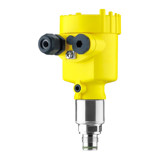
Pressure transmitter with metallic measuring cell
Hide thumbs
Also See for VEGABAR 83:
- Operating instructions manual (108 pages) ,
- Quick setup manual (24 pages) ,
- Product information (16 pages)

Related Manuals for Vega VEGABAR 83


Summary of Contents for Vega VEGABAR 83
- Page 1 Operating Instructions Pressure transmitter with metallic measuring cell VEGABAR 83 4 … 20 mA/HART Document ID: 45034...
-
Page 2: Table Of Contents
Adjustment system ......................34 Measured value indication ....................35 Parameter adjustment - Quick setup ................36 Parameter adjustment - Extended adjustment..............36 Menu overview ....................... 48 Save parameter adjustment data..................50 Setup with PACTware ......................52 VEGABAR 83 • 4 … 20 mA/HART... - Page 3 11.5 Industrial property rights ....................94 11.6 Trademark ........................94 Safety instructions for Ex areas: Take note of the Ex specific safety instructions for Ex applications. These instructions are attached as documents to each instrument with Ex approval and are part of the operating instructions. Editing status: 2022-04-20 VEGABAR 83 • 4 … 20 mA/HART...
-
Page 4: About This Document
Symbols used Document ID This symbol on the front page of this instruction refers to the Docu- ment ID. By entering the Document ID on www.vega.com you will reach the document download. Information, note, tip: This symbol indicates helpful additional infor- mation and tips for successful work. -
Page 5: For Your Safety
During work on and with the device, the required personal protective equipment must always be worn. Appropriate use The VEGABAR 83 is a pressure transmitter for process pressure and hydrostatic level measurement. You can find detailed information about the area of application in chapter " Product description". Operational reliability is ensured only if the instrument is properly used according to the specifications in the operating instructions manual as well as possible supplementary instructions. -
Page 6: Namur Recommendations
• Chapter " Packaging, transport and storage" • Chapter " Disposal" Exception: Versions with measuring ranges from 250 bar. These are subject of the EU Pressure Device Directive. Not fulfilled when connecting to an external display and adjustment unit. VEGABAR 83 • 4 … 20 mA/HART... -
Page 7: Product Description
Hardware from 1.0.0 • Software from 1.3.6 Note: You can find the hardware and software version of the instrument as follows: • On the type plate of the electronics module • In the adjustment menu under " Info" Type label The type label contains the most important data for identification and use of the instrument: VEGABAR 83 • 4 … 20 mA/HART... -
Page 8: Principle Of Operation
Alternatively, you can access the data via your smartphone: • Download the VEGA Tools app from the " Apple App Store" or the " Google Play Store" • Scan the QR-code on the type label of the device or •... - Page 9 3 Product description Fig. 2: Process pressure measurement VEGABAR 83 Electronic differential Depending on the version, the VEGABAR 83 is also suitable for pressure electronic differential pressure measurement. For this, the instrument is combined with a Secondary sensor. Fig. 3: Electronic differential pressure measurement via a Primary/Secondary sensor combination You can find detailed information in the operating instructions of the respective Secondary sensor.
- Page 10 With small measuring ranges or higher temperatures, the ceramic/ metallic METEC measuring cell is the measuring unit. It consists ® of the ceramic-capacitive CERTEC measuring cell and a special, ® temperature-compensated chemical seal system. VEGABAR 83 • 4 … 20 mA/HART...
- Page 11 Seal concept The measuring system is completely welded and thus sealed against the process. The process fitting is sealed against the process by a suitable seal. It must be provided by the customer, depending on the process fitting also included in the scope of delivery, see chapter " Technical data", " Materials and weights". VEGABAR 83 • 4 … 20 mA/HART...
-
Page 12: Supplementary Cleaning Procedures
3 Product description Supplementary cleaning procedures The VEGABAR 83 is also available in the version " Oil, grease and silicone-free". These instruments have passed through a special cleaning procedure to remove oil, grease and paint-wetting impair- ment substances (PWIS). The cleaning is carried out on all wetted parts as well as on surfaces accessible from outside. -
Page 13: Accessories
USB interface of a PC. Secondary sensors Secondary sensors of VEGABAR series 80 enable in conjunction with VEGABAR 83 an electronic differential pressure measurement. VEGADIS 81 The VEGADIS 81 is an external display and adjustment unit for VEGA plics sensors. ® VEGADIS adapter The VEGADIS adapter is an accessory part for sensors with double chamber housings. -
Page 14: Mounting
Depending on the device version, tightening can cause dam- age, e. g. to the rotation mechanism of the housing. Vibrations Avoid damages on the device by lateral forces, for example by vibra- tions. It is thus recommended to fix the devices with process fitting VEGABAR 83 • 4 … 20 mA/HART... -
Page 15: Instructions For Oxygen Applications
Process temperature Ambient temperature Instructions for oxygen applications Oxygen applications Oxygen and other gases can be explosive when brought into contact with oils, grease and plastics, so the following measures must also be taken: VEGABAR 83 • 4 … 20 mA/HART... -
Page 16: Ventilation And Pressure Compensation
5 s by up to 15 mbar. For an effective ventilation, the filter element must be always free from buildup. In case of horizontal mounting, turn the housing so that the filter element points downward after the instrument is installed. This provides better protection against buildup. Caution: Do not use a high-pressure cleaner. The filter element could be dam- aged, which would allow moisture into the housing. The following paragraphs describe how the filter element is arranged in the different instrument versions. VEGABAR 83 • 4 … 20 mA/HART... - Page 17 This provides better protection against buildup. Fig. 9: Position of the filter element - Ex-d version Rotatable metal ring Filter element Instruments with absolute pressure have a blind plug mounted instead of the filter element. VEGABAR 83 • 4 … 20 mA/HART...
-
Page 18: Process Pressure Measurement
Instruments with absolute pressure have a blind plug mounted instead of the filter element. Process pressure measurement Measurement setup in Keep the following in mind when setting up the measuring system: gases • Mount the instrument above the measuring point Possible condensation can then drain off into the process line. VEGABAR 83 • 4 … 20 mA/HART... - Page 19 Siphon in U or circular form Pipeline A protective accumulation of water is formed through condensation in the pipe bends. Even in applications with hot steam, a medium temperature < 100 °C on the transmitter is ensured. VEGABAR 83 • 4 … 20 mA/HART...
-
Page 20: Level Measurement
Mount the instrument below the min. level • Do not mount the instrument close to the filling stream or emptying area • Mount the instrument so that it is protected against pressure shocks from the stirrer Fig. 15: Measurement setup for the level measurement VEGABAR 83 • 4 … 20 mA/HART... -
Page 21: External Housing
4 Mounting External housing Configuration Fig. 16: Configuration, process module, external housing Pipeline Process module Connection cable process assembly - External housing External housing Signal cable VEGABAR 83 • 4 … 20 mA/HART... -
Page 22: Connecting To Power Supply
The ground terminal on the outside of the housing must be connected to the ground potential (low impedance). In Ex systems, the grounding is carried out according to the installa- tion regulations. In electroplating plants as well as plants for cathodic corrosion protec- tion it must be taken into account that significant potential differences VEGABAR 83 • 4 … 20 mA/HART... -
Page 23: Connecting
1. Unscrew the housing lid 2. If a display and adjustment module is installed, remove it by turn- ing it slightly to the left 3. Loosen compression nut of the cable gland and remove blind plug VEGABAR 83 • 4 … 20 mA/HART... -
Page 24: Single Chamber Housing
10. Reinsert the display and adjustment module, if one was installed 11. Screw the housing lid back on The electrical connection is finished. Single chamber housing The following illustration applies to the non-Ex, Ex-ia and Ex-d ver- sion. VEGABAR 83 • 4 … 20 mA/HART... -
Page 25: Double Chamber Housing
The following illustrations apply to the non-Ex as well as to the Ex-ia version. Electronics compartment 4...20mA 6 7 8 Fig. 19: Electronics compartment - double chamber housing Internal connection to the connection compartment For display and adjustment module or interface adapter VEGABAR 83 • 4 … 20 mA/HART... - Page 26 " Additional current output" First current output (I) - Voltage supply and signal output, sensor (HART) Additional current output (II) - Voltage supply and signal output (without HART) Ground terminal for connection of the cable screening VEGABAR 83 • 4 … 20 mA/HART...
-
Page 27: Ex-D-Ia Double Chamber Housing
For display and adjustment module or interface adapter Internal connection to the plug connector for external display and adjust- ment unit (optional) Note: HART multidrop mode is not possible when using an Ex-d-ia instru- ment. VEGABAR 83 • 4 … 20 mA/HART... -
Page 28: Double Chamber Housing With Vegadis-Adapter
VEGADIS adapter Internal plug connection M12 x 1 plug connector Assignment of the plug connector Fig. 26: Top view of the M12 x 1 plug connector Pin 1 Pin 2 Pin 3 Pin 4 VEGABAR 83 • 4 … 20 mA/HART... -
Page 29: Housing Ip66/Ip68 (1 Bar)
Blue (-): to voltage supply or to the processing system Shielding Breather capillaries with filter element External housing with version IP68 (25 bar) Overview Fig. 28: VEGABAR 83 in IP68 version 25 bar with axial cable outlet, external housing Transmitter Connection cable External housing... - Page 30 Cable gland for voltage supply Cable gland for connection cable, transmitter Terminal compartment, housing socket 1 2 3 4 Fig. 30: Connection of the process component in the housing base Yellow White Black Shielding Breather capillaries VEGABAR 83 • 4 … 20 mA/HART...
-
Page 31: Connection Example
Ground terminal for connection of the cable screening Connection example Connection example, ad- ditional current output 4...20mA 4...20mA Fig. 32: Connection example VEGABAR 83 additional current output Supply and signal circuit, sensor Signal circuit, additional current output Input card PLC Sensor Circuit... -
Page 32: Switch-On Phase
The output signal jumps to the set fault current Then the actual measured value is output to the signal cable. The value takes into account settings that have already been carried out, e.g. default setting. VEGABAR 83 • 4 … 20 mA/HART... -
Page 33: Set Up With The Display And Adjustment Module
The display and adjustment module is powered by the sensor, an ad- ditional connection is not necessary. Fig. 33: Installing the display and adjustment module in the electronics compart- ment of the single chamber housing VEGABAR 83 • 4 … 20 mA/HART... -
Page 34: Adjustment System
– Move to the menu overview – Confirm selected menu – Edit parameter – Save value • [->] key: – Change measured value presentation – Select list entry – Select menu items – Select editing position • [+] key: VEGABAR 83 • 4 … 20 mA/HART... -
Page 35: Measured Value Indication
[OK] will not be saved. Measured value indication Measured value indica- With the [->] key you can move between three different indication tion modes. In the first view, the selected measured value is displayed in large digits. In the second view, the selected measured value and a respective bargraph presentation are displayed. VEGABAR 83 • 4 … 20 mA/HART... -
Page 36: Parameter Adjustment - Quick Setup
[->] or [ESC] keys or automatically after 3 s Note: You can find a description of the individual steps in the quick setup guide of the sensor. You can find " Extended adjustment" in the next sub-chapter. Parameter adjustment - Extended adjustment For technically demanding measuring points, you can carry out extended settings in " Extended adjustment". VEGABAR 83 • 4 … 20 mA/HART... - Page 37 In this menu item you activate/deactivate the Secondary Device for electronic differential pressure and select the application. VEGABAR 83 can be used for process pressure and level measure- ment. The setting in the delivery status is process pressure measure- ment. The mode can be changed in this adjustment menu.
- Page 38 With relative pressure measuring cells a manual offset can also be carried out. Note: If the current measured value is automatically accepted, it must not be falsified by medium coverage or static pressure. With the manual position correction, the offset value can be deter- mined by the user. Select for this purpose the function " Edit" and enter the requested value. VEGABAR 83 • 4 … 20 mA/HART...
- Page 39 Adjustment VEGABAR 83 always measures pressure independently of the pro- cess variable selected in the menu item " Application". To output the selected process variable correctly, an allocation of the output signal to 0 % and 100 % must be carried out (adjustment).
- Page 40 If the adjustment ranges are exceeded, the message " Outside parameter limits" appears. The editing procedure can be aborted with [ESC] or the displayed limit value can be accepted with [OK]. The span adjustment is finished. VEGABAR 83 • 4 … 20 mA/HART...
- Page 41 5. Save settings with [OK] The max. adjustment is finished. For an adjustment with filling, simply enter the actual measured value indicated at the bottom of the display. Damping To damp process-dependent measured value fluctuations, set an integration time of 0 … 999 s in this menu item. The increment is 0.1 s. The set damping is effective for level and process pressure measure- ment as well as for all applications of electronic differential pressure measurement. VEGABAR 83 • 4 … 20 mA/HART...
- Page 42 In the menu item " Current output Min./Max.", you determine the reac- max.) tion of the current output during operation. The device assumes an approximately constant temperature and static pressure and converts the differential pressure into the flow rate via the characteristic curve extracted by root. VEGABAR 83 • 4 … 20 mA/HART...
- Page 43 Russian • Italian • Dutch • Portuguese • Japanese • Chinese • Polish • Czech • Turkish In delivery status, the VEGABAR 83 is set to English. Display value 1 and 2 In this menu item, you define which measured value is displayed. VEGABAR 83 • 4 … 20 mA/HART...
- Page 44 Peak value, temperature The respective min. and max. measured values of the measuring cell and the electronics temperature are stored in the sensor. In menu item " Peak value, temperature", both values are displayed. VEGABAR 83 • 4 … 20 mA/HART...
- Page 45 (daylight saving) time. Reset After a reset, certain parameter adjustments made by the user are reset. The following reset functions are available: Delivery status: Restores the parameter settings at the time of shipment from the factory, incl. the order-specific settings. Any user- VEGABAR 83 • 4 … 20 mA/HART...
- Page 46 In this menu item you gain access to the protected area where you can enter special parameters. In exceptional cases, individual parameters can be modified in order to adapt the sensor to special requirements. Change the settings of the special parameters only after having con- tacted our service staff. VEGABAR 83 • 4 … 20 mA/HART...
- Page 47 Multidrop mode. In the mode " Fixed current output" up to 63 sensors can be operated on one two-wire cable (Multidrop operation). An address between 0 and 63 must be assigned to each sensor. VEGABAR 83 • 4 … 20 mA/HART...
-
Page 48: Menu Overview
In this menu item, the features of the sensor such as approval, pro- Sensor characteristics cess fitting, seal, measuring range, electronics, housing and others are displayed. Menu overview The following tables show the adjustment menu of the instrument. Depending on the instrument version or application, all menu items may not be available or some may be differently assigned. VEGABAR 83 • 4 … 20 mA/HART... - Page 49 Ceramic measuring cell: Measuring cell temperature in °C Metallic measuring cell: Electronics temperature in °C Display format Number of positions after the decimal point, automatically Backlight Switched on Parameter only active if the instrument is connected to the Secondary Device VEGABAR 83 • 4 … 20 mA/HART...
-
Page 50: Save Parameter Adjustment Data
In the display and adjust- If the instrument is equipped with a display and adjustment module, ment module the parameter adjustment data can be saved therein. The procedure is described in menu item " Copy device settings". VEGABAR 83 • 4 … 20 mA/HART... - Page 51 6 Set up with the display and adjustment module VEGABAR 83 • 4 … 20 mA/HART...
-
Page 52: Setup With Pactware
Note: With power supply units with integrated HART resistance (internal resistance approx. 250 Ω), an additional external resistance is not necessary. This applies, e.g. to the VEGA instruments VEGATRENN 149A, VEGAMET 381, VEGAMET 391. Common Ex separators are also usually equipped with a sufficient current limiting resistance. In such cases, the interface adapter can be connected parallel to the 4 …... - Page 53 The standard version is available as a download under www.vega.com/downloads and " Software". The full version is avail- able on CD from the agency serving you. VEGABAR 83 • 4 … 20 mA/HART...
-
Page 54: Save Parameter Adjustment Data
7 Setup with PACTware Save parameter adjustment data We recommend documenting or saving the parameterisation data via PACTware. That way the data are available for multiple use or service purposes. VEGABAR 83 • 4 … 20 mA/HART... -
Page 55: Set Up With Other Systems
They can then be transferred to a Field Communicator. In the HART communication, the Universal Commands and a part of the Common Practice Commands are supported. VEGABAR 83 • 4 … 20 mA/HART... -
Page 56: Diagnosis, Asset Management And Service
Event memory Up to 500 events are automatically stored with a time stamp in the sensor (non-deletable). Each entry contains date/time, event type, event description and value. Event types are for example: VEGABAR 83 • 4 … 20 mA/HART... -
Page 57: Asset Management Function
The instrument is being worked on, the measured value is temporarily invalid (for example during simulation). This status message is inactive by default. Out of specification: The measured value is unreliable because an instrument specification was exceeded (e.g. electronics temperature). This status message is inactive by default. Maintenance required: Due to external influences, the instrument function is limited. The measurement is affected, but the measured value is still valid. Plan in VEGABAR 83 • 4 … 20 mA/HART... - Page 58 Send instrument for repair Error in the EEPROM F261 Error during setup Repeat setup Byte 4, Bit 1 of Byte 0 … 5 Error in the instrument Error when carrying out a reset Repeat reset settings VEGABAR 83 • 4 … 20 mA/HART...
- Page 59 M501 Index markers are not continu- Check linearization table Bit 1 of ously rising, for example illogical Byte 14 … 24 Error in the non-active Delete table/Create new value pairs linearisation table VEGABAR 83 • 4 … 20 mA/HART...
-
Page 60: Rectify Faults
24 hour service hotline Should these measures not be successful, please call in urgent cases the VEGA service hotline under the phone no. +49 1805 858550. The hotline is also available outside normal working hours, seven days a week around the clock. -
Page 61: Exchange Process Module On Version Ip68 (25 Bar)
Proceed as follows when carrying out the exchange: 1. Losen the fixing screw with the hexagon key wrench 2. Carefully detach the cable assembly from the process module Fig. 42: VEGABAR 83 in IP68 version, 25 bar and lateral cable outlet, external housing Process module Plug connector... -
Page 62: Exchanging The Electronics Module
• Attach the completed form and, if need be, also a safety data sheet outside on the packaging • Ask the agency serving you to get the address for the return ship- ment. You can find the agency on our homepage. VEGABAR 83 • 4 … 20 mA/HART... -
Page 63: Dismount
If personal data is stored on the old device to be disposed of, delete it before disposal. If you have no way to dispose of the old instrument properly, please contact us concerning return and disposal. VEGABAR 83 • 4 … 20 mA/HART... -
Page 64: Supplement
Isolating liquid with measuring ranges up to 40 bar. With measuring ranges from 100 bar dry measuring cell. Halocarbon oil: Generally in oxygen applications, not with vacuum measuring ranges, not with absolute meas- uring ranges < 1 bar VEGABAR 83 • 4 … 20 mA/HART... - Page 65 Ʋ 9/16 NPT for tube 3/8" 50 Nm (36.88 lbf ft) Glass with Aluminium and stainless steel precision casting housing Only for 316L with 3A approval Between transmitter and external electronics housing. Fix connected to the sensor. VEGABAR 83 • 4 … 20 mA/HART...
- Page 66 0 … 25 bar/0 … 2500 kPa 75 bar/+7500 kPa 0 bar abs. 0 … 40 bar/0 … 4000 kPa 120 bar/+12 MPa 0 bar abs. Data on overload capability apply for reference temperature. VEGABAR 83 • 4 … 20 mA/HART...
- Page 67 0 … +0.1 bar/0 … +10 kPa +15 bar/+1500 kPa -1 bar/-100 kPa 0 … +0.4 bar/0 … +40 kPa +30 bar/+3000 kPa -1 bar/-100 kPa Data on overload capability apply for reference temperature. VEGABAR 83 • 4 … 20 mA/HART...
- Page 68 -14.5 psig -14.5 … +75 psig +975 psig -14.51 psig -14.5 … +150 psig +725 psig -14.5 psig -14.5 … +300 psig +725 psig -14.5 psig -0.7 … +0.7 psig +225 psi -14.5 psig VEGABAR 83 • 4 … 20 mA/HART...
- Page 69 Max. output current 21.5 mA Load See load resistance under Power supply Starting current ≤ 10 mA for 5 ms after switching on, ≤ 3.6 mA Damping (63 % of the input variable), 0 … 999 s adjustable Last measured value not possible with SIL. VEGABAR 83 • 4 … 20 mA/HART...
- Page 70 > 25 m (82.01 ft) Dead time ≤ 25 ms ≤ 50 ms Rise time (10 … 90 %) ≤ 55 ms ≤ 150 ms Step response time (ti: 0 s, 10 … 90 %) ≤ 80 ms ≤ 200 ms The output values can be assigned individually. VEGABAR 83 • 4 … 20 mA/HART...
- Page 71 4 … 20 mA and refers to the set span. Turn down (TD) is the ratio "nominal measuring range/set span". The thermal change of the zero signal and output span corresponds to the value F in chapter " Calculation of the total deviation (according to DIN 16086)". Different availability depending on measuring range and process fitting VEGABAR 83 • 4 … 20 mA/HART...
- Page 72 In the table, example values for typical Turn downs are listed. Turn Down TD 1 : 1 TD 2.5 : 1 TD 5 : 1 TD 10 : 1 TD 20 : 1 Factor FTD 1.75 10.5 VEGABAR 83 • 4 … 20 mA/HART...
- Page 73 Applies also to the analogue 4 … 20 mA current output and refers to the set span. Thermal change, current output < 0.05 %/10 K, max. < 0.15 %, each with -40 … +80 °C (-40 … +176 °F) VEGABAR 83 • 4 … 20 mA/HART...
- Page 74 -20 … +60 °C (-4 … +140 °F) ble PE Process conditions - Piezoresistive/Strain gauge measuring cell Process temperature With ceramic/metallic measuring cell with gold-coated diaphragm, the values must be multiplied with factor 3. VEGABAR 83 • 4 … 20 mA/HART...
- Page 75 (104 °F) 0 °C (32 °F) 85 °C 105 °C (185 °F) (221 °F) Fig. 47: Temperature derating VEGABAR 83, version up to +105 °C (+221 °F) Process temperature Ambient temperature 80 °C (176 °F) 40 °C (104 °F) 0 °C (32 °F)
- Page 76 60 °C (140 °F) 0 °C (32 °F) 110 °C 150 °C (230 °F) (302 °F) Fig. 49: Temperature derating VEGABAR 83, version up to +150 °C (+302 °F) Process temperature Ambient temperature Instrument configuration suitable for vapour VEGABAR 83 • 4 … 20 mA/HART...
- Page 77 (149 °F) 0 °C (32 °F) 150 °C 180 °C (302 °F) (356 °F) Fig. 50: Temperature derating VEGABAR 83, version up to +180 °C (+356 °F) Process temperature Ambient temperature 80 °C (176 °F) 65 °C (149 °F) 0 °C (32 °F)
- Page 78 Connection cable transmitter - external housing, electrical data Ʋ Wire cross-section 0.5 mm² (AWG 20) Ʋ Wire resistance 0.037 Ω/m (0.012 Ω/ft) Interface to the external display and adjustment unit Data transmission Digital (I²C-Bus) Connection cable Four-wire Breather capillaries not with Ex-d version. VEGABAR 83 • 4 … 20 mA/HART...
- Page 79 Voltage supply - sensor with integrated PLICSMOBILE 81 Operating voltage 9.6 … 32 V DC When the instrument is powered by an external voltage supply, make sure the voltage supply unit has a suf- ficient current carrying capacity. With a voltage supply < 9.6 V, current peaks of up to 2 A must be expected. VEGABAR 83 • 4 … 20 mA/HART...
- Page 80 The listed energy requirement includes the voltage supply of a HART sensor with 4 mA (multidrop mode) and 12 V operating voltage. Galvanic separation between electronics and metal housing parts Protection rating IP66/IP68 (0.2 bar) only in conjunction with absolute pressure. VEGABAR 83 • 4 … 20 mA/HART...
-
Page 81: Calculation Of The Total Deviation
11.3 Calculation of the total deviation - Practical example Data Pressure measurement in the pipeline 4 bar (400 KPa), product temperature 40 °C VEGABAR 83 with measuring range 10 bar, deviation < 0.1 %, process fitting G1 (piezoresistive measuring cell) The required values for the temperature error F... - Page 82 0.2 % < 0.2 % < 0.04 % x TD Tab. 34: Determination of the deviation from table: F = 0.1 % Version Measuring ranges > 1 bar < 0.1 % x TD/year VEGABAR 83 • 4 … 20 mA/HART...
- Page 83 The total deviation of the measurement is hence 0.57 %. Deviation in bar: 0.57 % of 4 bar = 0.23 mbar The example shows that the measurement error in practice can be considerably higher than the basic deviation. Reasons are temperature influence and Turn down. VEGABAR 83 • 4 … 20 mA/HART...
-
Page 84: Dimensions
11 Supplement 11.4 Dimensions The following dimensional drawings represent only an extract of the possible versions. Detailed dimensional drawings can be downloaded at www.vega.com under " Downloads" and " Drawings". Plastic housing ~ 69 mm ~ 84 mm (2.72") (3.31") ø... - Page 85 Fig. 56: Housing versions in protection rating IP66/IP68 (0.2 bar), (with integrated display and adjustment module the housing is 9 mm/0.35 in or 18 mm/0.71 in higher) Stainless steel single chamber (electropolished) Stainless steel single chamber (precision casting) Stainless steel double chamber housing (precision casting) VEGABAR 83 • 4 … 20 mA/HART...
- Page 86 ø 80 mm (3.15") M20x1,5/ ½ NPT Fig. 58: Housing version with protection rating IP69K (with integrated display and adjustment module the housing is 9 mm/0.35 in higher) Stainless steel single chamber (electropolished) VEGABAR 83 • 4 … 20 mA/HART...
- Page 87 8 mm (0.12") (0.32") 110 mm x 90 mm (4.33" x 3.54") Fig. 59: VEGABAR 83, IP68 version with external housing Lateral cable outlet Axial cable outlet Plastic single chamber Stainless steel single chamber Seal 2 mm (0.079 in), (only with 3A approval)
- Page 88 ( 1.42 ") ½ NPT ½ NPT ¼ NPT Fig. 60: VEGABAR 83, threaded fitting not front-flush DU G½, EN 837; manometer connection C2 M20 x 1.5 EN 837; manometer connection DN G½, inside G¼, ISO 228-1 LF ½ NPT, inside ¼ NPT, ASME B1.20.1 LY ½...
- Page 89 ø 40 mm ø 40 mm (2.17") (1.59") (1.59") Fig. 61: VEGABAR 83, threaded fitting front-flush LU G½, ISO 228-1; front-flush; with O-ring C5 G1, ISO 228-1 DA G1½, DIN 3852-A AF M44 x 1.25 DIN 13; pressure screw: Aluminium AG M44 x 1.25 DIN 13;...
- Page 90 ø 105 mm (3.60") (4.13") Fig. 62: VEGABAR 83, hygienic fitting 150 °C (piezoresistive/strain gauge measuring cell) AR Clamp 2" PN 16 (ø 64 mm) DIN 32676, ISO 2852 ES Hygienic connection with compression nut F40 PN 25 FR Varivent N50-40 PN 25 EZ Collar socket DN 40 PN 40, DIN 11851 E3 Collar socket DN 50 PN 25 Form A, DIN 11864;...
- Page 91 (3.07") (3.07") ø 105 mm (4.13") Fig. 63: VEGABAR 83, hygienic fitting 150 °C (METEC measuring cell) ® AR Clamp 2" PN 16 (ø 64 mm) DIN 32676, ISO 2852 ES Hygienic fitting with compression nut F 40 PN 25...
- Page 92 0.94" 6“ 4xø 0.75" 5“ 0.06" Fig. 64: VEGABAR 83, flange connection 150 °C (piezoresistive/strain gauge measuring cell) Flange connection according to DIN 2501 Flange connection according to ASME B16.5 Order-specific Order-specific For the version with " Second Line of Defense", the measure of length increases by 17 mm (0.67 in).
- Page 93 6“ 4xø 0.75" 5“ 0.12" Fig. 65: VEGABAR 83, flange connection 180 °C/200 °C (ceramic/metallic measuring cell) Flange connection according to DIN 2501 Flange connection according to ASME B16.5 Temperature adapter up to 180 °C Temperature screen sheet up to 200 °C...
-
Page 94: Industrial Property Rights
Les lignes de produits VEGA sont globalement protégées par des droits de propriété intellec- tuelle. Pour plus d'informations, on pourra se référer au site www.vega.com. VEGA lineas de productos están protegidas por los derechos en el campo de la propiedad indus- trial. Para mayor información revise la pagina web www.vega.com. - Page 95 Error codes 58, 59 Event memory 56 Fault rectification 60 Functional principle 9 Grounding 22 HART 47 Linearisation 42 Maintenance 56 Measured value memory 56 Measurement setup 18, 19, 20 NAMUR NE 107 57 Oxygen applications 15 VEGABAR 83 • 4 … 20 mA/HART...
- Page 96 Subject to change without prior notice © VEGA Grieshaber KG, Schiltach/Germany 2022 VEGA Grieshaber KG Am Hohenstein 113 Phone +49 7836 50-0 77761 Schiltach E-mail: info.de@vega.com...
Need help?
Do you have a question about the VEGABAR 83 and is the answer not in the manual?
Questions and answers