
Related Manuals for MKS 1152C


Summary of Contents for MKS 1152C
- Page 1 (217) 352-9330 | Click HERE Find the MKS Instruments 1152C-731K at our website:...
- Page 2 112802-P1 Rev C, 4/97 Instruction Manual MKS Type 1152C Mass Flow Controller Six Shattuck Road Fax: (978) 975-0093 Andover, MA 01810-2449 E-mail: mks@mksinst.com (800) 227-8766 or (978) 975-2350 Web site: http://www.mksinst.com Artisan Technology Group - Quality Instrumentation ... Guaranteed | (888) 88-SOURCE | www.artisantg.com...
- Page 3 MKS sales representative or distributor from which the equipment was purchased or, in the case of a direct purchase from MKS, with the MKS home office in Andover, Massachusetts, USA.
- Page 4 112802-P1 Rev C, 4/97 MKS Type 1152C Mass Flow Controller Artisan Technology Group - Quality Instrumentation ... Guaranteed | (888) 88-SOURCE | www.artisantg.com...
- Page 5 All rights reserved. No part of this work may be reproduced or transmitted in any form or by any means, electronic or mechanical, including photocopying and recording, or by any information storage or retrieval system, except as may be expressly permitted in writing by MKS Instruments, Inc.
-
Page 6: Table Of Contents
Table of Contents Table of Contents Safety Procedures and Precautions..................1 Chapter One: General Information..................3 Introduction ....................... 3 How This Manual is Organized.................. 4 Customer Support ...................... 4 Chapter Two: Installation ...................... 5 How To Unpack the Type 1152 Unit................5 Unpacking Checklist .................. - Page 7 How To Configure the Output ..................26 To Display the Output in SCCM..............26 Cautionary Notes......................28 Note 1: Customer Supplied Display Equipment ..........28 Note 2: MKS Supplied Power Supply/Display Equipment ......28 Note 3: Set Point Command................28 Note 4: Overrange Condition ................28 Chapter Five: Troubleshooting....................29 General Information ....................29...
- Page 8 List of Figures and Tables List of Figures and Tables Figures Figure 1: Preferred Method to Connect an Overall Metal Braided Shielded Cable ....8 Figure 2: Alternate Method To Connect an Overall Metal Braided Shielded Cable ....8 Figure 3: Top View of the 1152 Unit..................9 Figure 4: Back View of the 1152 Unit ...................
- Page 9 List of Figures and Tables Artisan Technology Group - Quality Instrumentation ... Guaranteed | (888) 88-SOURCE | www.artisantg.com...
-
Page 10: Safety Procedures And Precautions
Failure to comply with these precautions or with specific warnings elsewhere in this manual violates safety standards of intended use of the instrument and may impair the protection provided by the equipment. MKS Instruments, Inc. assumes no liability for the customer’s failure to comply with these requirements. - Page 11 The labels on the instrument must not be removed! If labels are missing or illegible, contact MKS Service department for replacement. . Figure 4, page 10, shows the Warning label. Definitions of WARNING, CAUTION, and NOTE messages used throughout the manual.
-
Page 12: Chapter One: General Information
Chapter One: General Information Introduction The MKS Type 1152C Mass Flow Controller (MFC) is designed for precise and repeatable mass flow control of most low vapor pressure liquid or solid source materials into low pressure processes such as Low Pressure Chemical Vapor Deposition (LPCVD), Metal Organic Molecular Beam Epitaxy (MOMBE), and others. -
Page 13: How This Manual Is Organized
Calibration and Service Center before shipping. The ERA Number expedites handling and ensures proper servicing of your instrument. Please refer to the inside of the back cover of this manual for a list of MKS Calibration and Service Centers. Warning All returns to MKS Instruments must be free of harmful, corrosive, radioactive, or toxic materials. -
Page 14: Chapter Two: Installation
Chapter Two: Installation How To Unpack the Type 1152 Unit MKS has carefully packed the Type 1152 unit so that it will reach you in perfect operating order. Upon receiving the unit, however, you should check for defects, cracks, broken connectors, etc., to be certain that damage has not occurred during shipment. -
Page 15: Interface Cables
Standard Cables Standard cabling is available to interface the 1152 unit with both the display set point electronics and the power supply. Refer to Table 1 for a list of cables to attach to other MKS equipment. Note 1. An overall metal braided shielded cable, properly grounded at both ends, is required during use to meet CE specifications. -
Page 16: Generic Shielded Cable Description
Interface Cables Generic Shielded Cable Description MKS offers a full line of cables for all MKS equipment. Should you choose to manufacture your own cables, follow the guidelines listed below to ensure CE compliance: 1. The cable must have an overall braided shield, covering all wires. Neither aluminum foil nor spiral shielding will be as effective;... -
Page 17: Figure 1: Preferred Method To Connect An Overall Metal Braided Shielded Cable
Interface Cables Chapter Two: Installation Example 1: Preferred Method To Connect Cable (shown on a transducer) Metal Cable Clamp Screw Transducer Split Lock Washer Overall Insulation External Tooth Lock Washer (if present) Bare Metal Cable Clamp Transducer Housing Making Firm Contact To Braid Braid Here Is Desirable Optional Plastic or Metal Cable (but not usually necessary) -
Page 18: Product Location And Requirements
Chapter Two: Installation Product Location and Requirements Product Location and Requirements Operating Environmental Requirements • Ambient Operating Temperature: 0° C to 50° C (32° F to 122° F) • Ventilation requirements include sufficient air circulation Caution The control valve in the 1152 Mass Flow Controller is not a positive shutoff valve. -
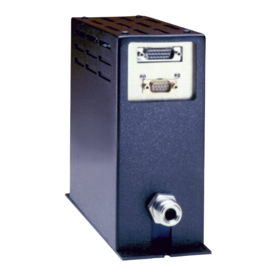
Page 19: Figure 4: Back View Of The 1152 Unit
Setup Chapter Two: Installation Temperature Deviation LED Test Points Temperature Switch : $ 5 1 ,1 * CONNECTOR PINOUTS Warning SIGNAL CONDITIONER HEATER SUPPLY VALVE TEST PT. +15 VDC Label 7.28 FLOW SIG.OUT NO CONNECTION VALVE CLOSE -15 VDC VALVE OPEN TEMP. -
Page 20: Mounting
Chapter Two: Installation Setup Mounting The 1152 unit has four mounting holes in its base plate as shown in Figure 6. The centers of these slots form a rectangle 8.75 inches long by 2.62 inches wide. Mounting Holes Mounting Holes Figure 6: Location of the Mounting Holes Follow these guidelines when mounting the 1152 unit: Warning... -
Page 21: Mechanical Installation
Setup Chapter Two: Installation Mechanical Installation Source Feed Line Temperature It is critically important for consistent system operation that the source feed lines be adequately heated and insulated. Remember, the coolest point in the system must be the source. The up- and down-stream shutoff valves must also be heated and insulated, since they are integral parts of the feed lines. - Page 22 Chapter Two: Installation Setup Source Feed Lines - Conductance To ensure that the 1152 unit will operate at full rated flow, use the largest possible I.D. piping. The 1152 unit is equipped with 8-VCR type male fittings to be used with ½ inch tubing. This diameter is adequate (ID ≥0.40”) for most installations.
-
Page 23: Electrical Information
We recommend the MKS 260PS-1 (MKS 260PS-3 for the high temperature option) combined with the MKS 246 Single Channel Power Supply/Readout. The current drawn from the 260PS-1/260PS-3 supply is directly related to the selected operating temperature. -
Page 24: Table 3: Signal (J15) Connector Pinout
Chapter Two: Installation Electrical Information Signal Connector The Signal Conditioner connector (J15) is a 15-pin male Type “D” connector. This connector contains the set point input, valve test point, and manual valve position pins. Signal (J15) Connector Pinout Pin Number Assignment Valve Test Point Flow Signal Output... -
Page 25: Table 4: Test Point Signals
Electrical Information Chapter Two: Installation Test Points The test points are located on the back of the unit, as shown in Figure 4, page 10. Test Point Signals Test Point Assignment Pressure 1 Pressure 2 Reserved Reserved Reserved Valve Test Point Reserved Flow Output Table 4: Test Point Signals... -
Page 26: Chapter Three: Overview
1152 unit. Changing the Range of the 1152 Unit MKS does not recommend that the Full Scale range of the instrument be changed in the field. This procedure requires disassembly of the instrument and may require replacement of the pressure transducers, the flow control valve, and/or the laminar flow element. -
Page 27: Calibration
Calibration Chapter Three: Overview Calibration Each 1152 MFC is calibrated before shipment for the range and the temperature that are marked on the identification tag. Power is applied to the internal heater circuit of the instrument, and it is allowed to stabilize at its operating temperature. The pressure transducers are checked for linearity and accuracy, and adjusted as necessary. -
Page 28: Analog Interface Signals
Chapter Three: Overview Analog Interface Signals Analog Interface Signals The 1152 MFC uses the analog set point input to provide “smart” features that otherwise would require separate signal lines and associated output control devices. 1. When the set point input is less than +10 mV the valve will be driven fully closed. This condition is similar to pulling the “CLOSE”... - Page 29 Analog Interface Signals Chapter Three: Overview This page intentionally left blank. Artisan Technology Group - Quality Instrumentation ... Guaranteed | (888) 88-SOURCE | www.artisantg.com...
-
Page 30: Chapter Four: Operation
Chapter Four: Operation How To Set the Temperature Chapter Four: Operation Warning Read and follow all safety messages listed in Safety Procedures and Precautions, page 1, BEFORE attempting to operate the 1152 unit. Failure to adhere to these messages could result in injury to personnel. Caution Prior to operating the 1152 MFC: 1. -
Page 31: Table 5: Operating Temperature Settings
Note The 1152 MFC is calibrated at a temperature specified at the time the unit was ordered. If the operating temperature must change, contact the MKS Applications group for a new set of calibration data. Artisan Technology Group - Quality Instrumentation ... Guaranteed | (888) 88-SOURCE | www.artisantg.com... -
Page 32: Temperature Indications
Chapter Four: Operation How To Set the Temperature Temperature Indications The temperature status of the 1152 MFC is indicated by both an LED and a relay. Table 6 lists the status of the LED and relay for various operating temperature ranges. The relay status is available on the 9-pin Power connector (J9). -
Page 33: How To Warm Up The 1152 Mfc
Failure to do so may damage the equipment. Note MKS recommends that the instrument be powered at all times. Continuous power to the unit eliminates the need to allow 4 to 5 hours for the unit to reach the operating temperature. -
Page 34: How To Zero The 1152 Mfc
Chapter Four: Operation How To Zero the 1152 MFC How To Zero the 1152 MFC Warning Read and follow all safety messages listed in Safety Procedures and Precautions, page 1, BEFORE attempting to zero the 1152 unit. Failure to adhere to these messages could result in injury to personnel. -
Page 35: How To Configure The Output
Note To configure a readout device without a gauge factor adjustment, to display sccm, an input divider may be used. Please note that MKS Types 112, 147, 246, and 247 have a gauge factor adjustment. Artisan Technology Group - Quality Instrumentation ... Guaranteed | (888) 88-SOURCE | www.artisantg.com... -
Page 36: Table 7: Gauge Factor Effect On The Display Range
Chapter Four: Operation How To Configure the Output Gauge Factor Effect on the Display Range Full Scale Flow Rate Gauge Factor Pot Range Full Scale Display Range 1.000 - 1.999 1.00 - 1.99 1.000 - 1.999 2.00 - 9.99 0.20 - 0.99 2.00 - 9.99 10.00 - 19.9 1.00 - 1.99... -
Page 37: Cautionary Notes
Note 2: MKS Supplied Power Supply/Display Equipment When the 1152 MFC is used with an MKS Type 147, 246, or 247C, Note 1 does not apply. The 147, 246, or 247C takes the flow signal from the 1152 MFC, zeroes it with the front panel zero pot, and sends it back to the controller section of the 1152 unit on pin 10 of the Signal (J15) connector. -
Page 38: Chapter Five: Troubleshooting
Chapter Five: Troubleshooting General Information Chapter Five: Troubleshooting General Information The 1152 MFC is optimized at the factory for specific application parameters. Consult the MKS Applications group if your application changes. Warning Read and follow all safety messages listed in Safety Procedures and Precautions, page 1, BEFORE attempting to troubleshoot the 1152 unit. - Page 39 1. Check line temperatures. or unit is non-linear, Evacuate overnight. or has erratic flow 2. Electronics malfunctioning. 2. Return unit to MKS for service. 3. Improper cable. 3. Check cable type. Also, check cable for damage. 4. System pressure too high.
-
Page 40: How To Check Valve Operation
Chapter Five: Troubleshooting General Information How To Check Valve Operation If the valve does not appear to be functioning properly, use this procedure to check the valve control electronics. If the electronics are functioning normally, the voltage at pin 1 of the Signal (J15) connector will correspond to the value in Table 9. - Page 41 General Information Chapter Five: Troubleshooting This page intentionally left blank. Artisan Technology Group - Quality Instrumentation ... Guaranteed | (888) 88-SOURCE | www.artisantg.com...
-
Page 42: Chapter Six: Maintenance
If, after performing the checks listed above, it is determined that cleaning is necessary, disassembly of the instrument will be required. You must send the unit back to MKS for disassembly and cleaning. Prior to any return, the instrument MUST be purged of all contaminants. - Page 43 Cleaning and Repair Chapter Six: Maintenance This page intentionally left blank. Artisan Technology Group - Quality Instrumentation ... Guaranteed | (888) 88-SOURCE | www.artisantg.com...
-
Page 44: Appendix A: Product Specifications
An overall metal braided shielded cable, properly grounded at both ends, is required during use. Contact MKS Applications group for information on specific applications. The 1152 MFC may be mounted in any position, however, MKS does not recommend mounting it in an upside-down position. -
Page 45: Electrical Specifications
Electrical Specifications Appendix A: Product Specifications Weight 7.9 lbs (3.59 kg) Electrical Specifications Heater Supply Power ±15 VDC (±2%) @1.5 Amp maximum; @ 3.0 Amp for the optional high temperature unit Regulation Line 0.1% Load 1.0% Ripple 50 millivolts (peak-to-peak) Signal Conditioner Power ±15 VDC (±2%) @ 0.28 Amp maximum... -
Page 46: Appendix B: Calibration Data Sheet
Typical Calibration Data Sheet Each 1152 MFC is shipped with a Calibration Data Sheet, as shown below. This sheet contains important information on the specific application for which the 1152 MFC was designed. 1152C FLOW CALIBRATION DATA CUSTOMER: DATE: 11/01/96... -
Page 47: Figure 10: Example Calibration Graph
Appendix B: Calibration Data Sheet 1152C FLOW CALIBRATION DATA Serial #: FLOW SCCM 5.00 4.00 4.00 3.60 3.20 3.00 2.80 2.40 2.00 2.00 1.60 2.20 1.97 1.20 1.74 1.53 1.31 1.00 0.80 1.08 0.86 0.63 0.40 0.42 0.19 0.00 0.00 0.50 1.00 1.50 2.00 2.50 3.00 3.50 4.00 4.50 5.00... -
Page 48: Index
Index Index Accuracy, 35 Gauge factor, 27 Analog interface, 19 Heating, 12 Cables, 6 High Temperature option, 14 Calibration Data Sheet, 25, 37 CE Mark, 6, 35 Interface cables, 6 Cleaning, 33 Conductance, 13 Connectors, 14–15 LED, 23 Customer support, 4 Maintenance, 33 Decomposition, 12, 21 Manual organization, 4... - Page 49 Index Readout, 26, 28 Repair, 33 Returning the product, 4, 5 Returns, 33 RFI, 19 Safety procedures and precautions, 1–2 Set point, 19 Source material, 17 Specifications, 35–36 Temperature, 9, 17, 21–24 Temperature control, 12 Temperature status, 23 Troubleshooting, 29 Valve, 31 Valve position, 15, 16 Warm up, 24...
Need help?
Do you have a question about the 1152C and is the answer not in the manual?
Questions and answers