
Related Manuals for Microchip Technology Digital Power Starter Kit


Summary of Contents for Microchip Technology Digital Power Starter Kit
- Page 1 Digital Power Starter Kit User’s Guide 2012 Microchip Technology Inc. DS52078A Arrow.com. Downloaded from...
- Page 2 Select Mode, Total Endurance, TSHARC, UniWinDriver, WiperLock and ZENA are trademarks of Microchip Technology Incorporated in the U.S.A. and other countries. SQTP is a service mark of Microchip Technology Incorporated in the U.S.A. All other trademarks mentioned herein are property of their respective companies.
- Page 3 2012 Microchip Technology Inc. DS52078A-page 3 Arrow.com. Arrow.com. Arrow.com. Downloaded from Downloaded from Downloaded from...
- Page 4 Digital Power Starter Kit User’s Guide NOTES: 2012 Microchip Technology Inc. DS52078A-page 4 Arrow.com. Arrow.com. Arrow.com. Arrow.com. Downloaded from Downloaded from Downloaded from Downloaded from...
-
Page 5: Safety Notice
Do not move during operation and avoid direct contact with the bottom layer of the board. • The Digital Power Starter Kit should not be connected or operated if there is any apparent damage to the unit. - Page 6 Digital Power Starter Kit User’s Guide NOTES: 2012 Microchip Technology Inc. DS52078A-page 6 Arrow.com. Arrow.com. Arrow.com. Arrow.com. Arrow.com. Arrow.com. Downloaded from Downloaded from Downloaded from Downloaded from Downloaded from Downloaded from...
-
Page 7: Table Of Contents
DIGITAL POWER STARTER KIT USER’S GUIDE Table of Contents Safety Notice ......................... 5 Preface ........................... 9 Chapter 1. Introduction 1.1 Overview ...................... 15 1.2 Kit Contents ....................15 1.3 Starter Kit Functionality and Features ............16 1.4 Electrical Specifications ................18 Chapter 2. - Page 8 Digital Power Starter Kit User’s Guide NOTES: 2012 Microchip Technology Inc. DS52078A-page 8 Arrow.com. Arrow.com. Arrow.com. Arrow.com. Arrow.com. Arrow.com. Arrow.com. Arrow.com. Downloaded from Downloaded from Downloaded from Downloaded from Downloaded from Downloaded from Downloaded from Downloaded from...
-
Page 9: Preface
• Customer Support • Document Revision History DOCUMENT LAYOUT This user’s guide provides an overview of the Digital Power Starter Kit. The document is organized as follows: • Chapter 1. “Introduction” – This chapter introduces the Digital Power Starter Kit and provides a brief overview of its features. - Page 10 Digital Power Starter Kit User’s Guide CONVENTIONS USED IN THIS GUIDE This manual uses the following documentation conventions: DOCUMENTATION CONVENTIONS Description Represents Examples Arial font: ® Italic characters Referenced books MPLAB IDE User’s Guide Emphasized text ...is the only compiler...
- Page 11 Preface RECOMMENDED READING This user’s guide describes how to use the Digital Power Starter Kit. The device-specific data sheets contain current information on programming the specific microcontroller or digital signal controller devices. The following Microchip documents are available and recommended as supplemental reference resources: ®...
- Page 12 Digital Power Starter Kit User’s Guide THE MICROCHIP WEB SITE Microchip provides online support via our web site at www.microchip.com. This web site is used as a means to make files and information easily available to customers. Accessible by using your favorite Internet browser, the web site contains the following information: •...
- Page 13 Technical support is available through the web site at: http://support.microchip.com DOCUMENT REVISION HISTORY Revision A (June 2012) This is the initial released version of the document. 2012 Microchip Technology Inc. DS52078A-page 13 Arrow.com. Arrow.com. Arrow.com. Arrow.com.
- Page 14 Digital Power Starter Kit User’s Guide NOTES: 2012 Microchip Technology Inc. DS52078A-page 14 Arrow.com. Arrow.com. Arrow.com. Arrow.com. Arrow.com. Arrow.com. Arrow.com. Arrow.com. Arrow.com. Arrow.com. Arrow.com. Arrow.com. Arrow.com. Arrow.com. Downloaded from Downloaded from Downloaded from Downloaded from Downloaded from Downloaded from...
-
Page 15: Chapter 1. Introduction
DIGITAL POWER STARTER KIT USER’S GUIDE Chapter 1. Introduction This chapter introduces the Digital Power Starter Kit and provides an overview of its features. The topics covered include: • Kit Contents • Starter Kit Functionality and Features • Electrical Specifications... -
Page 16: Starter Kit Functionality And Features
Digital Power Starter Kit User’s Guide STARTER KIT FUNCTIONALITY AND FEATURES The Digital Power Starter Kit is a power supply board that consists of one independent DC/DC synchronous Buck converter and one independent DC/DC Boost converter. Figure 1-1 illustrates a high-level block diagram of the Starter Kit. - Page 17 1.3.3 Starter Kit Power • +9V power connector (J2) supplies power to the Digital Power Starter Kit • USB connection jack (J5) supplies power/connection to the on-board debugger • Buck and Boost converters are both operated in Voltage mode (default), but can also be reprogrammed to operate in Average Current or Peak Current Control mode ...
-
Page 18: Electrical Specifications
Digital Power Starter Kit User’s Guide ELECTRICAL SPECIFICATIONS TABLE 1-1: DC INPUT RATING (J2) Parameter Minimum Typical Maximum Unit Voltage Current — — TABLE 1-2: BUCK CONVERTER ELECTRICAL SPECIFICATIONS Parameter Minimum Typical Maximum Unit Output Voltage (default programmed) — —... -
Page 19: Chapter 2. Hardware
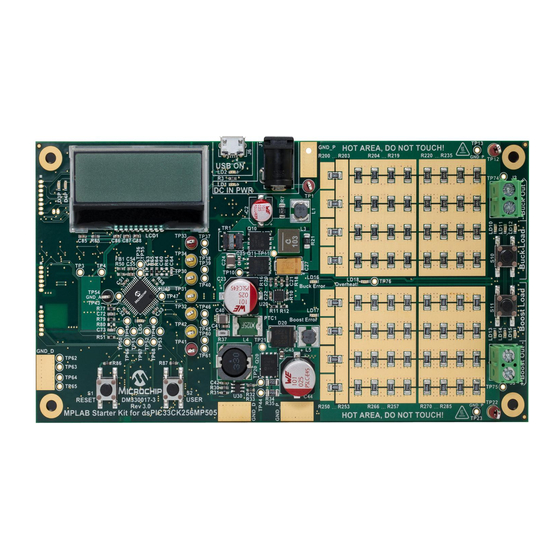
DIGITAL POWER STARTER KIT USER’S GUIDE Chapter 2. Hardware This chapter describes the hardware components of the Digital Power Starter Kit. Topics covered include: • Top Assembly • Signal Configuration • Application Components • Board Connectors • Indicators and Human Interfaces •... - Page 20 Digital Power Starter Kit User’s Guide TABLE 2-1: DIGITAL POWER STARTER KIT COMPONENTS (TOP) Number Description dsPIC33FJ09GS302 Digital Signal Controller (DSC) (U3) 9V Power Connector (J2) 2x16 Character LCD Boost Converter Stage Buck Converter Stage Push Button (SW1) Potentiometers (P1 and P2) Voltage Regulator (3.3V)
-
Page 21: Signal Configuration
Hardware SIGNAL CONFIGURATION Table 2-3 provides a full list of the dsPIC33FJ09GS302 DSC connections and a brief functional description of the pins used in the Digital Power Starter Kit. TABLE 2-3: dsPIC33FJ09GS302 CONFIGURATION DETAILS dsPIC33FJ09GS302 Digital Power Starter Kit Description/Function... -
Page 22: Application Components
Digital Power Starter Kit User’s Guide APPLICATION COMPONENTS Table 2-4 describes the application components that are available on the Digital Power Starter Kit (see Figure 2-1 Figure 2-2 for component locations). TABLE 2-4: APPLICATION COMPONENTS Component Label Item Description Figure 2-1... -
Page 23: Board Connectors
Push button switch, which is connected to the RB8 port pin. When momentarily pressed, the LCD measurement and board status information is changed. Power-on status LED, which indicates that the Digital Power Starter Kit is powered by the 9V supply. -
Page 24: Test Points
Digital Power Starter Kit User’s Guide TEST POINTS Table 2-7 describes the test points that are available on the Digital Power Starter Kit. Figure 2-3 for test point locations. TABLE 2-7: TEST POINTS Test Point Description 9V Power Supply test point... -
Page 25: Power Rating Of Converter Stages
Hardware POWER RATING OF CONVERTER STAGES The Digital Power Starter Kit is designed to be a self-contained power supply board with variable 5W loads connected to each DC/DC converter. 2.7.1 BUCK CONVERTER The Buck converter stage is rated for a maximum power output of 5W to the dedicated on-board resistive load. -
Page 26: Programmer/Debugger
0.10 0.05 0.00 Output Voltage, V PROGRAMMER/DEBUGGER The Digital Power Starter Kit includes an on-board programmer/debugger circuit that provides connectivity over USB. This circuit is hard-wired to the dsPIC DSC device to provide ICSP™ debugging/programming capability. 2.8.1 Programmer/Debugger Components Table 2-8... -
Page 27: Chapter 3. Demonstration Program Operation
Proportional-Integral-Derivative (PID) control of the output voltage for the two DC/DC converter circuits on board the Digital Power Starter Kit. This code can be downloaded from the Microchip web site (www.microchip.com). This section covers the following topics: •... - Page 28 Digital Power Starter Kit User’s Guide FIGURE 3-1: SMPS DEMONSTRATION PROGRAM FLOW CHART Start Initialization Routines: • Peripherals – ADC, PWM, Timers, GPIO, LCD, etc. • Variables – PID Gain Terms, Data Buffers • Interrupts – ADC, Timers • Set Soft Start Flag...
-
Page 29: Code Demonstration
Refer to the Readme files located in each code example folder for details on what each code example demonstrates. Check the Microchip web site (www.microchip.com/SMPS) for the latest updates to the code examples and for additional code examples. 2012 Microchip Technology Inc. DS52078A-page 29 Arrow.com. Arrow.com. - Page 30 Digital Power Starter Kit User’s Guide NOTES: 2012 Microchip Technology Inc. DS52078A-page 30 Arrow.com. Arrow.com. Arrow.com. Arrow.com. Arrow.com. Arrow.com. Arrow.com. Arrow.com. Arrow.com. Arrow.com. Arrow.com. Arrow.com. Arrow.com. Arrow.com. Arrow.com. Arrow.com. Arrow.com. Arrow.com. Arrow.com. Arrow.com. Arrow.com. Arrow.com. Arrow.com. Arrow.com. Arrow.com. Arrow.com.
-
Page 31: Appendix A. Board Layout And Schematics
DIGITAL POWER STARTER KIT USER’S GUIDE Appendix A. Board Layout and Schematics FIGURE A-1: DIGITAL POWER STARTER KIT LAYOUT (TOP) 2012 Microchip Technology Inc. DS52078A-page 31 Arrow.com. Arrow.com. Arrow.com. Arrow.com. Arrow.com. Arrow.com. Arrow.com. Arrow.com. Arrow.com. Arrow.com. Arrow.com. Arrow.com. Arrow.com. - Page 32 Digital Power Starter Kit User’s Guide FIGURE A-2: DIGITAL POWER STARTER KIT LAYOUT (BOTTOM) 2012 Microchip Technology Inc. DS52078A-page 32 Arrow.com. Arrow.com. Arrow.com. Arrow.com. Arrow.com. Arrow.com. Arrow.com. Arrow.com. Arrow.com. Arrow.com. Arrow.com. Arrow.com. Arrow.com. Arrow.com. Arrow.com. Arrow.com. Arrow.com. Arrow.com. Arrow.com.
- Page 33 Board Layout and Schematics FIGURE A-3: DIGITAL POWER STARTER KIT SCHEMATIC 2012 Microchip Technology Inc. DS52078A-page 33 Arrow.com. Arrow.com. Arrow.com. Arrow.com. Arrow.com. Arrow.com. Arrow.com. Arrow.com. Arrow.com. Arrow.com. Arrow.com. Arrow.com. Arrow.com. Arrow.com. Arrow.com. Arrow.com. Arrow.com. Arrow.com. Arrow.com. Arrow.com. Arrow.com. Arrow.com.
- Page 34 Digital Power Starter Kit User’s Guide FIGURE A-4: DIGITAL POWER STARTER KIT SCHEMATIC (BOOST CONVERTER) 2012 Microchip Technology Inc. DS52078A-page 34 Arrow.com. Arrow.com. Arrow.com. Arrow.com. Arrow.com. Arrow.com. Arrow.com. Arrow.com. Arrow.com. Arrow.com. Arrow.com. Arrow.com. Arrow.com. Arrow.com. Arrow.com. Arrow.com. Arrow.com. Arrow.com.
- Page 35 Board Layout and Schematics FIGURE A-5: DIGITAL POWER STARTER KIT SCHEMATIC (BUCK CONVERTER) 2012 Microchip Technology Inc. DS52078A-page 35 Arrow.com. Arrow.com. Arrow.com. Arrow.com. Arrow.com. Arrow.com. Arrow.com. Arrow.com. Arrow.com. Arrow.com. Arrow.com. Arrow.com. Arrow.com. Arrow.com. Arrow.com. Arrow.com. Arrow.com. Arrow.com. Arrow.com. Arrow.com.
- Page 36 Digital Power Starter Kit User’s Guide NOTES: 2012 Microchip Technology Inc. DS52078A-page 36 Arrow.com. Arrow.com. Arrow.com. Arrow.com. Arrow.com. Arrow.com. Arrow.com. Arrow.com. Arrow.com. Arrow.com. Arrow.com. Arrow.com. Arrow.com. Arrow.com. Arrow.com. Arrow.com. Arrow.com. Arrow.com. Arrow.com. Arrow.com. Arrow.com. Arrow.com. Arrow.com. Arrow.com. Arrow.com. Arrow.com.
- Page 37 NOTES: 2012 Microchip Technology Inc. DS52078A-page 37 Arrow.com. Arrow.com. Arrow.com. Arrow.com. Arrow.com. Arrow.com. Arrow.com. Arrow.com. Arrow.com. Arrow.com. Arrow.com. Arrow.com. Arrow.com. Arrow.com. Arrow.com. Arrow.com. Arrow.com. Arrow.com. Arrow.com. Arrow.com. Arrow.com. Arrow.com. Arrow.com. Arrow.com. Arrow.com. Arrow.com. Arrow.com. Arrow.com. Arrow.com. Arrow.com. Arrow.com. Arrow.com.
-
Page 38: Worldwide Sales And Service
Fax: 66-2-694-1350 Mississauga, Ontario, Canada China - Xiamen Tel: 905-673-0699 Tel: 86-592-2388138 Fax: 905-673-6509 Fax: 86-592-2388130 China - Zhuhai Tel: 86-756-3210040 11/29/11 Fax: 86-756-3210049 2012 Microchip Technology Inc. DS52078A-page 38 Arrow.com. Arrow.com. Arrow.com. Arrow.com. Arrow.com. Arrow.com. Arrow.com. Arrow.com. Arrow.com. Arrow.com.
Need help?
Do you have a question about the Digital Power Starter Kit and is the answer not in the manual?
Questions and answers