Table of Contents
Advertisement
Quick Links
SAM E54 Xplained Pro
SAM E54 Xplained Pro User's Guide
Preface
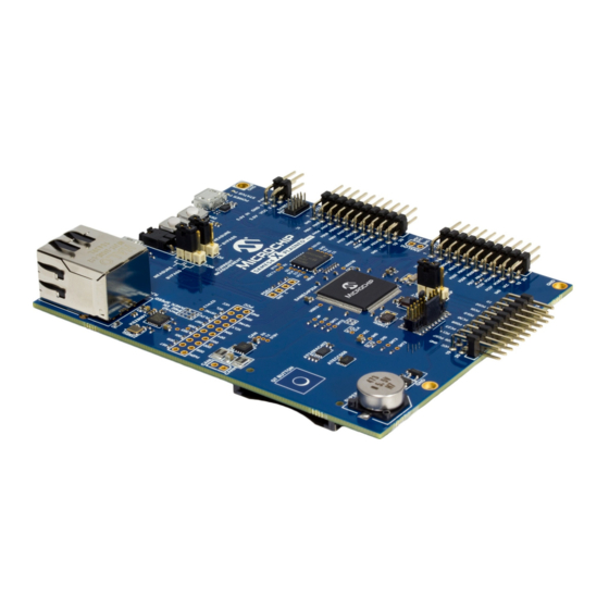
The SAM E54 Xplained Pro evaluation kit is a hardware platform to evaluate the ATSAME54P20A
microcontroller.
Supported by the integrated development platform Atmel Studio, the kit provides easy access to the
features of the ATSAME54P20A and explains how to integrate the device in a custom design.
The Xplained Pro MCU series evaluation kits include an on-board Embedded Debugger, and no external
tools are necessary to program or debug the ATSAME54P20A.
The Xplained Pro extension kits offers additional peripherals to extend the features of the board and ease
the development of custom designs.
DS70005321A-page 1
©
2017 Microchip Technology Inc.
Advertisement
Table of Contents

Related Manuals for Microchip Technology SAM E54 Xplained Pro


Summary of Contents for Microchip Technology SAM E54 Xplained Pro
-
Page 1: Preface
SAM E54 Xplained Pro SAM E54 Xplained Pro User's Guide Preface The SAM E54 Xplained Pro evaluation kit is a hardware platform to evaluate the ATSAME54P20A microcontroller. Supported by the integrated development platform Atmel Studio, the kit provides easy access to the features of the ATSAME54P20A and explains how to integrate the device in a custom design. -
Page 2: Table Of Contents
SAM E54 Xplained Pro Table of Contents Preface..........................1 1. Object of Declaration....................4 2. Introduction........................5 2.1. Features............................5 2.2. Kit Overview..........................6 3. Getting Started......................7 3.1. Xplained Pro Quick Start......................7 3.2. Design Documentation and Relevant Links................. 7 4. - Page 3 SAM E54 Xplained Pro 5.3.7. Ethernet........................26 5.3.8. AT24MAC402......................27 5.3.9. ATECC508A........................ 28 5.3.10. QSPI Flash........................28 5.3.11. S Signals........................29 5.4. Embedded Debugger Implementation..................30 5.4.1. Serial Wire Debug......................30 5.4.2. Virtual COM Port......................30 5.4.3. Data Gateway Interface....................30 5.4.4. XAM Configuration.......................31 5.5.
-
Page 4: Object Of Declaration
For information regarding the exclusive, limited warranties applicable to Microchip products, please see Microchip’s standard terms and conditions of sale, which are printed on our sales documentation and available at www.microchip.com. Signed for and on behalf of Microchip Technology Inc. at Chandler, Arizona, USA. DS70005321A-page 4 ©... -
Page 5: Introduction
SAM E54 Xplained Pro Introduction Features • ATSAME54P20A microcontroller • One mechanical reset button • One mechanical programmable button ® • One QTouch PTC button • One yellow user LED • 256 Mb QSPI Flash ™ • ATECC508 CryptoAuthentication device ™... -
Page 6: Kit Overview
SAM E54 Xplained Pro Kit Overview The SAM E54 Xplained Pro evaluation kit is a hardware platform to evaluate the ATSAME54P20A. The kit offers a set of features that enables the ATSAME54P20A user to get started with the SAM E54 peripherals right away and to get an understanding of how to integrate the device in their own design. -
Page 7: Getting Started
SAM E54 Xplained Pro Getting Started Xplained Pro Quick Start Steps to start exploring the Xplained Pro platform: Download and install Atmel Studio. Launch Atmel Studio. Connect the DEBUG USB port on the evaluation kit to the computer using a USB cable (Standard- A to Micro-B or Micro-AB). - Page 8 Interface found on Xplained Pro boards and COM Ports. • SAM E54 Xplained Pro website - Kit information, latest user guide and design documentation. • SAM E54 Xplained Pro on Microchip Direct - Purchase this kit on Microchip Direct. DS70005321A-page 8 © 2017 Microchip Technology Inc.
-
Page 9: Xplained Pro
DGI. The EDBG controls two LEDs on the SAM E54 Xplained Pro: a power LED and a status LED. The table below shows how the LEDs are controlled in different operation modes. -
Page 10: Xplained Pro Analog Module (Xam)
SAM E54 Xplained Pro Table 4-1. EDBG LED Control Mode Power LED Status LED Normal mode The power LED is on when Activity indicator, the LED flashes power is applied to the board. when any communication happens to the EDBG. Bootloader mode (idle) The power LED and the status LED blink simultaneously. -
Page 11: Edbg Interface
SAM E54 Xplained Pro – Analog-to-Digital Converter – Signal processing – Control/communication interface to the EDBG The current measurement front-end is a high side shunt measurement with a pre-amplifier and a second active filter stage with gain as shown in Figure 4-1. -
Page 12: Hardware Identification System
3600 Maximum Current [mA] uint16_t Power Sources The SAM E54 Xplained Pro kit can be powered by several power sources, as listed in the table below. Table 4-4. Power Sources for SAM E54 Xplained Pro Power Source Voltage Requirements Current Requirements... -
Page 13: Xplained Pro Headers And Connectors
SAM E54 Xplained Pro Embedded Debugger USB. Target USB. Info: External power is required when 500mA from a USB connector is not enough to power the board with possible extension boards. A connected USB device in a USB host application might easily exceed this limit. -
Page 14: Xplained Pro Power Header
Xplained Pro Power Header The power header can be used to connect external power to the SAM E54 Xplained Pro kit. The kit automatically detects and switches to any external power if supplied. The power header can also be used to supply power to external peripherals or extension boards. -
Page 15: Hardware User Guide
Hardware User Guide Power Distribution SAM E54 Xplained Pro has three power sources: EDBG USB, Target USB, and/or external 5.0V. The kit will automatically select a source to draw power from. The kit has two on-board 3.3V voltage regulators, one for the EDBG and XAM, and one for the ATSAME54P20A and other peripherals. -
Page 16: Xplained Pro Standard Extension Headers
SAM E54 Xplained Pro Figure 5-2. SAM E54 Xplained Pro Connector Overview 5.2.1 Xplained Pro Standard Extension Headers The Xplained Pro extension headers EXT1, EXT2, and EXT3 offer access to the I/O of the microcontroller to expand the board, for example, by connecting extensions to the board. These headers are based on the standard Xplained Pro extension header specification and the connections are shown in the table below. - Page 17 SAM E54 Xplained Pro Table 5-1. Extension Header EXT1 EXT1 pin SAM E54 Function Shared functionality 1 [ID] Communication line to the ID chip on an extension board 2 [GND] Ground 3 [ADC(+)] PB04 ADC1/AIN[6] 4 [ADC(-)] PB05 ADC1/AIN[7] 5 [GPIO1]...
- Page 18 SAM E54 Xplained Pro EXT2 pin SAM E54 Function Shared functionality 8 [PWM(-)] PB15 TCC4/WO[5] 9 [IRQ/GPIO] PD00 IRQ0/GPIO 10 [SPI_SS_B/GPIO] PB02 GPIO 11 [TWI_SDA] PD08 SERCOM7 PAD[0] I²C SDA AT24MAC402, ATECC508, PCC, EXT3, and EDBG DGI 12 [TWI_SCL] PD09 SERCOM7 PAD[1] I²C SCL...
-
Page 19: Sd/Sdio Card
Power for extension board 5.2.2 SD/SDIO Card SAM E54 Xplained Pro has one standard SD card connector which is connected to the SD/MMC Host Controller (SDHC) of the SAM E54. The table below lists all I/O-lines connected to the SD card connector. - Page 20 SAM E54 Xplained Pro Tip: The DEN1 and DEN2 signals connected to VSYNC and HYSNC on the PCC camera connector are used to tell the PCC module when there is valid data to sample on the data pins. If interrupts are required when the DEN1 and DEN2 signals changes, the I/O pins (PA12 and PA13) has to be multiplexed to the EIC function in the GPIO module.
-
Page 21: Position Decoder
5.2.4 Position Decoder SAM E54 Xplained Pro has a header footprint for the position decoder module. The PDEC can be used for quadrature, hall, and counter decoding. Info: External pull-ups are mounted on the three signal lines for use with passive quadrature encoders. -
Page 22: Cortex Debug Connector
5.2.8 Cortex Debug Connector SAM E54 Xplained Pro has a 10-pin 50-mil Cortex Debug Connector with SWD that can be used to attach external debuggers to the ATSAME54P20A. Microchip debugging tools like the Atmel-ICE and Power Debugger can connect directly to this connector. -
Page 23: Current Measurement Header
An angled 1x2, 100-mil pin header marked with the MCU current measurement is located at the upper edge of the SAM E54 Xplained Pro. All power to the ATSAME54P20A is exclusively routed through this header (excluding power to headers and peripherals). To measure the power consumption of the device, remove the jumper and replace it with an ammeter. -
Page 24: Peripherals
Crystals SAM E54 Xplained Pro has a 32.768 kHz and a 12 MHz crystal that can be used as clock source for the SAM E54 device. There are cut-straps located close to the crystals that can be used to measure the oscillator safety factor. -
Page 25: Led
PB31 EDBG GPIO3 5.3.3 There is one yellow LED available on the SAM E54 Xplained Pro board that can be turned ON and OFF. The LED can be activated by driving the connected I/O line to GND. Table 5-15. LED Connection... -
Page 26: Can
ATSAME54P20A has a built-in 10/100Mbps Ethernet IEEE 802.3 compatible MAC with RMII interface. The MAC also supports energy efficient Ethernet (IEEE 802.3az). SAM E54 Xplained Pro connects the MAC to a Micrel KSZ8091RNACA RMII physical-layer transceiver (PHY), with IEEE 802.3az support, which is connected to one RJ45 Ethernet connector. -
Page 27: At24Mac402
Auto negotiation enabled and 100Mbps link speed enabled 5.3.8 AT24MAC402 SAM E54 Xplained Pro features one external AT24MAC402 serial EEPROM with a EIA-48 MAC address connected to the SAM E54 through I C. This device contain a MAC address for use with the Ethernet interface. -
Page 28: Atecc508A
5.3.10 QSPI Flash The SAM E54 Xplained Pro features one external MICRON, N25Q256A, 256Mbit QSPI NOR Flash Memory. QSPI Flash access can be configured in the QSPI module in the SAM E54, with support for XIP to run firmware directly from external flash. The table below lists all I/O-lines connected to the QSPI Flash. -
Page 29: I 2 S Signals
There is no on-board IC connected to this module, but the signals are available on the different pin- headers on the kit as shown in the table below. Table 5-23. I S Signals on SAM E54 Xplained Pro Microcontroller Pin S Signal... -
Page 30: Embedded Debugger Implementation
SAM E54 Xplained Pro Embedded Debugger Implementation SAM E54 Xplained Pro contain an Embedded Debugger (EDBG) that can be used to program and debug the ATSAME54P20A using Serial Wire Debug (SWD). The Embedded Debugger also includes a Virtual Com port interface over UART, a Data Gateway Interface over SPI, and I C, and it includes four of the SAM E54 GPIOs. -
Page 31: Xam Configuration
5.4.4 XAM Configuration On the SAM E54 Xplained Pro the MCU and the MCU peripherals (e.g. extensions) are powered by its own regulator as shown in the figure below. All other parts of the board, mainly embedded debugger and accompanying Xplained Pro Analog Module (XAM), are powered from a separate regulator. The current to the MCU and peripherals can be measured by connecting them to the XAM output through jumper settings. -
Page 32: Kit Modifications
XAM. Place both jumpers on "I/O" and "MCU" headers in the "MEASURE" position. Kit Modifications SAM E54 Xplained Pro has several resistors that can be used to disconnect I/O pins of the ATSAME54P20A from connectors and on-board ICs, and to disconnect power signals. DS70005321A-page 32 ©... - Page 33 SAM E54 Xplained Pro Info: Note that there are some resistors that aren't mounted by default on the kit listed in the table below. Table 5-29. Resistors Designat Value From Comment J101 cut-strap VCC_P3V3 VCC_P3V3_CM_IN ATSAME54P20A, peripherals and connectors power supply R101 0Ω...
- Page 34 SAM E54 Xplained Pro Designat Value From Comment R824 0Ω EDBG SWDIO PA31 SWDIO R827 0Ω EDBG SWO PB30 SWO R808 0Ω EDBG CDC RX PB25 UART TX EDBG CDC and DGI interfaces to the ATSAME54P20A R809 330Ω EDBG CDC TX...
- Page 35 SAM E54 Xplained Pro Figure 5-4. Assembly Drawing Top DS70005321A-page 35 © 2017 Microchip Technology Inc.
-
Page 36: Enable Pcc Header
5.5.1 Enable PCC Header header on the SAM E54 Xplained Pro board is by default not functional due to shared connections with Ethernet, QTouch, SD Card, EXT1, and EXT2. To modify the kit to fully enable the PCC header, do the following: •... -
Page 37: Operation At Other Voltages
Operation at Other Voltages The SAM E54 Xplained Pro board is operated at 3.3V by default, but it also has the possibility of running at lower voltages from an external supply. The EDBG is designed to run from a 3.3V supply and won't work on other voltages, therefore all connections from the EDBG and the on board 3.3V regulator to the... -
Page 38: Low-Power Mode
SAM E54 Xplained Pro Figure 5-6. SAM E54 Xplained Pro EDBG Disconnect Figure 5-7. SAM E54 Xplained Pro Current Measurement Headers Related Links Xplained Pro Power Header Cortex Debug Connector Connectors Low-Power Mode Acquiring the lowest power consumption of the device requires some specific settings of the GPIOs in relation to the connected peripherals. -
Page 39: Kit Specific Data
SAM E54 Xplained Pro Kit Specific Data One of the Flash user pages in the EDBG is programmed with data specific to the SAM E54 Xplained Pro. The data can be read through the I C interface connected to the EDBG from the target application. -
Page 40: Appendix
SAM E54 Xplained Pro Appendix Getting Started with IAR ® ® IAR Embedded Workbench for ARM is a proprietary, high-efficiency compiler not based on GCC. The ™ programming and debugging of Xplained Pro kits are supported in IAR Embedded Workbench for ARM using the common CMSIS-DAP interface. - Page 41 SAM E54 Xplained Pro Figure 7-2. Select Debugger Figure 7-3. Configure Flash Loader DS70005321A-page 41 © 2017 Microchip Technology Inc.
- Page 42 SAM E54 Xplained Pro Figure 7-4. Configure Reset Figure 7-5. Configure Interface DS70005321A-page 42 © 2017 Microchip Technology Inc.
-
Page 43: Connecting External Debuggers To An Xplained Pro Board
SAM E54 Xplained Pro Connecting External Debuggers to an Xplained Pro Board The Xplained Pro kits that features a 10-pin 50mil debug connector can use external debug tools like ™ SAM-ICE or Atmel-ICE instead of the built-in EDBG. Evaluation kits with devices using the SWD... - Page 44 SAM E54 Xplained Pro Figure 7-7. SAM-ICE using an Atmel-ICE Adapter Important: If contention with the on-board EDBG occurs, power the Xplained Pro board from another input like the external power header or from the target USB. Physically removing the connection between the EDBG and the debug header by removing 0Ω...
-
Page 45: Hardware Revision History And Known Issues
Revision 4 Revision 4 is the initially released revision. The Early Adopter version of ATSAME54P20A is mounted on revision 4 of SAM E54 Xplained Pro. 8.3.1 VBAT Pin There is an issue with the VBAT pin in ATSAME54P20A revision A0. When VBAT > VDDIO there is a current over-consumption rendering the on-board super-capacitor backup solution unusable. -
Page 46: 32.768 Khz Crystal
8.3.2 32.768 KHz Crystal The 32.768 KHz crystal mounted on revision 4 of SAM E54 Xplained Pro is a Kyocera Crystal Device Corporation ST3215SB32768E0HPWBB 9 pF crystal. The external matching capacitors C300 and C301 are 15 pF. The crystal is matched to be driven by the SAM E54 in standard mode. -
Page 47: Document Revision History
SAM E54 Xplained Pro Document Revision History Date Comment 07/2017 Initial document release. DS70005321A-page 47 © 2017 Microchip Technology Inc. -
Page 48: The Microchip Web Site
SAM E54 Xplained Pro The Microchip Web Site Microchip provides online support via our web site at http://www.microchip.com/. This web site is used as a means to make files and information easily available to customers. Accessible by using your favorite Internet browser, the web site contains the following information: •... -
Page 49: Legal Notice
SQTP is a service mark of Microchip Technology Incorporated in the U.S.A. Silicon Storage Technology is a registered trademark of Microchip Technology Inc. in other countries. GestIC is a registered trademark of Microchip Technology Germany II GmbH & Co. KG, a subsidiary of Microchip Technology Inc., in other countries. -
Page 50: Quality Management System Certified By Dnv
SAM E54 Xplained Pro ISBN: 978-1-5224-1929-7 Quality Management System Certified by DNV ISO/TS 16949 Microchip received ISO/TS-16949:2009 certification for its worldwide headquarters, design and wafer fabrication facilities in Chandler and Tempe, Arizona; Gresham, Oregon and design centers in California ®... -
Page 51: Worldwide Sales And Service
Thailand - Bangkok Sweden - Stockholm Tel: 408-735-9110 Tel: 86-29-8833-7252 Tel: 66-2-694-1351 Tel: 46-8-5090-4654 Tel: 408-436-4270 Fax: 86-29-8833-7256 Fax: 66-2-694-1350 UK - Wokingham Canada - Toronto Tel: 44-118-921-5800 Tel: 905-695-1980 Fax: 44-118-921-5820 Fax: 905-695-2078 DS70005321A-page 51 © 2017 Microchip Technology Inc. - Page 52 Mouser Electronics Authorized Distributor Click to View Pricing, Inventory, Delivery & Lifecycle Information: Microchip ATSAME54-XPRO...
Need help?
Do you have a question about the SAM E54 Xplained Pro and is the answer not in the manual?
Questions and answers