Table of Contents
Advertisement
Quick Links
SAMR34 Getting Started LoRaWAN USB_CDC example Quick Start Guide
Introduction
This document is intended as a guide to help you understand the features, and to describe how to use the example
project: SAMR34 Getting Started LoRaWAN USB_CDC
Table of Contents
Contents
SAMR34 Getting Started LoRaWAN USB_CDC example Quick Start Guide ................................................. 1
Table of Contents .................................................................................................................................. 1
1.
Overview .................................................................................................................................... 2
1.1
Supported hardware platforms and IDEs ................................................................................... 2
2.
Development environment ......................................................................................................... 3
2.1.
Atmel Studio 7 ........................................................................................................................... 3
2.2.
SAMR34 Xplained Pro [DM320111] ......................................................................................... 3
3.
Stack Configurations .................................................................................................................. 4
4.
Building applications in Atmel Studio ......................................................................................... 5
4.1.
Setting Project / Properties ........................................................................................................ 5
5.
Hardware environment setup ..................................................................................................... 6
5.1.
Supported platform and eval board............................................................................................ 6
6.
LoRaWAN USB_CDC example project ................................................................................... 7
6.1
Changing Data Rate / Spreading factor ................................................................................... 10
6.2
Changing TX power index ....................................................................................................... 11
6.3
Restoring to default (initial) Data Rate and TX power levels .................................................... 12
6.4
Manual PushButton sensor transmission ................................................................................. 13
6.5
Restarting / Restoring configuration upon power cycle/reset ................................................... 14
1
Advertisement
Table of Contents

Related Manuals for Microchip Technology SAMR34J18B


Summary of Contents for Microchip Technology SAMR34J18B
-
Page 1: Table Of Contents
SAMR34 Getting Started LoRaWAN USB_CDC example Quick Start Guide Introduction This document is intended as a guide to help you understand the features, and to describe how to use the example project: SAMR34 Getting Started LoRaWAN USB_CDC Table of Contents Contents SAMR34 Getting Started LoRaWAN USB_CDC example Quick Start Guide .......... -
Page 2: Overview
1.1 Supported hardware platforms and IDEs Supported IDE’s Microcontroller Supported Evaluation Kit SAMR34J18B(SIP) SAMR34 Xplained PRO [ DM320111] Atmel Studio 7 Note! Only SAMR34 device’s support a USB peripheral, so this application would not be suitable for the SAMR35 device variant. -
Page 3: Development Environment
2. Development environment This section provides information on the required tools needed to setup and build the example project , and the platform to run it on. 2.1. Atmel Studio 7 Atmel Studio 7 can be used to develop and debug applications for Microchip ARM-based platforms. Atmel Studio 7 is equipped with the GCC compiler, and does not require any additional external software tools to compile and debug SAMR34 LoRaWAN applications. -
Page 4: Stack Configurations
3. Stack Configurations This project takes advantage of configuration .h files to define and configure the behavior of the stack. The configuration file that is important to the initial operation of this example project is: ▪ ..\src\config\conf_app.h Within the file conf_app.h you must initially configure the defines listed below: The data for each of these defines must be modified to reflect the EUI’s and Keys required by your selected Network Server. -
Page 5: Building Applications In Atmel Studio
4. Building applications in Atmel Studio Atmel Studio 7 is used to develop and build SAMR34 applications. To configure or review the project settings before building your project, follow the instructions below. 4.1. Setting Project / Properties Project settings and properties can be configured thru the Project/Properties menu Tabs To select which device EUI you will be using, select the Toolchain item under project properties. -
Page 6: Hardware Environment Setup
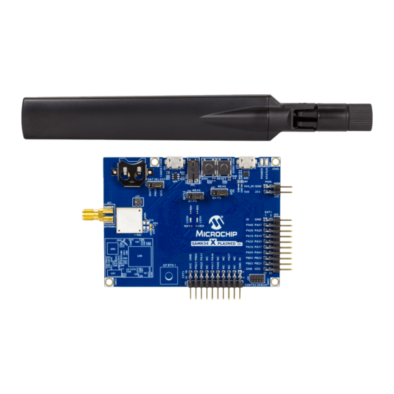
5. Hardware environment setup 5.1. Supported platform and eval board The following board is used/supported in this release. SAMR34 Xplained Pro Part# DM320111 This board can be powered from the Debug USB port located at the top right of the image shown above or by way of the 5v Power Header shown at the top right-hand edge of the above image. -
Page 7: Lorawan Usb_Cdc Example Project
6. LoRaWAN USB_CDC example project The USB_CDC example application code focuses on the elements required to use the on board USB peripheral as a communications console for a Lorawan end node. The following features of the SAMR34 LoRaWAN solution are demonstrated: •... - Page 8 Once you have started the second Tera Term terminal and configured it for the proper baud rate and enabled CRLF line terminations, you can then press the SW0 button on the SAMR34 XPRO board. You will then see a screen similar to the one shown below in the terminal window connected to the TARGET USB connector.
- Page 9 Following the display of the above screen, a join request is sent using the displayed parameters/attributes If the Join operation is not successful, you will be shown a screen similar to the one shown below In this case, a join attempt on Channel 13 (North America band ) has failed. A delay is performed before the next Join attempt.
-
Page 10: Changing Data Rate / Spreading Factor
6.1 Changing Data Rate / Spreading factor It is possible to adjust the Data Rate/spreading factor by way of the SW0 pushbutton, on the SAMR34 XPRO evaluation board. Changing of the Data Rate can be performed by a long press of the SW0 pushbutton. Press and hold the pushbutton until you see the green led turn on. -
Page 11: Changing Tx Power Index
Region DataRate Spreading factor Bandwidth bit/s LED blink count Europe 868 SF12 125Khz SF11 125Khz SF10 125Khz 125Khz 1760 125Khz 3125 125Khz 5470 NOTE: Only 125Khz channels are used in this application Changing TX power index The initial Tx power index setting is set to the maximum TX output power allowed for the region selected. For North America this would be a Tx power Index of 5. -
Page 12: Restoring To Default (Initial) Data Rate And Tx Power Levels
Region Tx Power Index Tx Power dBm LED blink count [30-(2*PwrIndex)] North America Note! Tx power dBm is related to output pins of SAMR34 and does not include any loss in output matching or interface circuitry. Region Tx Power Index Tx Power dBm LED blink count Europe 868... -
Page 13: Manual Pushbutton Sensor Transmission
6.4 Manual PushButton sensor transmission Although the application will periodically transmit a frame containing temperature sensor data, there are times when one would want to manually initiate a sensor transmission by pressing the SW0 pushbutton. A short press of the pushbutton will initiate a sensor transmission using the confirmed message format. Upon short pressing the button, the green led will start blinking, and it will remain blinking until the transaction has completed successfully or fails. -
Page 14: Restarting / Restoring Configuration Upon Power Cycle/Reset
Restarting / Restoring configuration upon power cycle/reset The initial selecting of Region is only necessary during the initial setup. Once the application has be run once, the required parameters and attributes are stored in non volatile memory ( persistent storage ) Upon a power cycle or reset of the device, a check is made to determine if there is previously stored information that can be used to restore operation to settings that were in use before the reset or power cycle.
Need help?
Do you have a question about the SAMR34J18B and is the answer not in the manual?
Questions and answers