Table of Contents
Advertisement
Quick Links
SAMR34 Getting Started LoRaWAN OLED1 [ Button] Quick Start Guide
Introduction
This document is intended as a guide to help you understand the features, and to describe how to use the example
project: SAMR34 Getting Started LoRaWAN OLED1 [ Button ]
Table of Contents
Contents
SAMR34 Getting Started LoRaWAN OLED1 [ Button] Quick Start Guide .................................................. 1
Table of Contents .................................................................................................................................. 1
1.
Overview .................................................................................................................................... 2
1.1
Supported hardware platforms and IDEs ................................................................................... 3
2.
Development environment ......................................................................................................... 4
2.1.
Atmel Studio 7 ........................................................................................................................... 4
2.2.
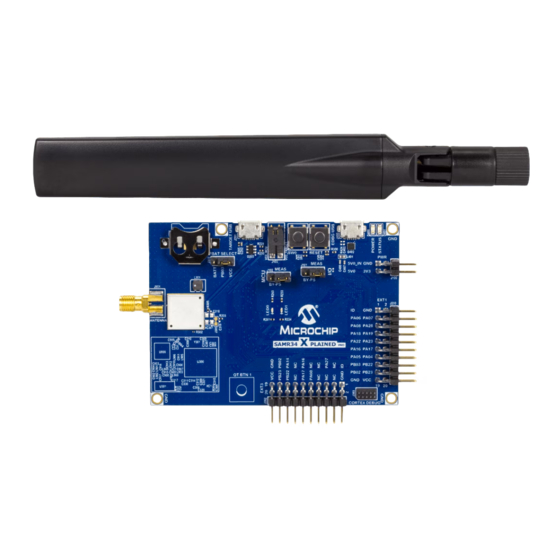
SAMR34 Xplained Pro [DM320111] ......................................................................................... 4
2.3.
OLED1 XPRO extension [ATOLED1-XPRO] ............................................................................ 5
3.
Stack Configurations .................................................................................................................. 6
4.
Building applications in Atmel Studio ......................................................................................... 7
4.1.
Setting Project / Properties ........................................................................................................ 7
5.
Hardware environment setup ..................................................................................................... 8
5.1.
Supported platform and eval board............................................................................................ 8
6.
LoRaWAN OLED1 [Button] example project ............................................................................. 9
6.1
Changing Data Rate / Spreading factor in the field .................................................................. 13
6.2
Changing TX power index ....................................................................................................... 14
6.3
Restoring to default (initial) Data Rate and TX power levels .................................................... 15
6.4
Manual PushButton sensor transmission ................................................................................. 16
6.5
Restarting / Restoring configuration upon power cycle/reset ................................................... 17
1
Advertisement
Table of Contents

Related Manuals for Microchip Technology SAMR34


Summary of Contents for Microchip Technology SAMR34
-
Page 1: Table Of Contents
SAMR34 Getting Started LoRaWAN OLED1 [ Button ] Table of Contents Contents SAMR34 Getting Started LoRaWAN OLED1 [ Button] Quick Start Guide ..........1 Table of Contents ..........................1 Overview ............................ 2 Supported hardware platforms and IDEs ................... 3 Development environment ...................... -
Page 2: Overview
Use pushbuttons on the OLED1 extension to make OLED menu selections NOTE! The OLED1 extension is plugged into the EXT1 header on the SAMR34 XPRO board, and it is important to know that there are some conflicts, and overlapping connections between the SAMR34 XPRO and the OLED1 board on EXT1. -
Page 3: Supported Hardware Platforms And Ides
1.1 Supported hardware platforms and IDEs Supported IDE’s Microcontroller Supported Evaluation Kit SAMR34J18B(SIP) SAMR34 Xplained PRO [ DM320111] Atmel Studio 7 OLED1 Xplained PRO [ATOLED1-XPRO]... -
Page 4: Development Environment
Here are additional links to detailed documents to help you understand the SAMR34/35 LoRaWAN stack http://ww1.microchip.com/downloads/en/DeviceDoc/SAM-R34-R35-Microchip-LoRaWAN-Stack- Software-API-Reference-Manual-DS70005382A.pdf http://ww1.microchip.com/downloads/en/DeviceDoc/SAM-R34-MLS-Getting-Started-Guide-User-Guide- DS50002812A.pdf 2.2. SAMR34 Xplained Pro [DM320111] Full information regarding the SAMR34 Xplained Pro evaluation kit can be found at the links provided: https://www.microchip.com/DevelopmentTools/ProductDetails/DM320111 https://www.microchip.com/wwwproducts/en/ATSAMR34J18 http://ww1.microchip.com/downloads/en/DeviceDoc/ATSAMR34-Xplained-Pro-User-Guide-DS50002803A.pdf... -
Page 5: Oled1 Xpro Extension [Atoled1-Xpro]
2.3. OLED1 XPRO extension [ATOLED1-XPRO] Full information for the ATOLED1-XPRO can be found at the following link: https://www.microchip.com/developmenttools/ProductDetails/ATOLED1-XPRO... -
Page 6: Stack Configurations
By default, the example uses OTAA Join and Unconfirmed periodic transmissions at an interval of 30 seconds. Each SAMR34 XPRO board comes pre programmed with a unique device EUI. If during your development cycle you would like to use your own Device EUI, you can accomplish this by modifying a project setting as described below. -
Page 7: Building Applications In Atmel Studio
4. Building applications in Atmel Studio Atmel Studio 7 is used to develop and build SAMR34 applications. To configure or review the project settings before building your project, follow the instructions below. 4.1. Setting Project / Properties Project settings and properties can be configured thru the Project/Properties menu Tabs To select which device EUI you will be using, select the Toolchain item under project properties. -
Page 8: Hardware Environment Setup
Note! The small battery located at the top left is only for battery backup of the battery backup memory section and is NOT used to actually power the board or SAMR34 device. This battery is not required for this example... -
Page 9: Lorawan Oled1 [Button] Example Project
3. Later we can power the board from a 5v battery pack connected to the the 5v pwr header of the SAMR34 XPRO board, for mobile field measurements. Or use a USB rechargeable 5v battery pack connected to the EDBG Debug connector. - Page 10 This button mapping screen shows you the functions of the OLED1 buttons during menu operations. Use the down button to move the menu selection down, the up button to move menu selection up, and the center select button to make a menu choice. At this point, if you have the cosole connected ,you will see a screen as shown below and to the left.
- Page 11 Having selected the region of operation, the parameters that will be used for joining the network will be displayed. The console will show the screen on the left, and the OLED display will show something similar to that on the right. The OLED will show the DevEUI on line3 and the APPEUI on line 4 The DevEUI is read from the preprogrammed NVM (non volatile memory) of the XPRO board.
- Page 12 The first transmission occurred on channel 11 and the second on channel 14 The TX power index of 05 represents the highest SAMR34 TX power level available for North America. DR0 represents SF10BW125 for North America, and is the lowest data rate available in North America. This is also the configuration that will provide the highest link budget ( highest TX power and best RX sensitivity ) to achieve the longest range .
-
Page 13: Changing Data Rate / Spreading Factor In The Field
When not connected to a serial console, it is still possible to adjust the Data Rate/spreading factor by way of the SW0 pushbutton, on the SAMR34 XPRO evaluation board. Changing of the Data Rate can be performed by a long press of the SW0 pushbutton. -
Page 14: Changing Tx Power Index
The initial Tx power index setting is set to the maximum TX output power allowed for the region selected. For North America this would be a Tx power Index of 5. The SW0 user button on the SAMR34 XPRO can be used to modify this parameter while making field range measurements. -
Page 15: Restoring To Default (Initial) Data Rate And Tx Power Levels
+4 max -12 +2 max -14 Note! Tx power in dBm is related to output pins of SAMR34 and does not include any loss in output matching or interface circuitry. 6.3 Restoring to default (initial) Data Rate and TX power levels... -
Page 16: Manual Pushbutton Sensor Transmission
6.4 Manual PushButton sensor transmission Although the application will periodically transmit a frame containing temperature sensor data, there are times when one would want to manually initiate a sensor transmission by pressing the SW0 pushbutton. A short press of the pushbutton will initiate a sensor transmission using the confirmed message format. Upon short pressing the button, the green led will start blinking, and it will remain blinking until the transaction has completed successfully or fails. -
Page 17: Restarting / Restoring Configuration Upon Power Cycle/Reset
Restarting / Restoring configuration upon power cycle/reset The initial selecting of Region is only necessary during the initial setup. Once the application has been run once, the required parameters and attributes are stored in non volatile memory ( persistent storage ) Upon a power cycle or reset of the device, a check is made to determine if there is previously stored information that can be used to restore operation to settings that were in use before the reset or power cycle.
Need help?
Do you have a question about the SAMR34 and is the answer not in the manual?
Questions and answers