Table of Contents
Advertisement
Quick Links
Advertisement
Table of Contents

Subscribe to Our Youtube Channel
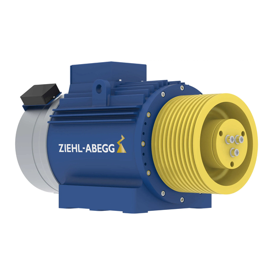
Summary of Contents for ZIEHL-ABEGG ZAtop SM250.80D
-
Page 2: Table Of Contents
Assembly instructions – model series ZAtop Content General information ............Structure of the assembly instructions . -
Page 3: General Information
Exclusion of liability ZIEHL-ABEGG SE is not liable for damage due to misuse, incorrect use, improper use or as a consequence of unauthorized repairs or modifications. -
Page 4: Requirements Placed On The Personnel / Due Diligence
Assembly instructions – model series ZAtop Safety precautions Requirements placed on the personnel / due diligence Danger! " " Installation, connection to the power supply and commissioning may only be performed by qualified service personnel! The relevant regulations must be observed! "... -
Page 5: Versions Of The Brake
Assembly instructions – model series ZAtop Versions of the brake 4 Versions of the brake Figure 4-01 Figure 4-02 - Brake with a mechanical hand release system A brake with a mechanical hand release system is available optionally. The hand release system cannot be fitted later. -
Page 6: Tools Required
The assembly kit brake (article number 70029992), including pos. 5 and pos. 18 to pos. 23 is option- ally available and supplied in a separate folding box. 6 Tools required General • ZIEHL-ABEGG toolkit article 70027450 • Wire cutter • Cable stripper •... -
Page 7: Dismounting The Brake
Assembly instructions – model series ZAtop Dismounting the brake 7 Dismounting the brake During the mounting as well as the dismounting also the operating manual of the brake has to be observed. Risk of death! When dismounting the brake make sure that the cabin and the counterweight are mechanically secured against movement! Caution! "... - Page 8 30 wrench 13. Replace the two hexagon head screws M20 x 300 (11) with threaded bolts M20 (12) from the ZIEHL-ABEGG tool kit, item 70027450. 14. Fasten the two threaded bolts M20 (12) hand tight. 15. Completely unscrew the two remaining hexagon head screws M20 x 300 (11) gradually in turn diagonally with a size 30 wrench.
- Page 9 Assembly instructions – model series ZAtop Dismounting the brake Figure 7-11 Figure 7-12 19. Detach the brake rotor 2 (14) from the toothed hub. The brake rotor may only be detached by hand. ATTENTION! Do not use screwdrivers to release the brake rotor. The screwdrivers damage the friction lining.
-
Page 10: Mounting The Brake
Assembly instructions – model series ZAtop Mounting the brake 8 Mounting the brake During the mounting as well as the dismounting also the operating manual of the brake has to be observed. Risk of death! Incorrect mounting can have a detrimental impact on the braking action. Caution! "... - Page 11 Assembly instructions – model series ZAtop Mounting the brake Figure 8-05 Figure 8-06 7. Slide the brake body 1 (16) slightly over the threaded bolt ATTENTION! Weight of brake body approx. 100 kg! 8. Unscrew12the lifting eye bolt (A). 9. Slide on the brake body 1 (16) as far as the bearing bracket. 10.
- Page 12 Assembly instructions – model series ZAtop Mounting the brake Figure 8-09 Figure 8-10 19. On design with lever for hand release only: Slide the 2 tension blocks (16A) for brake body 2 (13) onto the 2 hexagon head screws for the lever for hand release with the projection towards the outer diameter of the brake.
- Page 13 Assembly instructions – model series ZAtop Mounting the brake 30. Evenly tighten the 4 hexagon head screws M20 x 300 (11) crosswise with a size 30 torque wrench. Tightening torque: 410 Nm 31. Endue the hexagon head bolts with anti tamper paint. 32.
- Page 14 Assembly instructions – model series ZAtop Mounting the brake Figure 8-19 Figure 8-20 Brake wiring diagram with micro switch Brake wiring diagram with inductive proximity switch Figure 8-21 1 Brake release monitoring Figure 8-22 2 Brake 1 Brake release monitoring 3 Shown with currentless brake 2 Brake 3 Minimum strength 2 mA DC...
-
Page 15: Functional Test On Microswitch/Inductive Proximity Switch For Release Monitor
Assembly instructions – model series ZAtop Functional test on microswitch/inductive proximity switch for release monitor 9 Functional test on microswitch/inductive proximity switch for re- lease monitor After mounting of the brake, a functional test must be performed on the micro switches/inductive proximity switches (see chapter "Brake operating instructions - release monitor"... - Page 16 Customer Service phone +49 7940 16-308 +49 7940 16-249 drives-service@ziehl-abegg.com Headquarters ZIEHL-ABEGG SE Heinz-Ziehl-Straße · 74653 Künzelsau Germany phone +49 7940 16-0 · fax +49 7940 16-249 drives@ziehl-abegg.de · www.ziehl-abegg.com...


Need help?
Do you have a question about the ZAtop SM250.80D and is the answer not in the manual?
Questions and answers