
Related Manuals for ZIEHL-ABEGG ZA top SM160.40B/S


Summary of Contents for ZIEHL-ABEGG ZA top SM160.40B/S
- Page 1 Z Z A SM160.30B/S SM160.40B SM160.40B/S Original operating instructions EU-BD 845...
-
Page 2: Table Of Contents
Original operating instructions ZAtop – model series SM160.30B/40B Content General information ............Application . - Page 3 Original operating instructions ZAtop – model series SM160.30B/40B Spare parts ............8.3.1 Replacement of the absolute encoder ECN1313/ERN1387 .
-
Page 4: General Information
The operating instructions address persons entrusted with planning, installation, commissioning and maintenance and servicing and who have the corresponding qualifications and skills for their job. Exclusion of liability ZIEHL-ABEGG SE is not liable for damage due to misuse, improper use or as a consequence of unauthorized repairs or modifications. Copyright The copyright to this operation instructions is held by ZIEHL-ABEGG SE, Künzelsau. -
Page 5: General Safety Instructions
ZAtop – model series SM160.30B/40B Safety instructions Danger! Danger by dangerous, electric voltage! Death or severe injury can occur if the corresponding precautions are not taken! Information Important additional information and advice for user. Warning! Danger by hot surface! Slight bodily harm is possible if the corresponding precautions are not taken! General safety instructions Danger! When the motor shaft is turning, voltage will be induced and applied to the connection terminals! -
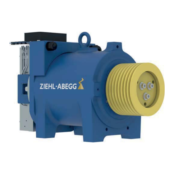
Page 6: Product Overview
first time build a new dimension of machine roomless elevators. Transport " ZIEHL-ABEGG SE electric motors are packed by the manufacturer for the types of transport and storage agreed upon. " Transport the motor(s) either with the original packing or at the casted eyelets or eyebolts using adequate hoists. -
Page 7: Patent Situation
Brake fixation in accordance with the brake operating instructions. Information An exchange of the brake can be carried out only with special centering tool. Please contact the ZIEHL-ABEGG SE customer service in case of a brake exchange! Part.-No. 01008166-GB (EU-BD 845) 7/68... -
Page 8: Fastening Rope Protection Clamp
The adherence to the EMC Directive 2004/108/EC only pertains to this product if controllers tested and recommended by ZIEHL-ABEGG SE are used, which have been installed in accordance with the corresponding controller description and in line with the EMC. If the product is integrated unprofes- sionally into a system or complemented by and operated with components (e. -
Page 9: Absolute Encoder Connection
" The absolute encoder must not be detached mechanically in order not to lose the factory settings. If the absolute encoder has been detached, the new encoder-offset has to be determined with the frequency inverter. Please see the inverter operation instructions for this procedure. Contacts SV120 round connector at absolute encoder ECN1313 (ZIEHL-ABEGG SE standard) Signal Description... -
Page 10: Brake Connection
ZAtop – model series SM160.30B/40B Electrical installation Brake connection " Please also refer to the operating instructions of the brake. SM160.30B Brake type ROBA-twinstop (RTW), Size 250, 2 x 225 Nm SM160.40B Brake type ROBA-twinstop (RTW), Size 350, 2 x 300 Nm "... -
Page 11: Triggering Of The Brakes
" Reduced cooling when installed 1000 m above sea level. Therefore, the torque by 1 % per 100 m must be reduced or the duty cycle time of 1.5 % per 100 m. " Please contact ZIEHL-ABEGG SE in case of orders deviating from the corresponding application conditions. -
Page 12: Drive Approval Test
As an example take a look at simplified diagram. The diagram is to be understood analogously. Their adaptation to other applications must be investigated. ZIEHL-ABEGG does not guarantee their suitability in such circumstances. If the circuitry is made corresponding simplified diagram: Press one of the key buttons at nominal speed until the elevator stops. -
Page 13: Pull Out Of Safety Gear
Start-up ZAtop – model series SM160.30B/40B Simplified diagram for brake activation 1 Voltage supply 2 Button two circuit test 3 / 4 “Open brake” button Pull out of safety gear If the car loaded with the nominal load enters the trap due to a malfunction or during the TÜV certification, it is possible that the trap device is seated rather firmly. -
Page 14: Emergency Evacuation
Start-up ZAtop – model series SM160.30B/40B Emergency evacuation Attention! The measures for emergency evacuation described below may only be performed by instructed persons for maintenance of the lift or qualified personnel of lift companies. 6.5.1 Manual emergency evacuation In case of power failure or failure of the recovery control, emergency rescue is only possible by releasing the brakes manually. -
Page 15: Faults And Remedy
Brake control wrong / defective Check brake wiring Brake coil defective Replace brake (Special tools necessary! Contact ZIEHL-ABEGG SE customer serv- ice) Brake worn out Replace brake rotors (Special tools neces- sary! Contact ZIEHL-ABEGG SE customer service) -
Page 16: Inspection Intervals
Maximum admissible air gap after wear: 0.9 mm! Spare parts Spare parts and accessories not supplied by ZIEHL-ABEGG SE have not been tested or approved by us. These parts may be lower in function or quality and therefore can reduce functionality or safety of the installation. -
Page 17: Replacement Of The Absolute Encoder Ecn1313/Ern1387
ZAtop – model series SM160.30B/40B Service and maintenance 8.3.1 Replacement of the absolute encoder ECN1313/ERN1387 The absolute encoder is mounted on the motor drive shaft opposite the power take off side (see arrow). 8.3.1.1 Required tool for the replacement of the absolute encoder: •... -
Page 18: Mounting The Absolute Encoder
ZAtop – model series SM160.30B/40B Service and maintenance 4. Tighten the screw M10 x 25 (4) with the fitting tool until the absolute encoder is loose. Due to the tightening the screw is pressing onto the central fixing screw (3) and pulls the absolute encoder off the drive shaft. -
Page 19: Replacement Of The Brake
ZAtop – model series SM160.30B/40B Service and maintenance 1. The brakes are used to centre the absolute encoder. 2. Attach the absolute encoder to the drive shaft. 3. Provide threadlocker Loctite 243 (5) or similar threadlocker material to the thread of the central fixing screw (3). -
Page 20: Required Tool For The Replacement Of The Brake
fitted later. The complete brake must be replaced to retrofit the hand release system. 8.3.2.1 Required tool for the replacement of the brake: • ZIEHL-ABEGG toolkit article 70027450 • Tool for replacing the absolute encoder (see chapter "Replacement of the absolute encoder") • Wire cutter •... - Page 21 ZAtop – model series SM160.30B/40B Service and maintenance 5. Feed all connecting cables (4) out of the terminal box (5) and the terminal box plate (6). 6. Unscrew adapter shaft (8) from the motor shaft with wrench (9) and screw wrench SW 32 7.
- Page 22 Service and maintenance ZAtop – model series SM160.30B/40B 8. Loosen the four hexagon head screws (11) on the brake always alternately with a turn. SM160.30B - SW 13 SM160.40B - SW 16 9. Take off the brake body (12). ATTENTION! Weight of the brake body: SM160.30B approx.
-
Page 23: Mounting The Brake
ZAtop – model series SM160.30B/40B Service and maintenance 8.3.2.3 Mounting the brake 1. Fasten the cover plate (16) of the micro switch with the hexagon head screw (15) and a screw wrench SW 16 2. Grease the O-ring (example given Vaseline) and place it in the nut (17) of the brake rotor (13). 3. - Page 24 ZAtop – model series SM160.30B/40B Service and maintenance 7. Push the brake body (12) onto the assembly shaft (10). ATTENTION! Weight of the brake body: SM160.30B approx. 22 kg SM160.40B approx. 30 kg 8. Fasten the brake body evenly all round in steps with four hexagon head screws (11) and washers. SM160.30B - SW 13 - torque: 36 Nm SM160.40B - SW 16 - torque: 48 Nm 9.
-
Page 25: Check The Micro Switches For The Release Monitoring
ZAtop – model series SM160.30B/40B Service and maintenance 14. Insert the connecting cables (4) of the solenoids and the release monitoring as shown in the picture in the terminal box area (6) and connection box (5). 15. Connect the magnet coils and the release monitoring according to the wiring diagram(20) in the top cover of the connection box(5). -
Page 26: Adjusting The Micro Switches For The Release Monitoring
Service and maintenance ZAtop – model series SM160.30B/40B 8.3.2.5 Adjusting the micro switches for the release monitoring Required tool for adjusting the micro switches: • Circuit inductor • screw wrench SW 7 • screw wrench SW16 • Feeler gauge 0,12 mm •... -
Page 27: Replacement Of The Traction Sheave
Service and maintenance ZAtop – model series SM160.30B/40B 8.3.3 Replacement of the traction sheave Warning! Due to incorrect mounting the traction sheave can get loose from the drive shaft! Requirements: • Release the traction sheave and put the ropes off the traction sheave. •... -
Page 28: Mounting The Traction Sheave
ZAtop – model series SM160.30B/40B Service and maintenance 3. Turn the front plate (5) to press off. 4. 5 - 8 mm spacer or hexagon nut (6) must be placed between shaft end and front plate (5). 5. Screw front plate (5) to the traction sheave (4) at the outer circle of holes using hex socket screws M10 x 40 (3). -
Page 29: Fastening Bearing Brackets
Enclosure ZAtop – model series SM160.30B/40B 5. Tighten the fixing screws (3) with a torque wrench with an allen screw SW 8 uniformly in two steps: - Tightening torque step 1: 50 Nm - Tightening torque step 2: 68 Nm 6. -
Page 30: Dimension Sheets
Enclosure ZAtop – model series SM160.30B/40B Dimension sheets Part.-No. 01008166-GB (EU-BD 845) 30/68... - Page 31 Enclosure ZAtop – model series SM160.30B/40B Part.-No. 01008166-GB (EU-BD 845) 31/68...
- Page 32 Enclosure ZAtop – model series SM160.30B/40B Part.-No. 01008166-GB (EU-BD 845) 32/68...
- Page 33 Enclosure ZAtop – model series SM160.30B/40B Part.-No. 01008166-GB (EU-BD 845) 33/68...
-
Page 34: Ec Eu Eclaration Of Conformity
Enclosure ZAtop – model series SM160.30B/40B EC/EU declaration of conformity Part.-No. 01008166-GB (EU-BD 845) 34/68... -
Page 36: Operating Instructions Brake
Enclosure ZAtop – model series SM160.30B/40B Operating instructions brake Part.-No. 01008166-GB (EU-BD 845) 35/68... - Page 37 Enclosure ZAtop – model series SM160.30B/40B Part.-No. 01008166-GB (EU-BD 845) 36/68...
- Page 38 Enclosure ZAtop – model series SM160.30B/40B Part.-No. 01008166-GB (EU-BD 845) 37/68...
- Page 39 Enclosure ZAtop – model series SM160.30B/40B Part.-No. 01008166-GB (EU-BD 845) 38/68...
- Page 40 Enclosure ZAtop – model series SM160.30B/40B Part.-No. 01008166-GB (EU-BD 845) 39/68...
- Page 41 Enclosure ZAtop – model series SM160.30B/40B Part.-No. 01008166-GB (EU-BD 845) 40/68...
- Page 42 Enclosure ZAtop – model series SM160.30B/40B Part.-No. 01008166-GB (EU-BD 845) 41/68...
- Page 43 Enclosure ZAtop – model series SM160.30B/40B Part.-No. 01008166-GB (EU-BD 845) 42/68...
- Page 44 Enclosure ZAtop – model series SM160.30B/40B Part.-No. 01008166-GB (EU-BD 845) 43/68...
- Page 45 Enclosure ZAtop – model series SM160.30B/40B Part.-No. 01008166-GB (EU-BD 845) 44/68...
- Page 46 Enclosure ZAtop – model series SM160.30B/40B Part.-No. 01008166-GB (EU-BD 845) 45/68...
- Page 47 ZAtop – model series SM160.30B/40B Enclosure Part.-No. 01008166-GB (EU-BD 845) 46/68...
- Page 48 Enclosure ZAtop – model series SM160.30B/40B Part.-No. 01008166-GB (EU-BD 845) 47/68...
- Page 49 ZAtop – model series SM160.30B/40B Enclosure Part.-No. 01008166-GB (EU-BD 845) 48/68...
- Page 50 ZAtop – model series SM160.30B/40B Enclosure Part.-No. 01008166-GB (EU-BD 845) 49/68...
-
Page 51: Eu Eclaration Of Conformity Of The Brake
ZAtop – model series SM160.30B/40B Enclosure EU declaration of conformity of the brake Part.-No. 01008166-GB (EU-BD 845) 50/68... -
Page 52: Eu Type-Examination Certi Fi Cate
ZAtop – model series SM160.30B/40B Enclosure Part.-No. 01008166-GB (EU-BD 845) 51/68... - Page 53 ZAtop – model series SM160.30B/40B Enclosure EC type-examination certificate Part.-No. 01008166-GB (EU-BD 845) 52/68...
- Page 54 Enclosure ZAtop – model series SM160.30B/40B Part.-No. 01008166-GB (EU-BD 845) 53/68...
- Page 55 ZAtop – model series SM160.30B/40B Enclosure Part.-No. 01008166-GB (EU-BD 845) 54/68...
- Page 56 Enclosure ZAtop – model series SM160.30B/40B Part.-No. 01008166-GB (EU-BD 845) 55/68...
- Page 57 ZAtop – model series SM160.30B/40B Enclosure Part.-No. 01008166-GB (EU-BD 845) 56/68...
- Page 58 ZAtop – model series SM160.30B/40B Enclosure Part.-No. 01008166-GB (EU-BD 845) 57/68...
- Page 59 ZAtop – model series SM160.30B/40B Enclosure Part.-No. 01008166-GB (EU-BD 845) 58/68...
-
Page 60: Calculation Of Tripping Speed
Enclosure ZAtop – model series SM160.30B/40B 9. .1 Calculation of tripping speed = diameter of the traction sheave (table contains typical traction sheave diameters, other diameters can be recalculated linear) = maximum nominal speed of the brake rotor Nbmax = maximum trip torque of the brake rotor = maximum rated speed of the elevator Vmax = maximum tripping speed of the elevator... -
Page 61: Shaft Calculation
ZAtop – model series SM160.30B/40B Enclosure Shaft calculation Part.-No. 01008166-GB (EU-BD 845) 60/68... - Page 62 ZAtop – model series SM160.30B/40B Enclosure Part.-No. 01008166-GB (EU-BD 845) 61/68...
- Page 63 ZAtop – model series SM160.30B/40B Enclosure Part.-No. 01008166-GB (EU-BD 845) 62/68...
- Page 64 ZAtop – model series SM160.30B/40B Enclosure Part.-No. 01008166-GB (EU-BD 845) 63/68...
- Page 65 ZAtop – model series SM160.30B/40B Enclosure Part.-No. 01008166-GB (EU-BD 845) 64/68...
- Page 66 Enclosure ZAtop – model series SM160.30B/40B Part.-No. 01008166-GB (EU-BD 845) 65/68...
- Page 67 ZAtop – model series SM160.30B/40B Enclosure Part.-No. 01008166-GB (EU-BD 845) 66/68...
- Page 68 ZAtop – model series SM160.30B/40B Enclosure Part.-No. 01008166-GB (EU-BD 845) 67/68...
- Page 72 Customer Service phone +49 7940 16-308 +49 7940 16-249 drives-service@ziehl-abegg.com Headquarters ZIEHL-ABEGG SE Heinz-Ziehl-Straße · 74653 Künzelsau Germany phone +49 7940 16-0 · fax +49 7940 16-249 drives@ziehl-abegg.de · www.ziehl-abegg.com...
Need help?
Do you have a question about the ZA top SM160.40B/S and is the answer not in the manual?
Questions and answers