ZIEHL-ABEGG ECblue Assembly Instructions Manual
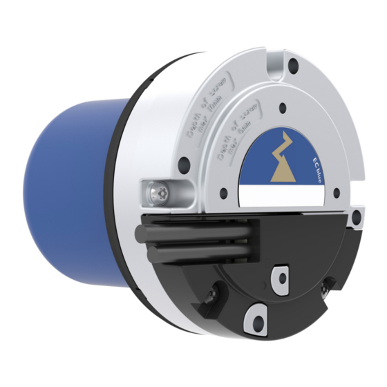
Electronically commutated motors for the drive of fans. motor sizes: z (mk055), o (mk072)
Hide thumbs
Also See for ECblue:
- Assembly instructions manual (59 pages) ,
- Operating instructions manual (10 pages) ,
- Quick start manual (32 pages)

Related Manuals for ZIEHL-ABEGG ECblue


Summary of Contents for ZIEHL-ABEGG ECblue
- Page 1 ECblue Motor sizes: Z (MK055), O (MK072) Electronically commutated motors for the drive of fans Assembly instructions Keep for reference! L-BAL-F063-GB 2022 Index 007 Part.-No. 00702474-GB...
-
Page 2: Table Of Contents
Assembly instructions ECblue Content General notes ............. - Page 3 Assembly instructions ECblue Start-up ..............
-
Page 4: General Notes
We do not accept any liability for possible errors or omissions in the information contained in data, illustrations or drawings provided. ZIEHL-ABEGG SE is not liable for damage due to misuse, improper use or as a consequence of unauthorized repairs or modifications. -
Page 5: Safety Instructions
Assembly instructions ECblue Safety instructions 2 Safety instructions Intended use Attention! • The motors are intended for powering fan impellers, tools, belts, rollers, gearboxes etc. • The motor is to be used exclusively as a built-in component. The connecting cable (power supply connection) should therefore be viewed as an internal cable. -
Page 6: Product Safety
Assembly instructions ECblue Safety instructions Information Important additional information and advice for user. Product safety The device conforms to the state of the art at the time of delivery and is fundamentally considered to be reliable. The device and its accessories must only be used in a flawless condition and installed and operated in compliance with the assembly instructions and/or operating instructions. -
Page 7: Modifications / Interventions In The Device
Use only genuine spare parts / genuine wearing parts / genuine accessories from ZIEHL-ABEGG.Th- ese parts were specifically designed for the device. There is no guarantee that parts from non-original sources are designed and manufactured in correspondence with load and safety requirements. -
Page 8: Functional Description
Assembly instructions ECblue Product overview Functional description ECblue stands for EC fans and motors with maximum efficiency. Highly efficient, electronically commutated motors with permanent magnets are used the speed of which is controlled by the integrated controller. The devices are constructed in accordance with the general requirement in EN 61800-2 for adjustable speed electrical power systems and is intended for one-quadrant drives. -
Page 9: Transport, Storage
• The max. permissible mass of the impeller ort he component to be driven must be inquired from and confirmed in writing by ZIEHL-ABEGG. • Motors are not balanced as standard, a complete balancing with mounted fan impeller or the component to be driven is necessary. -
Page 10: Dimensions [Mm]
Assembly instructions ECblue Mounting Dimensions [mm] Design P for driving pressed-on fan impellers MK055 version A (stator diameter 101 mm) MK055 version B (stator diameter 89 mm) MK072 (stator diameter 101 mm) L-BAL-F063-GB 2022 Index 007 Part.-No. 00702474-GB 10/27... - Page 11 Assembly instructions ECblue Mounting Design N for driving non pressed-on fan impellers or other components MK055 version A (stator diameter 101 mm) MK055 version B (stator diameter 89 mm) MK072 (stator diameter 101 mm) Tightening torques M Thread size Property class 8.8, friction coefcient µges = 0.12...
-
Page 12: Connection Lead & Terminal Box
Assembly instructions ECblue Mounting Connection lead & terminal box Information In demanding environments (wet areas, open air installation) all connections must incorporate water drainage curves. To ensure that water cannot penetrate through to the controller housing from the connections install a terminal box lower than the motor. -
Page 13: Electrical Installation
Assembly instructions ECblue Electrical installation 5 Electrical installation Safety precautions Danger due to electric current • Work on electric components may only be carried out by trained electricians or by persons instructed in electricity under the supervision of an electrician in accordance with electrical engineering regulations. -
Page 14: Required Quality Attributes For The Mains Voltage
Assembly instructions ECblue Electrical installation 5.3.2 Required quality attributes for the mains voltage Danger due to electric current The mains voltage must comply with the EN 50160 quality characteristics and the defined standard voltages in IEC 60038! 5.3.3 Operating in IT-System Danger due to electric current •... - Page 15 Assembly instructions ECblue Electrical installation Version with connection cables Cable banderole Connection Diagram Lead Color on field side according to local / national 0-10V / requirments OC Out e.g. NEC / NFPA GN or GNYE GNYE WH or GR BU or RD The bands around the cables show national colour codes which may be available on the field side.
-
Page 16: Analog Input "E1" For Setting Speed
Assembly instructions ECblue Electrical installation 5.6.2 Analog input “E1” for setting speed The device has an analog input for setting the motor speed. Connection “E1” / “GND” (R see Technical data). Danger due to electric current • Ensure correct polarity! •... -
Page 17: Specification Signal/Speed Characteristic Curve
Assembly instructions ECblue Electrical installation 5.6.3 Specification signal/speed characteristic curve In “Constant speed” mode, the motor speed is proportional to the specification signal. This is an example - other operating modes/characteristic curves are possible by agreement. Characteristic curve: Motor speed proportional to specification signal... -
Page 18: Potential At Control Voltage Connections
Assembly instructions ECblue Electrical installation 5.6.6 Potential at control voltage connections The control voltage connections (< 50 V) relate to the joint GND potential (Exception: Relay contacts are potential free). There is a potential separation between the control voltage connections and the protective earth. -
Page 19: Selecting The 3 Speeds
Assembly instructions ECblue Start-up 5.7.2 Selecting the 3 speeds Speed 3 N - C bridged = Speed step 3 ECblue L1 - C bridged = Speed step 2 Speed 2 ECblue C not connected = Speed setting 1 Speed 1... -
Page 20: Diagnostics / Faults
Assembly instructions ECblue Diagnostics / Faults 7 Diagnostics / Faults Status message via LED flashing code LED Code Cause Reaction of Controller Explanation Adjustment Line voltage available? Unit switch OFF and automatically ON when the voltage No line voltage has been restored... - Page 21 Assembly instructions ECblue Diagnostics / Faults LED Code Cause Reaction of Controller Explanation Adjustment Cooling down period power module Power module cooling down period for approx. 60 sec. Cooling down period power module for approx. 60 sec. Final shutoff after 2 cooling-off intervals see code 6.
-
Page 22: Service Work
Assembly instructions ECblue Service work 8 Service work Repairs / maintenance Attention! • Observe the safety information! • No maintenance work at running motor! • Any faults detected in the electric system/modules/operating equipment must be corrected immediately. If these faults are not corrected, the device/system is potentially very dangerous. The device/system must therefore not be operated when it is faulty. -
Page 23: Enclosure
Assembly instructions ECblue Enclosure 9 Enclosure Technical data Line voltage* 1 ~ 200...240 V, 50/60 Hz (see rating plate) 1 ~ 100...130 V, 50/60 Hz (Versions for DC power supply on request) Maximal line fuse 10 A Line protection switch with charakteristik B (Recommendation: max. - Page 24 Assembly instructions ECblue Enclosure Harmonics current According to EN 61000-3-2 (see Electrical installation / EMC-compatible installation / Harmonics current). Max. leakage current according to the < 3.5 mA defined networks of EN 60990 dB(A) values see product catalog Protection class of motor according to...
-
Page 25: Connection Diagram
Assembly instructions ECblue Enclosure Connection diagram Version with 0...10 V input ECblue (MK055/072-_I_._ _._ _) (_ _ _ _ _-_I_.Z_._ _ _ _) (Q_ _ _ _-_ _ _ ._ _.B_) 10V GND A1 10 k Netzspannung Leistungsschild Line voltage... - Page 26 Assembly instructions ECblue Enclosure Version with three speeds ECblue (3 speeds) (MK055/072-_I_._ _._ _) (_ _ _ _ _-_I_.Z_._ _ _ _) (Q_ _ _ _-_ _ _ ._ _.B_) Drehzahl 1 Speed 1 Drehzahl 2 Speed 2 Drehzahl 3...
-
Page 27: Manufacturer Reference
Assembly instructions ECblue Enclosure Manufacturer reference Our products are manufactured in accordance with the relevant international regulations. If you have any questions concerning the use of our products or plan special uses, please contact: ZIEHL-ABEGG SE Heinz-Ziehl-Straße 74653 Künzelsau phone: +49 (0) 7940 16-0 info@ziehl-abegg.de...
Need help?
Do you have a question about the ECblue and is the answer not in the manual?
Questions and answers