Table of Contents
Advertisement
Advertisement
Table of Contents

Related Manuals for SAJ AS1-3KS-5.1


Summary of Contents for SAJ AS1-3KS-5.1
- Page 1 - 1 -...
- Page 2 Content CONTENT ........... - 1 - CHAPTER 1 SAFETY PRECAUTIONS ....- 4 - ..........- 4 - 1.1 S AFETY ........- 7 - 1.2 S YMBOLS INSTRUCTIONS ........- 8 - 1.3 E MERGENCY SITUATION CHAPTER 2 PRODUCT INTRODUCTION ....- 12 - ........
- Page 3 CHAPTER 4 ELECTRICAL CONNECTIONS ..... - 32 - ....... - 32 - 4.1 E LECTRICAL NTERFACE ESCRIPTION ....... - 34 - 4.2 S YSTEM IRING CHEMATIC ..........- 35 - 4.3 AS1 W IRING ..........- 38 - 4.4 B1 W IRING ....
- Page 4 WARRANTY CARD ........- 78 - - 3 -...
- Page 5 Chapter 1 Safety Precautions This user manual describes the instructions and procedures for the installation of the AS1 AC Retrofit Battery System. Please read the user manual before operating it. Keep this user manual properly and operate strictly according to all safety tips and operation instructions in this manual.
- Page 6 •Do not use wet hands to touch the system. •Any behavior to change the functionality of the product without permission will cause fatal injury to the operator, third parties, and equipment. SAJ is - 5 -...
- Page 7 not responsible for these losses and warranty claims. Caution •Do not modify or tamper with AS1 and other components of the system. •Risk of injury by hoisting or falling system •Inverters and batteries are heavy and personal injury can be caused if the inverter or battery is improperly lifted or dropped during transport or improper operation when attached or removed from walls.
- Page 8 1.2 Symbols instructions Symbol Description Dangerous electrical voltage The device is directly connected to public grid, thus all work to the battery shall only be carried out by qualified personnel. No open flames Do not place or install near flammable or explosive t i l Corrosive substance Keep the inverter away from corrosive substance.
- Page 9 This device SHALL NOT be disposed of in residential waste Please go to Chapter 8 “Recycling and Disposal” for proper treatment. CE Mark The device is in compliance with Low Voltage Detective and Electromagnetic Compatibility. Recyclable 1.3 Emergency situation Despite of its careful and professional protection design against any hazard results, damage of the battery may still occur.
- Page 10 thoroughly and seek medical advice. 3)Inhalation: If you feel discomfort, dizziness or vomiting, seek medical advice immediately. 4)Use a FM-200 or Carbon Dioxide (CO2) fire extinguishers to extinguish the fire if there is a fire in the area where the battery pack is installed.
- Page 11 occur due to mechanical damage, internal pressure and etc., and may result in a leakage of battery electrolyte. The electrolyte is corrosive and flammable. When there is fire, the toxic gases produced will cause skin and eyes irritation, and discomfort after inhalation.
- Page 12 lithium metal. If the shell is broken, it will come into direct contact with the air, resulting in combustion. The electrolyte will be ignited at the same time, resulting in strong flame, rapid expansion of gas and explosion. - 11 -...
- Page 13 AS1 can be expanded in capacity according to user demands, and the modular design of the slave device makes it easy to install wiring. The AS1 series includes AS1-3KS-5.1, AS1- 3KS-10.2, AS1-3KS-15.3 and AS1-3KS-20.4 models. In daytime, electricity generated by photovoltaic system will be...
- Page 14 1* AS1+2* B1 AS1-3KS-20.4 20.4kWh 1* AS1 +3* B1 Figure 2.1 Configuration of AS1-3KS-5.1/AS1-3KS-10.2/ AS1-3KS-15.3,/AS1-3KS- 20.4 Note: Please do not connect any other brands of battery packs (except for the B1-5.1-48 battery pack) to the battery ports of AS1 series products.
- Page 15 2.2 System Schematic The schematic of PV system is shown below: Fig. 2.1 System schematic diagram 2.3 Product Model Description AS1 – XKS – XX ② ③ ④ ① AS1 represents the product series. ① XK indicates the rated power of the product XkW, such as 3K ②...
- Page 16 Indicates the built-in battery capacity, such as 5.1 for 5.1kWh. ④ 2.3 Datasheet AS1-3KS-5.1 AS1-3KS-10.2 AS1-3KS-15.3 AS1-3KS-20.4 Type Battery Data Battery Type Lithium ion Total Energy 5120 10240 15360 20480 Capacity[Wh] Battery Capacity [Ah] Rated Voltage [V] 51.2 Voltage Range 42~58.4...
- Page 17 Max. Continuable Output Power 3000 [VA] Max.Output Current 13.1 [A]@230Vac Max.Output Fault Current [A] Inrush Current [A] Max.Output Overcurrent Protection [A] Rated Grid/Backup 220, 230, 240/180-280 Voltage/Range Rated Grid/Backup 50, 60/±5 Frequency/Rang e [Hz] Power factor [cos 0.8 leading~0.8lagging φ] Feed-in L+N+PE - 16 -...
- Page 18 AC Output [Back-up Mode] Max. Continuable Output Power 3000 [VA] Output Voltage 220/230/240 Max.Output Current 13.1 [A]@230Vac Output 50/60 Frequency [Hz] Max.Output 3600 ,10sec Power [VA] General Data Communication Wi-Fi/4G/Ethernet(Optional) Mode Operating Temperature 0°C~50°C (>45℃ derating) Range Cooling Method Natural Convection Ambient Humidity 0-95% Non-condensing Noise[dBA]...
- Page 19 Protection Dimensions 738*650*186 1160*650*186 1580*650*186 2000*650*186 [H*W*D][mm] Weight [kg] Standard Warranty [Year] Applicable AS 4777.2, VDE 4105, G98, C10/C11, CEI0-21, IEC 62619, IEC Standard 62040 - 18 -...
- Page 20 Chapter 3 Installation Instructions 3.1 Packing List of AS1 1* AS1 1* Mounting Bracket 6*Hexagon head wood screw 1* 4G Module 6* Expansion tube 6* Screw washer 2* CT 1* Cross recessed hexagon 6* E6012 tubular insulator 1* User Manual bolts group (M6*12) terminal Table 3.1 Packing List for AS1...
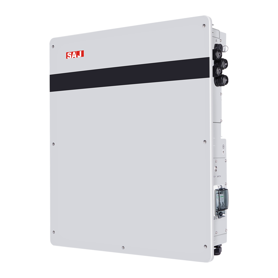
- Page 21 3.2 Determine the Installation Method and Location AS1 series product dimension Fig. 3.1 AS1-3KS-5.1 apparent and dimension diagram AS1-3KS-5.1 is cooled by natural wind convection. It is recommended to install in indoors or sheltered areas to avoid direct sunlight, rain and snow.
- Page 22 Fig. 3.2 Installation location Vertical ground mounting method is recommended and it is allowed to be installed by maximum tilting 15° backward. Do not install it horizontally or upside down. √ √ × × × Fig. 3.3 Installation angle - 21 -...
- Page 23 Please ensure the air circulation is good at the installation area for heat dissipation. Bad air ventilation will affect the working performance of internal electronic components and shorten the service life of AS1. 50CM 50CM 50CM Fig. 3.4 Installation distance The following sites are not allowed for installation: a.
- Page 24 g. sites where the freezing point is reached, like garages, carports or other places; h. sites with humidity and condensation is above 85%; i. places with plenty of salt; j. flooded areas; k. within 600mm of any hot water unit, air conditioning unit o any other appliance associated with the pre-assembled integrated battery energy storage system 3.3 Installation Procedure for AS1...
- Page 25 drive the screw fixing seat into the holes to fix the bracket. Fig. 3.5 Dimensions of Mounting Bracket for AS1 Unit: mm. - 24 -...
- Page 26 ∅ Fig. 3.6 Position of holes on the wall Unit: mm Fix the mounting bracket with hex head screw on the installation positions. Fig. 3.7 Fixing the mounting bracket - 25 -...
- Page 27 Step 3: Please hang the AS1 to the mounting bracket and make sure the device is snugly fits with the bracket. Fig.3.8 Hang the AS1 to the Mounting Bracket 3.4 Installation Procedure for B1 Notice: If any B1 device is connected to the AS1, please install the B1 prior to AS1 installation in case the space is not enough.
- Page 28 Step 1: Pre-check the installation distance of the B1 to other items. Fig.3.9 B1-5.1-48 dimension (Unit: mm) Step 2: Mark the proper positions of mounting bracket and drill holes on those positions (8mm in diameter, 50mm in depth) by using the mounting bracket as a template, and then use a rubber hammer to drive the screw fixing seat into the holes to fix the bracket.
- Page 29 Fig. 3.10 B1-5.1-48 hanging panel dimension ∅ Fig.3.11 B1-5.1-48 Hanging holes position on the wall Unit: mm Note: The recommended installation distances among the AS1 and the B1 mounting brackets can be found in Fig. 3.12. - 28 -...
- Page 30 Primary Secondary 1 Secondary 2 Secondary 3 Fig. 3.12 Distances among mounting brackets Unit: mm Step 3: After the mounting bracket fixed and before hanging the AS1/ B1 on the mounting bracket, please remove the plug from the waterproof nut of the AS1 and B1, then put on the cable gland but not tighten it up yet.
- Page 31 Fig. 3.13 Waterproof rings. Step 4: If there are more than one unit of B1 connected to the AS1, please install B1 No.3 first, B1 No.2 secondly, B1 No.1 thirdly and finally (refer Fig.3.15), from bottom top. Please hang the AS1 & B1 to the mounting bracket with the order as mentioned above and make sure all equipment are attached to the bracket well.
- Page 32 Fig. 3.14 Hang B1 & AS1 together to the mounting brackets - 31 -...
- Page 33 Chapter 4 Electrical Connections 4.1 Electrical Interface Description Fig. 4.1 AS1-3KS-5.1 electrical interfaces - 32 -...
- Page 34 Code Name DRMS Port CT connection RS232 communication Grid connection Backup connection Ground BMS switches Battery switches BAT+ BMS LINK BAT- Table 4.1 Interface description - 33 -...
- Page 35 4.2 System Wiring Schematic Module Grid Back-up Fig. 4.2 Wiring schematic diagram Do not connect the backup loads side with the grid or battery BACKUP BACKUP Fig. 4.3 Wrong connection example - 34 -...
- Page 36 4.3 AS1 Wiring Notice: Please turn off the Battery Switch and DC Switch as well as external AC breaker after unpacking in any cases before and during wiring in case of electric shock. Wiring Methods for AS1: Step 1: Please unscrew the screws and remove the cover plates on right UPPER side of the AS1 for wiring.
- Page 37 Step 2: After the cover plate removed, please lead one cable (Recommend conductor core size: 2.5mm ) through the waterproof nut (GRID) and then use E6012 wire crimps to connect the wires to the terminal of GRIDL, GRIDN and GND2 properly (refer to Fig.4.4); Step 3: Please lead another cable (Recommend conductor core size: 2.5mm ) through the waterproof nut (BACKUP) and then use E6012...
- Page 38 GRID BACKUP Fig.4.4 AS1 device wiring terminals Step 5: Ground Connection Remove the external hex head screw and lead a grounding line through OT terminal, screw it into the grounding port of AS1enclosure (in clockwise direction ) and make sure it is screwed up tightly. - 37 -...
- Page 39 Fig. 4.5 Ground connection 4.4 B1 Wiring Notice: If no B1 device wired to the AS1, please ignore this section). For expanding the system capacity, the B1(s) shall be paralleled to the AS1. Ensure DC switch is off during installation to avoid the risk of - 38 -...
- Page 40 short circuit caused by wrong operation during battery wiring. To parallel B1 to the AS1, please follow the procedures below: Step 1: Please remove battery cover plate of the AS1 device from the lower right area and right side of the B1 unit before wiring. (The cable connected to the Battery Switch inside the cover plate can be plugged out first if needed).
- Page 41 DIP Switch of AS1 DIP Switch of B1 Fig. 4.7 Secondary device wiring terminal Step 3: Lead the RJ45 communication cable (not press the RJ-45 plugs yet) from the fastening head of AS1 to the fastening head of (30kgf.cm (torque) is recommended).
- Page 42 Fig. 4.8 RJ45 pins of LINK Pin Number Description Effect White-orange Orange White-green Blue White-blue Green White-brown Brown Table4.1 LINK pins description - 41 -...
- Page 43 DIP switch configuration can be found below: Secondary Secondary Secondary Configuration (DIP) NO.1 (DIP) (DIP) NO.2 (DIP)NO.3 1*AS1 Only 1*AS1 & 1*B1 1*AS1 & 2*B1 1*AS1 & 3*B1 4.2 DIP switch configuration Table Step 4: Please reconnect Battery Switch cable into (PCBA-CN3) port of PCB of the AS1 and B1 before screw up the plates, then screw up the cover plates back to the AS1 and B1 respectively (14kgf.cm (torque) is recommended.
- Page 44 this section. Do not connect one B1 to two different AS1 devices at the same time. Step 5: Please use a wrench to fasten cable gland of the AS1 and (30kgf.cm (torque) is recommended.) And it is recommended to apply fire resistance paint onto the cable between AS1 and B1 cable glands.
- Page 45 4.5 Communication Interface Description Fig. 4.10 RS232 pins Pin number Name RS-232 TX RS-232 RX Table 4.3 RS232 pins description Note: The RS232 interface can be connected to the eSolar GPRS/4G/WiFi module. For operation details, please refer to the quick installation guide of each monitoring module. - 44 -...
- Page 46 4.6 Inverter Demand Response Mode To comply with Australian and New Zealand safety requirements, the DRMs terminals should be connected. A RJ45 plug is being used as the inverter DRED connection. Fig. 4.11 DRMS pins Mode Corresponding pins Requirement DRM0 5 &...
- Page 47 DRM2 2 & 6 The inverter is consuming less than 50% of rated power DRM3 3 & 6 The inverter is consuming less than 75% of rated power AND source reactive power if capable DRM4 4 & 6 The inverter is consuming 100% of rated power (Subject to constrains from other active DRMs) DRM5...
- Page 48 4.7 CT Installation Different solutions are offered for sampling data from PV and Grid side. The standard solution is CT solution and the optional solution is Meter solutions. Please choose to use one of the solutions to realize the sampling function. Please do not use the CT (standard solution) and meters (optional solution) in a same system, otherwise the system will run abnormally.
- Page 49 (CT/METER) nut on the AS1 and connect the plug to PV_CT port on the PCBA of the AS1; Notice: Both CTs directions shall point to the load side. Please notice the CT direction. Name Name RS485_A RS485_B pins Fig. 4.12 CT/Meter Table.
- Page 50 Fig. 4.13 CT installation - 49 -...
- Page 51 Fig. 4.14 CT connection Diagram 4.7.2 Meter Solution There are two types of smart meters (built-in CTs) available for varied system types. Model Accuracy Class Frequency Reference Voltage Instrument constant DDSU666 Active Class 1 50Hz 230V 800imp/kWh DTSU666 Active Class 1 50Hz 380V 400imp/kWh...
- Page 52 Please choose to use single phase or three phase meters based on the Grid and PV system types. Cannot use single phase and three phase meters at a same time. 4.7.2.1 Three Phase Grid & Three Phase PV System In a three phase grid & three phase PV system, two units of three- phase meters can be used to sample voltage and current at PV side and grid side separately.
- Page 53 Fig. 4.15 Two three-phase meters 4.7.2.2. Single Phase Grid & Single phase PV system In a single phase grid & single phase PV system, one unit of three- phase meter shall be used to sample voltage and current. Phase C of the meter is used to sample voltage and current value of the PV side, while Phase A of the meter is used to sample voltage and current value of the grid side.
- Page 54 The default address for the meter is 1 in this case. Fig.4.16 Wiring diagram for one unit of three phase meter 4.7.2.3. Single Phase Grid& Single Phase PV System In a single phase grid & single phase inverter system, two units of single -phase meters can be used to sample voltage and current at PV side and grid side.
- Page 55 Please install the 1-phase meters with reference diagram as showed in Fig. 4.17. Please set the meter address (Grid side) into 1 and set the meter address (PV side) into 2. Please refers to section 4.8.1 for meters setting methods. Fig.
- Page 56 please ignore this section. 4.8.1 Setting Methods for Single Phase Meter The setting methods for single-phase meter is as follows: once wait Long press once once wait once Fig. 4. 18 Procedure of single phase meter address setting - 55 -...
- Page 57 ① Power on the meter to the display interface and long press button to enter meter swiching interface, select and wait for 2s to enter meter address page automatically. ② After entering the address page, please press to set meter address according to the system type into 1 or 2. ③...
- Page 58 Power on once once once once once Measure display Shift Shift twice once once twice once thrice Password correct, enter the setting interface Fig. 4.19 Procedure of three phase meter address setting ① Power on the meter and enter the “Measure display” interface, then press button twice for entering password 701.
- Page 59 increment per button pressing ⑥ After the address set successfully, press button twice to exit to Measure display interface to get the meter work. Button Description Confirmation or cursor shift (when input digits) Exit → Table 4.3 Button description of three phase meter 4.7 External AC Circuit Breaker and Residual Current Device Please install a circuit breaker to ensure the inverter is able to...
- Page 60 Chapter 5 Debugging Instructions 5.1 Human-computer Interface Introduction 100% 100% Fig. 5.1 Human-computer interface - 59 -...
- Page 61 Description LED lamps state Green lamp flicker Battery discharging from bottom to top Green lamp flicker Battery charging from top to bottom Green/R Red lamp flicker:1 Standby ed LED s/time lamp Green lamp and red lamp flicker in Procedures are being upgrade alternative Red lamp Always light Faults in device...
- Page 62 1) Turn ON the DC switch at the right side of the B1 No.3> B1 No.2>B1 No.1> AS1; 2) Turn on the battery switch at the right side of the B1 No.3> B1 No.2>B1 No.1> AS1; 3) Wait for 30s and observe the LCD and LED indicators on the front of AS1 to check the running status of the.
- Page 63 download and install this APP. 5.4.2 Commission Configuration Step 1: Login to the commission App with user name and account Step 2: Set the grid compliance, time zone as per instructions showed on the App. Step 3: Select the system operation Mode (refer to Appendix I) Step 4: Installer shall create account for End user (refer to 4G/Wi- Fi Module user manual) Step 5: Checking the system operation status...
- Page 64 5.5 Shut Down the Inverter Notice: If the AS1 is connected with B1(s), the procedure for turning off the system will be B1 No.3>> B1 No.2>> B1 No.1>> AS1 (refer to Fig. 3.12) System shall be turned OFF in the correct sequence as follows: Turn OFF the DC switch on the right side of the AS1/B1 2) Press (approx.
- Page 65 Chapter 6 Fault Codes and Common Troubleshooting Explanation Fault type Communication loss of the main and Error subordinate machine Master High temperature Master Error Low temperature Master Error DCI Err Master Error Synchronizing pulse fault Master Error Relay fault Master Error Storage fault Master Error...
- Page 66 Master Battery discharging fault Master Error Battery controller overcurrent Master Error Bus soft-start timeout Master Error Bus voltage high Master Error Bus voltage low Master Error Bus voltage high of hardware Master Error Inverter overcurrent Master Error Inverter hardware overcurrent Master Error Inverter short circuit fault Master Error...
- Page 67 Grid average overvoltage within 10 Alarm mins Master Overload alarm Master Alarm Fan Err Slave Error Output terminal abnormal Slave Error Inverter voltage wave form fault Error Slave Grid voltage consistent alarm Slave Alarm Grid frequency consistent alarm Alarm Slave GND Loss Warn Alarm LN Wrong Warn...
- Page 68 Voltage of grid high warning Slave Alarm Voltage of grid low warning Slave Alarm Grid over frequency alarm Slave Alarm Grid under-frequency alarm Slave Alarm Grid loss alarm warning Slave Alarm Communication loss of the main and Error subordinate machine Slave Storage fault Slave Error RTC fault Slave...
- Page 69 Over charging temperature alarm Slave Alarm Battery low voltage alarm Slave Alarm BMS communication loss alarm Slave Alarm Ammeter communication loss alarm Alarm Slave DRM0 alarm Slave Alarm - 68 -...
- Page 70 Chapter 7 Inverter & battery maintenance 7.1 Transportation Lithium batteries are dangerous goods. Passed the test of UN38.3, this product meets the transportation requirements for dangerous goods for lithium batteries. After the installation of the battery on site, the original packaging (contains the lithium battery identification) should be kept.
- Page 71 The battery cannot be disposed of as household refuse. When the service life of the battery reaches to the limit, it is not required to return it to the dealer or SAJ, but it must be recycled to the special waste lithium battery recycling station in the area 7.3 Cleanliness...
- Page 72 agents as it may damage the components. - 71 -...
- Page 73 Appendix I: Brief Introduction about the system operation modes: Self-consumption Mode The power generated by the energy storage system will mainly be used to support the load, and surplus power will be adopted for battery charging and once the battery is full, the more surplus energy will be fed into the grid.
- Page 74 do not need to change the electricity consumption habits of users. Revenue from TOU price management is mainly obtained through price difference and adjustment of electricity utilization plan. Operating with this mode, users can arrange the electricity utilization plan according to their actual situation, and transfer the electricity demand from the period with higher electricity price to the period with lower electricity price to achieve the purpose of reducing the overall electricity price level.
- Page 75 Appendix II: Setting Reactive Power Control Setup Fixed Power Factor mode The characteristic power factor curve for cosφ (P) (Power response) mode varies the displacement power factor of the output of the inverter in response to changes in the output power of the inverter. The response curve required for the cosφ...
- Page 76 Curve for a Volt-Var control Curve for a Volt-Watt response mode (AS4777 Series) mode (AS4777 Series) - 75 -...
- Page 77 Chapter 8 Contact Us Guangzhou Sanjing Electric Co., Ltd. Headquarter: SAJ Innovation Park, No.9, Lizhishan Road, Science City, Guangzhou High-tech Zone, Guangdong, P.R.China. Jiangxi Factory: Building D10, D11, Ganzhou International Port Electronic Info Industrial Park, Longling Town, Nankang District, Cangzhou City, Jiangxi Province Website: http://www.saj-electric.com/...
- Page 78 International sales Tel.: 86-20-66608618/66608619/66600082/66600086 Fax: 020-66608589 Email: info@saj-electric.com Domestic sales Tel.: 020-66600058/66600082 Fax: 020-66608589 - 77 -...
- Page 79 Warranty Card The installer should fill in the second form while installing the inverter. For warranty claim, please complete the below forms and send this page to SAJ, attached with the Customer’s invoice. For customer to fill in Name: City:...
- Page 80 Device type: Serial No.(S/N): Invoice No: Commissioning date: Fault time: Error message (Display reading): Brief fault description & photo: Signature: Date: For installer to fill in - 79 -...
- Page 81 Modules used: Modules per string: No. of string: Installation company: Contractor license number: Company: City: Country: Zip: Tel: Fax: E-mail: Signature: Date: - 80 -...
- Page 82 - 81 -...
Need help?
Do you have a question about the AS1-3KS-5.1 and is the answer not in the manual?
Questions and answers
Salta el automático y se apaga la batería
The SAJ AS1-3KS-5.1 automatic switch may trip and cause the battery to turn off due to faults such as battery input short circuit or battery overvoltage. These are listed as Master Errors (08 and 09), which can trigger system protection mechanisms and shut down the battery to prevent damage.
This answer is automatically generated