Table of Contents
Advertisement
Advertisement
Table of Contents

Subscribe to Our Youtube Channel
Related Manuals for SAJ AS1-3KS-5.1


Summary of Contents for SAJ AS1-3KS-5.1
- Page 1 User Manual AS1-3KS-5.1 www.saj-electric.com...
-
Page 2: Table Of Contents
Content ............ - 1 - CHAPTER 1 SAFETY PRECAUTIONS ....- 3 - ..........- 3 - 1.1 S AFETY ........- 5 - 1.2 S YMBOLS INSTRUCTIONS CHAPTER 2 PRODUCT INTRODUCTION ....- 6 - ........- 6 - 2.1 S COPE OF APPLICATION ....... - Page 3 CHAPTER 6 FAULT CODES AND COMMON TROUBLESHOOTING ....... - 24 - CHAPTER 7 BATTERY MAINTENANCE ....- 27 - 7.1 T .......... - 27 - RANSPORTATION 7.2 S ..........- 27 - TORAGE CHAPTER 8 CONTACT US ......- 29 - WARRANTY CARD ........
-
Page 4: Chapter 1 Safety Precautions
Chapter 1 Safety Precautions This user manual describes the instructions and procedures for the installation of the AS1 AC Retrofit Battery System. Please read the user manual before operating it. Keep this user manual properly and operate strictly according to all safety tips and operation instructions in this manual. - Page 5 SAJ is not responsible for these losses and warranty claims. • To ensure property and personal safety, the battery modules and inverter shall be well grounded. Caution • Do not modify or tamper with AS1 and other components of the system.
-
Page 6: Symbols Instructions
1.2 Symbols instructions Symbol Description Dangerous electrical voltage The device is directly connected to public grid, thus all work to the battery shall only be carried out by qualified personnel. No open flames Do not place or install near flammable or explosive materials. -
Page 7: Chapter 2 Product Introduction
Chapter 2 Product Introduction 2.1 Scope of application AS1 series is used in energy storage retrofits and is a new type of AC coupled energy storage system. The built-in lithium battery inside AS1 can be expanded in capacity according to user demands, and the modular design of the slave device makes it easy to install wiring. -
Page 8: Product Model Description
XK indicates the rated power of the product XkW, such as 3K for ② 3kW. S represents single phase; T represents three phase. ③ Indicates the built-in battery capacity, such as 5.1 for 5.1kWh. ④ 2.3 Datasheet AS1-3KS-5.1 AS1-3KS-5.1 Type Battery Data Battery Type Lithium ion Total Energy Capacity[Wh] 5120... - Page 9 Rated Grid/Backup Frequency/Range [Hz] 50, 60/± 5 Power factor [cos φ] 0.8 leading~0.8lagging Feed-in L+N+PE AC Output [Back-up Mode] Max. Continuable Output Power [VA] 3000 Output Voltage [V] 220/230/240 Max.Output Current [A]@230Vac 13.1 Output Frequency [Hz] 50/60 Max.Output Power [VA] 3600 ,10sec General Data Communication Mode...
-
Page 10: Chapter 3 Installation Instructions
•Please do not install in damp places. •The installation location must be well ventilated. •AS1-3KS-5.1 (hereinafter also referred to as the master device) can be used independently. If the battery capacity needs to be expanded, please use B1-5.1-48 (slave device), and maximum 3 slave devices can be accessed. -
Page 11: Determine The Installation Method And Location
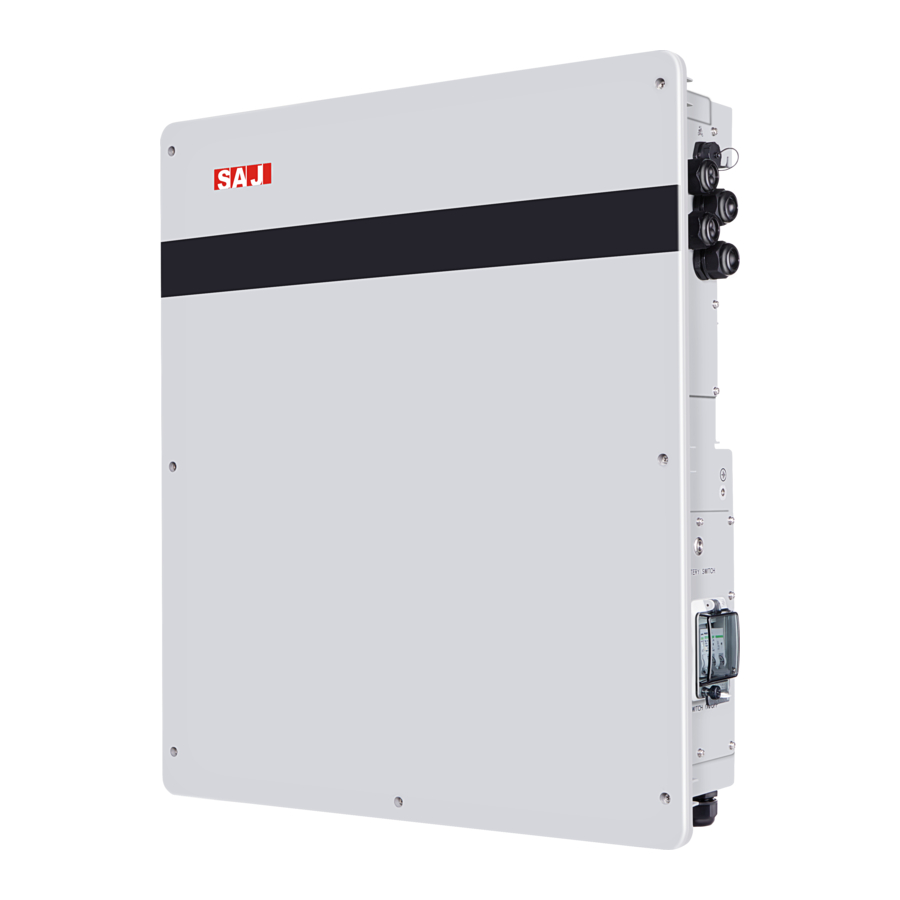
3.2.1 AS1 series product dimension Fig. 3.1 AS1-3KS-5.1 appearance and dimension diagram 3.2.2 AS1-3KS-5.1 is cooled by natural wind convection. It is recommended to install in indoors or sheltered areas to avoid direct sunlight, rain and snow. Fig. 3.2 Installation tips... - Page 12 3.2.3 Vertical ground mounting method is recommended and it’s allowed to be installed by maximum tilting 15° backward. Do not install it horizontally or reversely. Fig. 3.3 Installation angle 3.2.4 Please ensure that the air at the installation point is circulated. Bad air ventilation will affect the working performance of internal electronic components and shorten the service life of AS1.
-
Page 13: Installation Steps
3.3 Installation steps 3.3.1 Determine the mounting hole position of the hanging panel The AS1 series is mounted on a hanging panel. The mounting position is determined according to the position of the hanging hole on the hanging panel. Unit: mm. Fig. - Page 14 Fig. 3.7 AS1-3KS-5.1 (master device) Fig. 3.8 B1-5.1-48 hanging panel dimension (slave device) AS1-3KS-5.1 is the master device and B1-5.1-48 is the slave device. In order to ensure - 13 -...
- Page 15 normal installation of both, the installation distance between the master and the slave panel, while that between the slave panels shall at least meet requirements as follows: Fig. 3.9 Distance between hanging panels - 14 -...
- Page 16 Fix the hanging panel with hex head screw on the installation position. Fig. 3.10 Fixing the hanging panel Please pay attention when installing the device. Please install the slave device first and then install the master device. In case the distance between the master device and the slave device is not enough, installation can’t be done.
- Page 17 Fig. 3.11 Install AS1-3KS-5.1 - 16 -...
-
Page 18: Chapter 4 Electrical Connections
Chapter 4 Electrical Connections 4.1 Electrical Interface Description Fig. 4.1 AS1-3KS-5.1 electrical interfaces Code Name DRMS Port CT/Meter connection RS232 communication Grid connection Backup connection BMS switches Battery switches BAT+ BMS LINK BAT- Table 4.1 Interface description - 17 -... -
Page 19: System Wiring Schematic
4.2 System Wiring Schematic Meter Grid Back-up Fig. 4.2 Wiring schematic diagram Don’t connect the backup loads side with the grid or battery BACKUP BACKUP Fig. 4.3 Wrong connection example 4.3 Master Device Wiring When wiring the master device, you need to disassemble the wiring cover in the upper right corner and connect as per the terminal identification. -
Page 20: Slave Device Wiring
Fig. 4.4 Master device wiring terminals 4.4 Slave Device Wiring More capacity is required to connect the slave devices in parallel. Disconnect the battery connector cover of the master device and the slave unit before wiring. Only 3 lines are required to connect a slave device. (BAT+-BAT+, BAT--BAT-, LINK-LINK) - 19 -... - Page 21 Fig. 4.5 Slave device wiring terminals Notice · Please use the battery cable in original package. · Do not share 1 lithium battery slave device on 2 AS1. - 20 -...
-
Page 22: Communication Interface Description
4.5 Communication Interface Description Fig. 4.6 DRMS pins Pin number Name DRM1/5 DRM2/6 DRM3/7 DRM4/8 REF GEN/0 COM LOAD/0 Table 4.2 DRMS pins description Fig. 4.7 CT/Meter pins - 21 -... - Page 23 Pin number Name R485_A R485_B PV_CT- PV_CT+ Grid_CT- Grid_CT+ Table. 4.3 CT/Meter pins description Fig. 4.8 RS232 pins Pin number Name RS-232 TX RS-232 RX Table 4.4 RS232 pins description Note: The RS232 interface can be connected to the eSolar GPRS/4G/WiFi module. For operation details, please refer to the quick installation guide of each monitoring module.
-
Page 24: Chapter 5 Debugging Instructions
Chapter 5 Debugging Instructions 5.1 Human-computer Interface Introduction 100% Fig. 5.1 Human-computer interface Description LED lamps state Green lamp flicker from Battery discharging bottom to top Green lamp flicker from Battery charging top to bottom Green/Re d LED Red lamp flicker:1 s/time Standby lamp Green lamp and red lamp Procedures are being upgrade... -
Page 25: System Commissioning
5.2 System commissioning After finishing connecting wiring, please install the communication modules. Use eSolar O&M software to realize initialization of the device. (Terminal users please check relevant info by eSolar Air) Notice: before starting slave device, open the battery switches and BMS switches first. 5.3 Remote monitoring The eSolar 4G/WiFi/Ethernet module are connected to the Internet, and the inverter data is uploaded to the server. - Page 26 Explanation Fault type Communication loss of the main and subordinate Error machine Master High temperature Master Error Low temperature Master Error DCI Err Master Error Error Synchronizing pulse fault Master Error Relay fault Master Storage fault Master Error Error Battery input short circuit Master Error Battery overvoltage Master Error...
- Page 27 Alarm Overload alarm Master Fan Err Slave Error Error Output terminal abnormal Slave Inverter voltage wave form fault Error Slave Alarm Grid voltage consistent alarm Slave Grid frequency consistent alarm Alarm Slave Alarm GND Loss Warn Alarm LN Wrong Warn Alarm CAN communication loss Slave Alarm...
-
Page 28: Chapter 7 Battery Maintenance
Alarm Over charging temperature alarm Slave Alarm Battery low voltage alarm Slave Alarm BMS communication loss alarm Slave Alarm Ammeter communication loss alarm Slave Alarm DRM0 alarm Slave Chapter 7 Battery maintenance 7.1 Transportation Lithium batteries are dangerous goods. Passed the test of UN38.3, this product meets the transportation requirements for dangerous goods for lithium batteries. - Page 29 The battery cannot be disposed of as household refuse. When the service life of the battery reaches to the limit, it is not required to return it to the dealer or SAJ, but it must be recycled to the special waste lithium battery recycling station in the area.
-
Page 30: Chapter 8 Contact Us
Chapter 8 Contact Us Guangzhou Sanjing Electric Co., Ltd. Headquarter: SAJ Innovation Park, No.9, Lizhishan Road, Science City, Guangzhou High-tech Zone, Guangdong, P.R.China. Jiangxi Factory: Building D10, D11, Ganzhou International Port Electronic Info Industrial Park, Longling Town, Nankang District, Cangzhou City, Jiangxi Province Website: http://www.saj-electric.com/... -
Page 31: Warranty Card
Warranty Card The installer should fill in the second form while installing the inverter. For warranty claim, please complete the below forms and send this page to SAJ, attached with the Customer’s invoice. For customer to fill in Name: City:... - Page 32 For installer to fill in Modules used: Modules per string: No. of string: Installation company: Contractor license number: Company: City: Country: Zip: Tel: Fax: E-mail: Signature: Date: - 31 -...
- Page 33 Guangzhou Sanjing Electric CO., LTD. ADD: SAJ Innovation Park, No.9, Lizhishan Road, Science City, Guangzhou High-tech Zone, Guangdong, P.R.China (Zip: 510663) Tel: +86 20 6660 8588 Fax: +86 20 6660 8589 Web: http: //www.saj-electric.com Edition No: V1.0...
Need help?
Do you have a question about the AS1-3KS-5.1 and is the answer not in the manual?
Questions and answers