Advertisement
Quick Links
Advertisement

Related Manuals for Intelbras iIVA 5040 AT


Summary of Contents for Intelbras iIVA 5040 AT
- Page 1 User manual IVA 5040 AT IVA 5080 AT...
- Page 2 Both models have more configurations to meet the demands of installation scenarios, always maintaining the quality of Intelbras products. Read the information carefully for the correct use of both sensor models.
- Page 3 » Install the transmitter and receiver so that they are aligned; » LGPD - General Law for the Protection of Personal Data: Intelbras does not access, transfer, capture, or perform any other type of treatment of personal data from this product.
- Page 4 » For installing sensors in perimeters, always follow the sensor layout below: CANAL 2 CHANNEL 2 CANAL 3 CHANNEL 3 CANAL 2 CHANNEL 2 CANAL 2 CHANNEL 2 CANAL 1 CHANNEL 1 CANAL 1 CHANNEL 1 CANAL 2 CHANNEL 2 CANAL 3 CHANNEL 3 »...
- Page 5 » For the IVA 5040 AT sensor, follow the protection distances below: Distance between TX and RX 20 m 40 m Side Protection Distance (DPL) >2 m >3 m >4 m Vertical Protection Distance (DPV) Maximum stacking of 3 sensors »...
-
Page 6: Table Of Contents
Summary 1. Technical specifications 2. Product 3. Installation 4. Troubleshooting Warranty term... -
Page 7: Technical Specifications
1. Technical specifications Model IVA 5040 AT IVA 5080 AT Number of beams Power supply voltage 10 ~ 24 Vdc / Vac (without polarity) Consumption current (TX + RX) ≤65 mA Frequency channels 3 channels, frequencies 1, 2 and 3 External 40 m 80 m... -
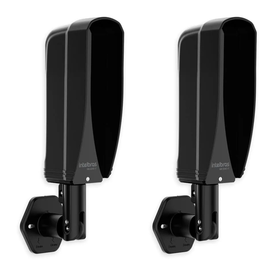
Page 8: Product
2. Product IVA 5080 AT IVA 5080 AT Gabinete Main Cabinet Principal IVA 5040 AT IVA 5040 AT Tampa Front cover Frontal 360° 360° 360° 360° Suporte Articulating Articulável support 180° 180° 180° 180° TEMPO RESPOSTA Alimentação Saída de Alarme Canais de Frequência LED On TX Ajuste do Tempo de Resposta... -
Page 9: Installation
3. Installation 1. For security reasons, it is necessary to open the sensors to identify which is the transmitter and which is the receiver. Here’s how to open the sensor cabinet and perform the necessary identification: IVA 5080 AT IVA 5080 AT TEMPO RESPOSTA Remove the screw... - Page 10 3. Secure the sensors in the installation position following the recommendations below: » Do not install the sensor upside down. » Orient yourself by the positioning arrows located on the articulated sensor support. Down Down Down Down 4. Turn on the power on the receiver and transmitter board (10 ~ 24 Vdc / Vac - no polarity). After that, connect the wires from the alarm output to the zone input of your alarm panel: Transmitter TRANSMISSOR...
- Page 11 6. Perform the Response Time setting . Response time is the time that the infrared barrier must be interrupted to trigger. This setting is only relevant to the receiver: 500 ms 500ms 750 ms 250 ms 750ms 250ms 50 ms 50ms The factory default response time is 50 ms , ie Position 1 .
- Page 12 8. After making the configuration, tighten the screws for fixing the sensor position on both the receiver and the transmitter, as shown in the following figure: Horizontal adjustment attaching Parafuso de fixação ajuste horizontal screw Parafuso de travamento Locking screw Vertical adjustment attaching Parafuso de fixação ajuste vertical...
-
Page 13: Troubleshooting
4. Troubleshooting Follow the steps outlined below to troubleshoot your sensor: 1. Check that the installation distance is within the specified. In environments with a high rate of rain or fog, it is recommended that the installation distance be 50% of the maximum distance for outdoor environments; 2. -
Page 14: Warranty Term
8. After its useful life, the product must be delivered to an authorized Intelbras service center or directly disposed of in an environmentally appropriate manner to avoid environmental and health impacts. If you prefer, the battery, as well as other unused Intelbras brand electronics, can be disposed of at any Green Eletron collection point (waste management facility to which we are associated). - Page 15 Support via e-mail: suporte@intelbras.com.br Customer Service: 0800 7042767 Where to buy? Who installs it? 0800 7245115 Imported to Brazil by: Intelbras S/A – Indústria de Telecomunicação Eletrônica Brasileira Rodovia SC 281, km 4,5 – Sertão do Maruim – São José/SC – 88122-001 01.21 CNPJ 82.901.000/0014-41 –...
Need help?
Do you have a question about the iIVA 5040 AT and is the answer not in the manual?
Questions and answers