Table of Contents

Subscribe to Our Youtube Channel
Related Manuals for GALLERY Classic Eco


Summary of Contents for GALLERY Classic Eco
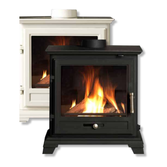
- Page 1 Classic Eco Gas Stove For use in UK & Ireland on Natural Gas (G20) at a supply pressure of 20mbar or Propane (G31) at a supply pressure of 37mbar PLEASE LEAVE THIS BOOKLET WITH THE CUSTOMER GBU / REV :C / 01/21...
-
Page 3: Table Of Contents
Contents INSTALLATION INSTRUCTIONS IMPORTANT NOTES PAGE 04 TECHNICAL INFORMATION PAGE 05 DIMENSIONS PAGE 06 INSTALLATION PAGE 07 COMMISSIONING THE STOVE PAGE 12 CHECK FOR SPILLAGE PAGE 14 CUSTOMER HANDOVER PAGE 15 SERVICING PAGE 16 SERVICE AND MAINTENANCE LOG PAGE 18 COMMISSIONING CHECK LIST PAGE 20 USER INSTRUCTIONS... -
Page 4: Installation Instructions
Installation Instructions IMPORTANT NOTES This stove is a log fuel effect radiant convector only. Before installation, ensure that the local gas supply distribution network is adequate and that the appliance can be installed as such to ensure it meets the safe working parameters as indicated on the appliance data badge. The data badge is located at the rear of the stove. -
Page 5: Technical Information
The stove is fitted with a spillage monitoring system consisting of a thermal switch. This system is not adjustable, and must not be put out of action when the appliance is in operation, if the switch is removed it would be deem the appliance to be unsafe and must immediately be disconnected from the gas supply and a warning notice issued. -
Page 6: Dimensions
Dimensions GAS CLASSIC ECO STOVE... -
Page 7: Installation
Installation Install the stove in accordance with the requirements given below. The gas connection will be to the rear of the stove therefore it is advisable to prepare the pipe work in advance of installing the stove. Fix the legs to the stove using the bolts provided. When the stove is in the desired position, if required, fix the brackets provided to the back feet and level the stove using the levelling screws, then mark the hearth through the holes, remove the stove, and drill and plug the hearth for securing the stove. - Page 8 FITTING THE THERMAL SWITCH GUARD Using the two screws already fitted to the rear of the stove, secure the thermal switch guard to the rear of the appliance. See Fig. 4 Fig.4 Fitting the thermal switch guard POSITIONING THE STOVE Clearances from non-combustible material in the fireplace opening must be at least 160mm on the left side, 160mm on the right hand side and 105mm at the back.
- Page 9 HEARTH The stove must stand on a fireproof hearth made of non-combustible material of a minimum thickness 12mm and be of sufficient size to accommodate the stove. It should be a minimum of 300mm from the candescent flame of the appliance FIRE SURROUND &...
- Page 10 FLUE RESTRICTOR RING This stove is supplied with a flue restrictor ring. The restrictor ring must not be fitted if the stove is to be connected to a pre-cast flue or a masonry chimney with a diameter of 100mm/125mm. There may however be certain circumstances where fitting the restrictor ring causes the fire to fail the spillage test.
- Page 11 POSITIONING THE LOGS 1. Fit log A as shown in Fig.8. 2. The Embaglow can now be fitted on top of the black vermiculite as directed on the back of the packet. Take care not to put Embaglow material too near the pilot as this can interfere with ignition. 3.
-
Page 12: Commissioning The Stove
Commissioning the stove MANUALLY OPERATED STOVES Once the fire is in place, connected, flued correctly, and the logs are in place, you can proceed with lighting the stove and ensuring all the features are working correctly. The control knob is located behind the right-hand foot of the stove. The pilot light is centrally located. - Page 13 TURNING THE STOVE TO PILOT From any heat setting, depress control knob fully and turn clockwise to PILOT position. Disconnect. TURNING THE STOVE OFF From any heat setting or the PILOT position, depress control knob fully and turn clockwise to OFF position.
-
Page 14: Check For Spillage
To stop the fire, simply press the power button again and the burner will stop. Disconnect the pressure gauge, replace the test point sealing screw and test for gas soundness. Once the fire has been successfully lit and extinguished, you can then put batteries in the remote control and check that this is functioning correctly (see user instructions including how to set the time and date on the handset). -
Page 15: Customer Handover
CUSTOMER HANDOVER Hand these instructions to the customer and advise the customer how to use the stove. Explain to the customer that the stove has a flame failure and spillage monitoring system. Advise that if the monitoring system repeatedly shuts off the stove, it must be switched off and not used until it has been inspected by a competent person. -
Page 16: Servicing
Servicing It is essential that the stove is regularly serviced, and the flue system checked by a qualified person. An annual service is recommended as a minimum but not limited to. SERVICING INSTRUCTIONS The stove is fitted with a spillage monitoring system consisting of a thermal switch connected to a thermocouple interrupter. - Page 17 • Close the stove door, replace the screw securing the door • Check the supply pressure as described in the TECHNICAL INFORMATION section (P.5) • Complete a gas tightness test • Check all controls, safety devices including the flame picture and that the fire is working safely accordance with the manufacturer’s instructions •...
-
Page 18: Service And Maintenance Log
SERVICE AND MAINTENANCE LOG SERVICE DATE PERFORMED BY WORK PERFORMED... - Page 19 SERVICE DATE PERFORMED BY WORK PERFORMED...
-
Page 20: Commissioning Checklist
COMMISSIONING CHECKLIST This checklist must be completed by the installer and handed to the customer for future reference. Customer Name: Telephone: Address: Appliance make and model: Appliance serial number: Commissioned by: Gas Safe register no.: Company Name: Telephone: Company address: Commissioning date: Gas Safe register notification no.: Site Requirements... - Page 21 Hearth Requirements Is the hearth constructed from non-combustible material and protection sufficiant? Is the hearth a minimum of 12mm thick with a minimum floor to top surface of 50mm (BS5871) or as per manufacturer’s instructions? Firebox and Fuel bed Has the fuel bed (logs, vermiculite) been fitted to the manufacturer’s instructions? Gas Supply Has an isolation tap/restrictor inlet elbow been fitted for servicing? Has the gas supply been thoroughly purged prior to connection to remove any debris?
-
Page 22: User Instructions
User instructions GENERAL NOTES This stove has been individually designed to add charm and character to your home. Providing a highly efficient heat source, the stove has the look and charm of a wood burning stove coupled with the convenience of clean burning gas. Due to the newness of materials the stove may give off a slight smell for a period of time after commissioning. -
Page 23: Remote Control Stove
LIGHTING THE PILOT Depress control knob fully. Whilst depressed turn knob slowly through 90° anticlockwise to PILOT setting. A click will be heard and the piezo spark should light the pilot. Repeat until pilot is visibly lit. If necessary the operation of the spark can be viewed by temporarily opening the front door. Keep knob depressed at this point for 10-15 seconds and release the knob. - Page 24 STOVE CONTROL UNIT Battery compartment cover opening lever White power isolator switch (sliding) Indicator light Battery compartment cover Increase flame Decrease flame Power Button INDICATOR LIGHT • Off - Burner is in standby and ready for start, or already in continuous operation •...
- Page 25 REMOTE CONTROL HANDSET Mode- MAN (Manual), Zzz (Snooze), thermostat or timed Time (12 hour or 24 display) Day of the week Gas fire burner status In range of fire (missing if not in range or if Fire Battery condition- Control turned off) RC handset, FC fire control Room Temperature...
- Page 26 DETAILED USER INSTRUCTIONS SETTING THE REMOTE CONTROL HANDSET Upon successful insertion of the batteries in the handset the display will be as shown in Fig. 5. The handset will be supplied paired to the fire and all that is required is to set the time of day and select if a 24h hour clock or 12 hour clock display is required and if temperature display is on Celsius or Fahrenheit.
- Page 27 SETTING THE TEMPERATURE DISPLAY TO CELSIUS OR FAHRENHEIT. Press and release the + or - button to toggle between °C and °F. When the display shows the desired symbol, press and release the SET button to store the setting. As the main settings above have now been done, press and hold (not releasing straight away) the “SET” button for a few seconds and this will exit the setup menu.
- Page 28 FACTORY RESET OF DISPLAY HANDSET To reset a handset to factory conditions to enable it to be paired with a control: • Hold the handset to unlock. Press and hold SET until handset beeps and release the set button. PROG will be at the top left corner •...
-
Page 29: Battery Replacement
THERMOSTATIC MODE Thermostatic mode will allow you to set a desired temperature for the stove to maintain. Once the temperature is reached the fire will reduce the power to minimum and regulate itself to maintain the temperature. The timed thermostat can be set before or during manual operation of the fire. Hold the handset to unlock as described previously and press the mode button as many times as necessary until the THERMOSTAT symbol is flashing at the top of the display. -
Page 30: Glass Cleaning
If an E code is displayed, allow the fire to cool and perform a normal start attempt to reset the control to standby. Then perform a normal start attempt again to see if the fire has cleared the error and the fire is functioning correctly. If the ERROR does not clear, it is essential before undertaking any actions on the servicing as detailed below, that the batteries being used are good and should be replaced with new ones to be sure that is not the problem. - Page 32 PLEASE LEAVE THIS BOOKLET WITH THE CUSTOMER Percy Doughty & Co Imperial Point, Express Trading Estate, Stone Hill Road, Farnworth, Bolton. BL4 9TN Tel: 01204 868 550 Fax: 01204 868 551 Email: sales@percydoughty.com Website: www.thegallerycollection.co.uk GBU / REV :C / 12/20...
Need help?
Do you have a question about the Classic Eco and is the answer not in the manual?
Questions and answers