Bender ISOMETER isoMIL425HV Manual
Insulation monitoring device for unearthed ac, ac/dc and dc systems (it systems) for military applications up to 3(n)ac, ac 690 v, dc 1000 v
Hide thumbs
Also See for ISOMETER isoMIL425HV:
- Manual (33 pages) ,
- Manual (48 pages) ,
- Quick start manual (13 pages)
Table of Contents
Advertisement
Quick Links
Advertisement
Table of Contents

Related Manuals for Bender ISOMETER isoMIL425HV


Summary of Contents for Bender ISOMETER isoMIL425HV
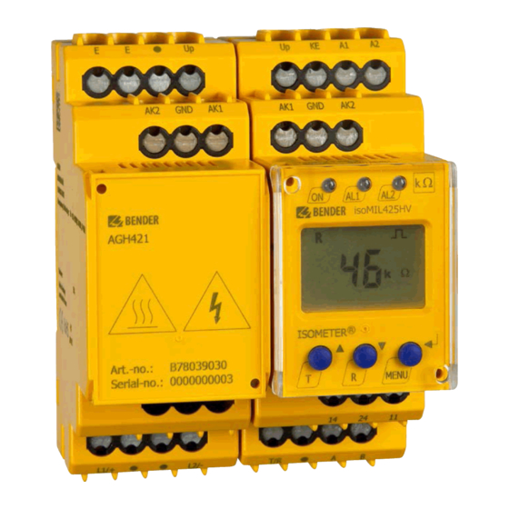
- Page 1 Manual ISOMETER® isoMIL425HV with coupling device AGH421 Insulation monitoring device for unearthed AC, AC/DC and DC systems (IT systems) for military applications up to 3(N)AC, AC 690 V, DC 1000 V Software version: D0460 V1.xx isoMIL425HV_D00204_05_M_XXEN/02.2021...
- Page 2 Bender GmbH & Co. KG Londorfer Str. 65 • 35305 Grünberg • Germany PO box 1161 • 35301 Grünberg • Germany Tel.: +49 6401 807-0 Fax: +49 6401 807-259 E-mail: info@bender.de Web: https://www.bender.de © Bender GmbH & Co. KG All rights reserved.
-
Page 3: Table Of Contents
Table of Contents 1. Important information ..................6 How to use this manual ................. 6 Technical support: Service and support ..........7 1.2.1 First level support ..................... 7 1.2.2 Repair service ..................... 7 1.2.3 Field service ......................8 Training courses ....................8 Delivery conditions .................. - Page 4 Table of Contents 3.2.10 Fault memory ....................22 3.2.11 History memory HiS ..................22 3.2.12 Interface/protocols ..................22 4. Installation, connection and commissioning ........... 24 Installation ....................... 24 Wiring diagram ....................26 Commissioning ....................28 5. Operation of the device ................29 Display elements ...................
- Page 5 Table of Contents 7. Data access using the Modbus RTU protocol ........... 40 Reading out the Modbus register from the ISOMETER® ....40 7.1.1 Command of the master to the ISOMETER® ........40 7.1.2 The ISOMETER® answers the master ............41 Writing the Modbus register (parameter setting) ......
-
Page 6: Important Information
1 Important information 1.1 How to use this manual This manual is intended for electrically skilled persons working in electrical engineering and electro- nics. Always keep this manual within easy reach for future reference. To make it easier for you to understand and revisit certain sections in this man- ual, we have used symbols to identify important instructions and information. -
Page 7: Technical Support: Service And Support
1.2 Technical support: Service and support For commissioning and troubleshooting Bender offers you: 1.2.1 First level support Technical support by phone or e-mail for all Bender products Questions concerning specific customer applications Commissioning ... -
Page 8: Field Service
**Mon-Thurs 7.00 a.m. - 8.00 p.m., Fr 7.00 a.m. - 13.00 p.m. 1.3 Training courses Bender is happy to provide training regarding the use of test equipment. The dates of training courses and workshops can be found on the Internet at www.bender.de ->... -
Page 9: Delivery Conditions
ZVEI (Zentralverband Elektrotechnik- und Elektronikindus- trie e.V.) (German Electrical and Electronic Manufacturers' Association) also applies. Sale and delivery conditions can be obtained from Bender in printed or electronic format. 1.5 Inspection, transport and storage Inspect the dispatch and equipment packaging for damage, and compare the contents of the package with the delivery documents. -
Page 10: Disposal
13th August 2005 must be taken back by the manufacturer and disposed of prop- erly. For more information on the disposal of Bender devices, refer to our homepage at www.bender.de -> Service & support. isoMIL425HV_D00204_05_M_XXEN/02.2021... -
Page 11: Safety Instructions
2 Safety instructions 2.1 General safety instructions Part of the device documentation in addition to this manual is the enclosed "Safety instructions for Bender products". 2.2 Work activities on electrical installations Only skilled persons are permitted to carry out the work necessary to install, commission and run a de- vice or system. -
Page 12: Intended Use
Safety instructions 2.3 Intended use The ISOMETER® of the isoMIL425HV series monitors the insulation resistance of unearthed AC/DC main circuits (IT systems) with nominal system voltages of 3(N)AC, AC/DC 0 … 690 V or DC 0 …1000 V, 15…460 Hz. DC components existing in 3(N)AC, AC/DC systems do not influence the operating characteristics when a minimum load current of DC 10 mA flows. -
Page 13: Function
RS-485 (galvanically isolated) including the following protocols: – BMS interface (Bender measuring device interface) for data exchange with other Bender components – Modbus RTU – IsoData (for continuous data output) Password protection to prevent unauthorised parameter changes ... -
Page 14: Functional Description
Function 3.2 Functional description The ISOMETER® measures the insulation resistance R and the system leakage capacitance C between the system to be monitored (L1/+, L2/-) and earth (PE). The RMS value of the nominal system voltage U between L1/+ and L2/- as well as the residual voltages U (between L1/+ and earth) and U (between L2/- and earth) are also measured. -
Page 15: Monitoring The Insulation Resistance
Function If the values R or U do not violate their release value (response value plus hysteresis) for the period t without interruption, the alarm relays will switch back to their initial position and the alarm LEDs "AL1"/"AL2" stop lighting. The ISOMETER®... -
Page 16: Undervoltage/Overvoltage Monitoring
Function 3.2.2 Undervoltage/overvoltage monitoring In the menu "AL" (see chapter 5.3), the parameters ("U <" and "U >") for monitoring the mains voltage can be activated or deactivated. The maximum undervoltage value is limited by the overvoltage value. The RMS value of the mains voltage is monitored. If the mains voltage U reaches, falls below or exceeds the limit values ("U <"... - Page 17 Function Error codes If, contrary to expectations, a device error should occur, error codes will ap- pear on the display. Some of these are described below: Error code Description PE connection fault The connections "E" or "KE" to earth are interrupted. E.01 Action: Check connection, eliminate fault.
- Page 18 Function After eliminating the fault, the alarm relays switch back automatically or by pressing the reset button. The self test can take a few minutes. The self test can be suppressed for the du- ration of the device start by setting the parameter in the menu "SEt" to "S.Ct = off".
-
Page 19: Malfunction
LEDs "ON"/"AL1"/ "AL2" will flash. If the error occurs again after restarting the device or after restoring the facto- ry settings, please contact Bender Service. 3.2.5 Signalling assignment of the alarm relays K1/K2 The messages "device error", "insulation fault", "insulation impedance fault",... -
Page 20: Measuring And Response Times
Function 3.2.6 Measuring and response times The measuring time is the period essential for the detection of the measured value. The measuring time is reflected in the operating time t The measuring time for the insulation resistance value is mainly determined by the required measuring pulse duration, which depends on the insulation resistance R and system leakage capacitance C... -
Page 21: Password Protection (On, Off)
Function Delay on release The delay on release t can be set uniformly for all messages in the menu "t" using the parameter "toff". An alarm will continuously be signalled until the threshold value of the re- spective measuring value is not violated (including hysteresis) for the period of t without interruption. -
Page 22: Fault Memory
The ISOMETER® uses the serial hardware interface RS-485 with the following protocols: The BMS protocol is an essential component of the Bender measuring device interface (BMS bus protocol). Data transmission generally makes use of ASCII characters. Modbus RTU ... - Page 23 Function IsoData The ISOMETER® continuously sends an ASCII data string with a cycle of approximately 1 s. Communication with the ISOMETER® within this mode is not possible and no additional transmitter may be connected to the RS-485 bus cable. The ASCII data string for the ISOMETER® is de- scribed in chapter 9 The device address, baud rate and parity for the interface protocols are con-...
-
Page 24: Installation, Connection And Commissioning
4 Installation, connection and commissioning Risk of electric shock! Touching uninsulated live conductors can result in death or serious injury. Therefore avoid any physical contact with DANGER active conductors and ensure compliance with the regulations for working on electrical installations. 4.1 Installation DIN rail mounting: ... - Page 25 Installation, connection and commissioning The dimension diagram, sketch for screw mounting and DIN rail mounting are shown on the following page: Click! Click & All dimensions in mm The front plate cover can be opened at the lower part marked with an arrow. isoMIL425HV_D00204_05_M_XXEN/02.2021...
-
Page 26: Wiring Diagram
Installation, connection and commissioning 4.2 Wiring diagram Only one ISOMETER® may be controlled with an external stop switch between terminals "F" and "Up". The connection has to be potential-free since the "Up" terminal may not be CAUTION connected to other ISOMETER®s. L1/+ L2/- Stop... - Page 27 Installation, connection and commissioning Danger from touching hot surfaces! If the AGH421 is operated at system voltages > 800 V, the temperature of the enclosure may exceed 60 °C. CAUTION Once the device is connected to mains voltage avoid touching the device's surfaces. For details about the conductor cross sections required for wiring, refer to the technical data from page...
-
Page 28: Commissioning
Installation, connection and commissioning 4.3 Commissioning 1. Check that the ISOMETER® is properly connected to the system to be monitored. 2. Connecting supply voltage U to the ISOMETER® The device carries out a calibration, a self test and adjusts itself to the IT system to be monitored. -
Page 29: Operation Of The Device
5 Operation of the device The menu structure is illustrated schematically on the following pages. After pressing the "MENU" button for > 1.5 s, the first "AL" menu item appears. (Enter) buttons for navigation and settings. Up and down button: - Navigate up or down in the menu settings - Increase or decrease values Pressing the MENU/Enter button for more than... -
Page 30: Display Elements
Operation of the device 5.1 Display elements Device front/display Function green - on Assignment according to yellow - alarm table on page 33 yellow - alarm AL1 AL2 Up button Test button ( press > 1.5 s) Down button Reset button (press > 1.5 s) ENTER MENU button (press >... -
Page 31: Menu Structure
Operation of the device 5.2 Menu structure > < 1.5 s > > 1.5 s 1.5 s . . . < t > 5 Min. < > 1.5 s Z [kΩ] R [kΩ] C [μF] U L1 L2 [V ] <... -
Page 32: Al" Menu
Operation of the device 5.3 "AL" menu 5.3.1 Response value setting The two parameters that monitor the insulation resistance, "R1" and "R2", can be found in the menu "AL". The value R1 can only be set higher than the value R2. -
Page 33: Out" Menu
Operation of the device 5.4 "out" menu 5.4.1 Configuration of the relay operating mode Relay K1 Relay K2 Description Display Display Operating mode of n.o. n.o. the relay n.c./n.o. FAC = Factory settings; Cs = Customer settings 5.4.2 Relay signalling assignment "r1" and "r2" and LED assign- ment In the alarm assignment, each alarm is assigned to the corresponding relay with the setting "on". -
Page 34: Fault Memory Configuration
Operation of the device Alarm K1 "r1" K2 "r2" LEDs description Display Display ON AL1 AL2 Alarm U < V U < V Undervoltage Alarm U > V U > V Overvoltage Manually ... -
Page 35: Interface Configuration
Operation of the device 5.4.4 Interface configuration Display Setting value Description Value range FAC Adr = 0 deactivates BMS as well as Modbus and acti- 0/3 … 90 vates isoData with continu- Adr. ous data output (115k2, 8E1) "---" : BMS bus (9k6, 7E1) ---/ Baud Adr 1... -
Page 36: T" Menu
Display Activation Setting value Description Range Password for 0 . . . 999 parameter setting Test of the system connec- tion during device test Restore factory settings For Bender Service only FAC = Factory settings; Cs = Customer settings isoMIL425HV_D00204_05_M_XXEN/02.2021... -
Page 37: Measured Value Display And History Memory
Operation of the device 5.7 Measured value display and history memory All other measured value displays switch to the standard display (insulation resistance) after a maximum of 5 min. The pulse symbol indicates a current measured value. If this symbol does not appear, the measurement is still run- ning and the latest valid measured value will be displayed. - Page 38 Display Description Insulation resistance 1 kΩ … 5 MΩ Resolution 1 kΩ/10 kΩ is an approximate value for asymmetrical insula- tion faults and can be used as a trend indicator with short measuring times. It is determined by the DC mains U R = kΩ...
-
Page 39: Data Access Using The Bms Protocol
6 Data access using the BMS protocol The BMS protocol is an essential component of the Bender measuring device interface (BMS bus protocol). ASCII characters are used for data transfer. BMS channel Operation value Alarm Pre-alarm R1 Alarm R2 Undervoltage Overvoltage Connection fault earth (E.01) -
Page 40: Data Access Using The Modbus Rtu Protocol
7 Data access using the Modbus RTU protocol Requests to the ISOMETER® can be made using the function code 0x03 (Read Holding Registers) or the function code 0x10 (Write Multiple Registers). The ISOMETER® generates a function-related answer and sends it back. 7.1 Reading out the Modbus register from the ISOMETER®... -
Page 41: Command Of The Master To The Isometer
Data access using the Modbus RTU protocol 7.1.2 The ISOMETER® answers the master Byte Name Example Byte 0 ISOMETER® Modbus address 0x03 Byte 1 Function code 0x03 Byte 2 Number of data bytes 0x02 Byte 3, 4 Data 0x0047 Byte 7, 8 CRC16 Checksum 0x81B6 7.2 Writing the Modbus register (parameter setting) -
Page 42: The Isometer® Answers The Master
Data access using the Modbus RTU protocol 7.2.2 The ISOMETER® answers the master Byte Name Example Byte 0 ISOMETER® Modbus address 0x03 Byte 1 Function code 0x10 Byte 2, 3 Start register 0x0BBB Byte 4, 5 Number of registers 0x0001 Byte 6, 7 CRC16 Checksum 0x722A... -
Page 43: Modbus Register Assignment Of The Isometer
8 Modbus register assignment of the ISOMETER® Depending on the device condition, the information in the registers is the measured value without alarm; the measured value with alarm 1; the meas- ured value with alarm 2; or only the device fault. Measured value Register Device fault... - Page 44 Modbus register assignment of the ISOMETER® Measured value Register Device fault Without Alarm 1 Alarm 2 alarm 1016 Voltage (76) [no alarm] 1019 1020 Voltage (76) [no alarm] 1023 Fault location 1024 in % --- (1022) 1027 [no alarm] 1028 Insulation fault (71) 1031...
- Page 45 Modbus register assignment of the ISOMETER® Property Description Format Unit Value range Register 3000 Reserved 3001 Reserved 3002 Reserved 3003 Reserved 3004 Reserved Pre-alarm value 3005 resistance meas- UINT 16 kΩ R2 … 500 urement "R1" 3006 Reserved Alarm value 3007 resistance meas- UINT 16...
- Page 46 Modbus register assignment of the ISOMETER® Property Description Format Unit Value range Register Operating mode 0 = n.o. 3014 UINT 16 of relay 2 "r2" 1 = n.c. 3015 Bus address "Adr" UINT 16 0/3 … 90 0 = BMS 1 = 1.2 k 2 = 2.4 k 3 = 4.8 k...
- Page 47 Modbus register assignment of the ISOMETER® Property Description Format Unit Value range Register Test of the sys- tem connection 0 = Inactive 3024 UINT 16 during device test 1 = Active "nEt" 3025 Reserved Request stop mode (0 = deacti- 0 = Stop 3026 UINT 16...
- Page 48 Modbus register assignment of the ISOMETER® Property Description Format Unit Value range Register Software version 9821 UINT 16 number Software version: 9822 UINT 16 Year Software version: 9823 UINT 16 Month Software version: 9824 UINT 16 Modbus driver 9825 UINT 16 version RW = Read/Write;...
-
Page 49: Device-Specific Data Type Of The Isometer
Modbus register assignment of the ISOMETER® 8.1 Device-specific data type of the ISOMETER® 8.1.1 Device name The data format of the device name is specified below. Word 0x01 0x02 0x03 ------------------- 0x08 0x09 0x00 10 Words in total Each Word contains two ASCII characters 8.1.2 Measured values Each measured value is available as a channel and consists of 8 bytes (4 regis-... -
Page 50: Float = Floating Point Value Of The Channels
Modbus register assignment of the ISOMETER® 8.1.2.1 Float = Floating point value of the channels 0x00 0x01 HiByte LoByte HiByte LoByte S E E E E E E E E M M M M M M M M M M M M M M M M M M M M M M M Representation of the bit order for processing analogue measured values ac- cording to IEEE 754 S = Sign;... -
Page 51: At&T = Alarm Type And Test Type (Internal/External)
Modbus register assignment of the ISOMETER® 8.1.2.2 AT&T = Alarm type and test type (internal/external) Description No alarm Prewarning Device error Reserved Warning Alarm Reserved … … … Reserved Reserved No test Internal test External test The alarm type is coded by the bits 0 to 2. Bits 3, 4 and 5 are reserved and al- ways have the value 0. -
Page 52: R&U = Range And Unit
Modbus register assignment of the ISOMETER® 8.1.2.3 R&U = Range and unit Description Invalid (init) No unit Ω Baud °C °F Second Minute Hour Month Actual value The actual value is lower The actual value is higher Invalid value The units of the bits 0 to 4 are coded. ... -
Page 53: Alarm Assignment Of The Relays
Modbus register assignment of the ISOMETER® 8.1.3 Alarm assignment of the relays Several alarms can be assigned to each relay. For the assignment of each relay, a 16-bit register is used with the bits described below. The following table ap- plies to relay 1 and relay 2, in which "x"... -
Page 54: Channel Descriptions
Display indication Description When reading, always 0 Reserved When writing, any value When reading, always 0 Reserved When writing, any value When reading, always 0 Reserved When writing, any value 8.2 Channel descriptions Measured value description/alarm Value Note message operating message 1 (0x01) Insulation fault... - Page 55 Modbus register assignment of the ISOMETER® To convert parameter data, data type descriptions are required. Text repre- sentation is not necessary in this case. Value Description of parameters 1023 (0x3FF) Parameter/measured value invalid. The menu item of this parameter is not displayed. 1022 (0x3FE) No measured value/no message 1021 (0x3FD) Measured value/parameter inactive 1020 (0x3FC) Measured value/parameter only temporarily inactive (e.g.
-
Page 56: Isodata Data String
9 IsoData data string In IsoData mode, the ISOMETER® continuously sends the whole data string with a cycle time of approximately 1 s. Communication with the ISOMETER® in this mode is not possible and no additional sender may be connected via the RS-485 bus cable. - Page 57 IsoData data string String Description Alarm message [hexadecimal] (without leading "0x") The alarms are included in this value with the OR function. Assignment of the alarms: 0x0002 Device fault 0x0004 Prewarning insulation resistance R at L1/+ 0x0008 Prewarning insulation resistance R at L2/- 0x000C Prewarning insulation resistance R symmetrical...
-
Page 58: Technical Data
10 Technical data 10.1 Tabular representation ( )* = Factory settings Insulation coordination acc. to IEC 60664-1/IEC 60664-3 Definitions: Supply circuit (IC2) ............................A1, A2 Output circuit (IC3)........................... 11, 14, 24 Control circuit (IC4) ..................... Up, KE, T/R, A, B, AK1, GND, AK2 Rated voltage................................ - Page 59 Technical data IT system being monitored Nominal system voltage with AGH421-W..........3(N)AC, AC 0…690 V/DC 0…1000 V Tolerance of ........................... AC +15 %, DC +10 % Nominal system voltage range with AGH42x (UL508)..............AC/DC 0…600 V Frequency range of ........................DC, 15…460 Hz Measuring circuit Permissible system leakage capacitance ....................
- Page 60 Technical data Operating uncertainty........................ ±15 %, at least ±2 μF Password ............................off/0…999 (0, off)* Fault memory alarm messages ........................on/(off)* Interface Interface/protocol ....................RS-485/BMS, Modbus RTU, isoData Baud rate ............. BMS (9.6 kbit/s), Modbus RTU (selectable), isoData (115.2 kbit/s) Cable length (9.6 kbit/s) ..........................
- Page 61 Technical data Connection Connection type..........................push-wire terminal Nominal current..............................≤ 10 A Cross section ..............................AWG 24-14 Stripping length..............................10 mm rigid ................................. 0.2…2.5 mm flexible without ferrules........................0.75…2.5 mm flexible with ferrules with/without plastic sleeve ................0.25…2.5 mm Multi-conductor flexible with TWIN ferrules with plastic sleeve............0.5…1.5 mm Opening force................................
- Page 62 Technical data Technical data AGH421 Insulation coordination acc. to IEC 60664-1/IEC 60664-3 Definitions: Measuring circuit (IC1) .......................... L1/+, L2/- Control circuit (IC2)........................ AK1, GND, AK2, Up, E Rated voltage ...............................1,000 V Overvoltage category..............................III Rated impulse voltage: IC1/(IC2)................................8 kV Rated insulated voltage: IC1/(IC2)................................
- Page 63 Technical data Classification of mechanical conditions acc. to IEC 60721: Stationary use (IEC 60721-3-3) ..........................3M12 Transport (IEC 60721-3-2)............................2M4 Long-term storage (IEC 60721-3-1)........................1M12 Connection Connection type ..........................screw-type terminal Screw-type terminals: Nominal current..............................≤ 10 A Cross section .............................AWG 24…12 Stripping length ..............................8 mm rigid/flexible............................
-
Page 64: Standards, Approvals And Certifications
Technical data Other Operating mode..........................continuous operation Mounting ..................... cooling slots must be ventilated vertically > 800 V ............... ≥ 30 mm Distance to adjacent devices from Degree of protection DIN EN 60529, internal components ..................IP30 Degree of protection, terminals (DIN EN 60529) ....................IP20 Enclosure material ............................polycarbonate DIN rail mounting acc. -
Page 65: Ordering Details
Technical data 10.3 Ordering details Type Version Art. No. isoMIL425HV-D4W-4 with AGH421-W Push-wire terminal B71036305W Mounting clip for screw fixing (1 piece per device) B98060008 10.4 Revision history Valid from Document Date software State/Changes version version 06.2015 D0460 V1.xx First edition Chapter 10.1: Section „Connection“, 07.2015 D0460 V1.xx... - Page 66 Technical data Valid from Document Date software State/Changes version version Chapter 3.2: Formula to calculate par- tial resistances Chapter 3.2.9: Description external stop switch Chapter 5.5.1: Description parameter „t“ 05.2018 D0460 V1.xx Chapter 8: Value range Modbus regis- ter 3011 Chapter 10.1: Information „Tolerance of U “...
- Page 67 Technical data isoMIL425HV_D00204_05_M_XXEN/02.2021...
- Page 68 INDEX AGH421 Factory settings 21 - Technical data 62 Fault memory 22 Functional description 14 Commissioning 28 Configuration 33 History memory 22 - Fault memory 34 How to use this manual 6 - Function 36 - Interface 35 Installation 24 - Relay operating mode 33 Interface/protocols - Time 36...
- Page 69 Malfunction 19 Safety instructions 11 Measuring times 20 Self test 16 Menu - Automatic 18 - "AL" 32 - Manual 18 - "out" 33 Signalling assignment of the alarm relays - "SEt" 36 K1/K2 19 - "t" 36 Start-up delay 21 Menu structure 31 Stop switch 15 Modbus...
- Page 71 Bender GmbH & Co. KG Londorfer Str. 65 • 35305 Gruenberg • Germany P.O. Box 1161 • 35301 Gruenberg • Germany Tel.: +49 6401 807-0 Fax: +49 6401 807-259 E-mail: info@bender.de Web: http://www.bender.de Photos: Bender archive.
Need help?
Do you have a question about the ISOMETER isoMIL425HV and is the answer not in the manual?
Questions and answers