
Related Manuals for Bender ICC1324


Summary of Contents for Bender ICC1324
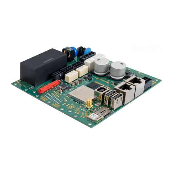
- Page 1 ICC1324 charge controller Charge controller for charging stations and wallboxes for electric vehicle charging Image similar ICC1324_D00436_00_M_XXEN / 05.2022 Manual EN...
- Page 2 Service and support for Bender products First-level support Technical support Carl-Benz-Strasse 8 • 35305 Grünberg • Germany Telephone: +49 6401 807-760 0700BenderHelp * Fax: +49 6401 807-629 E-mail: support@bender-service.de Available on 365 days from 7.00 a.m. to 8.00 p.m. (MEZ/UTC +1) * Landline German Telekom: Mon-Fri from 9.00 a.m.
-
Page 3: Table Of Contents
Signs and symbols ......................5 Training courses and seminars.................5 Delivery conditions .......................5 Inspection, transport and storage ................5 Warranty and liability....................6 Disposal of Bender devices ..................6 Safety ..........................6 Function ....................7 Intended use ........................7 Product features (depending on the variant) .............7 Product description ......................8 Functional description ....................8... - Page 4 4.3.11 Control Pilot (CP) and Proximity Pilot (PP) connections ......19 4.3.12 I/O extension ........................ 19 4.3.13 Emergency opener ....................19 4.3.14 Residual direct current monitoring module (RDC-M)........19 4.3.15 Connectivity with Modbus meters ..............19 4.3.16 Gateway variants with modem ................20 4.3.17 Antenna socket ......................
-
Page 5: General Instructions
Training courses and seminars www.bender.de/en -> Know-how -> Seminars. Delivery conditions The conditions of sale and delivery set out by Bender apply. These can be obtained from Bender in printed or electronic format. The following applies to software products: "Softwareklausel zur Überlassung von Standard- Software als Teil von Lieferungen, Ergänzung und Änderung der Allgemeinen Lieferbedingungen für Erzeugnisse und... -
Page 6: Inspection, Transport And Storage
• Non-observance of technical data. • Repairs carried out incorrectly • Use of accessories and spare parts not recommended by Bender • Catastrophes caused by external influences and force majeure. • Mounting and installation with device combinations not recommended by the manufacturer. -
Page 7: Function
The default passwords should be changed to prevent unauthorised access. Intended use The ICC1324 charge controller, hereinafter referred to as "charge controller", is the main component of a charging system. It is intended for use in charging stations and wallboxes for electric vehicle charging. The charge controller controls type 1 and type 2 socket-outlets as well as attached cables. -
Page 8: Product Description
Function • Integrated WiFi module and two Ethernet interfaces • Integrated DC 12 V voltage source for customer-specific applications • Supply voltage AC 230 V Product description The charge controller monitors the internal hardware of charging systems such as the meter, the user inter- face module or the socket-outlet. -
Page 9: Load Current And Cooling Control (Temperature Monitoring)
ICC1324 charge controller • Data management and control functionality of the charge controller: – Termination of the charging process after tripping of the residual current device (RCD) due to a DC fault current ≥ 6 mA. – Detection of critical fault currents by the RCM sensor. For the vehicle owner, this can be an early warning, provided that the charge controller is connected to an energy management system and that it supports this function. -
Page 10: Dimensions And Mounting
Dimensions and installation Dimensions and installation Ø 3,1 131,6 25,5 Abb. 3–1 Dimensions in mm Red marks: Possible fastening points Fastening recommendation: Fillister head screws: 4 x M 2.5 Torque specification: 0.36 Nm ! To avoid surface stress (jamming) in the PCB, make sure that it is mounted flush with the sur- aution face. -
Page 11: Connection
ICC1324 charge controller Connection Connection conditions of electric shock! Parts of the system may be live (charge controller terminals up to 230 V, charging station 400 V). Before touching parts of the system, ensure that it has been de-energised. ! Risk of injury from sharp-edged terminals! Handle the PCB and terminals with care. -
Page 12: Charging System With Type 2 Socket-Outlet
Connection 4.2.2 Charging system with type 2 socket-outlet Wiring diagram Opto2+ Opto2- Opto1- Opto1+ A Mod. B Mod. 12 V – ! Switching contact contactor and weld check at terminal M are only suitable for mains volt- aution age (230 V)! Not permitted for SELV/PELV voltages. ICC1324_D00436_00_M_XXEN / 05.2022... - Page 13 Configuration interface USB type B Contactor Type 2 socket-outlet Connection measuring current transformer (CT) ¹ Data gateways with 4G modem: ICC1324-Connect Plus and ICC1324-Connect Terminal assignment DC 12 V voltage source for Relay 23: Relay contacts GPIO (12 V) customer-specific application...
-
Page 14: Connection Locking Actuators
Connection 4.2.3 Connection locking actuators Type 2 socket-outlet (actuator type) Actua- Socket-outlet actuator wiring • Mennekes (31016, 31023, 31024, 31038) • Bals (801191-801195, 80300, 9743205000, Wire 3 Wire 1 Wire 2 9743211000) (///) (//) • Walther Werke (9743211000) Hella • Harting Wire 1 Wire 3 Wire 2... -
Page 15: Connectivity
ICC1324 charge controller Connectivity 4.3.1 Master/slave connection The charge controller serves as a data gateway. The master becomes the OCPP backend for the slave. It connects each slave as an additional charging point to the backend. The master or slave role is assigned to a charge controller within the Manufacturer configuration interface. A reboot can then be triggered and the devices can be connected via USB cable (master: USB type B / slave: USB type A). -
Page 16: Contactor Connection
Connection 4.3.7 Contactor connection The charge controller controls the contactor, which in turn controls the power flow toward the vehicle. The contactor is controlled via a relay in the charge controller, the contacts of which are rated for 230 V/4 A. 4.3.8 Weld check By means of the measuring lines WA/WB (terminal designation) an impermissible closing of the contactor contacts, e.g. -
Page 17: Alternative Connection Of Switching Contact Contactor
ICC1324 charge controller 4.3.9 Alternative connection switching contact contactor Detail of wiring diagram chapter "Charging system with type 2 socket outlet" 1: Power supply unit provided by customer (AC/DC) Alternatively, the power contactor can be controlled via an AC or DC power supply provided by the customer in combination with the 230 V relay (terminal M: 33, 34). -
Page 18: Pe Monitoring
Connection 4.3.10 PE monitoring The PE monitoring checks whether there is a connection from the charge controller to PE. For this purpose, WA must be connected to L1. The cable length is limited by its capacitance per unit length. To ensure proper functionality of the PE monitoring, L1 must be tapped downstream of the measuring current transformer and upstream of the power contactor (see wiring diagram). -
Page 19: Control Pilot (Cp) And Proximity Pilot (Pp) Connections
ICC1324 charge controller 4.3.11 Control Pilot (CP) and Proximity Pilot connections (PP) The Control Pilot (CP) and Proximity Pilot (PP) contacts connect the charge controller to the socket-outlet, en- abling it to communicate with the vehicle and the cable plug. The PP contact detects the presence of the plug and the CP contact exchanges control signals between the electric vehicle and the charging station (see IEC 61851). -
Page 20: Gateway Variants With Modem
Connection • LTE FDD: 800 MHz band 20, 900 MHz band 8, 1800 MHz band 3, 2100 MHz band 1 and 2600 MHz band 7 • GSM: 900 MHz band 8 and 1800 MHz band 3 • WCDMA: 850 MHz band 5, 900 MHz band 8, and 2100 MHz band 1 •... -
Page 21: Configuration And Testing
ICC1324 charge controller Configuration and testing Configuration The following options are available for configuring the charging system: Access to web interface via the following interfaces: • USB type B configuration interface (CONFIG) • Ethernet and WiFi interface • 4G modem •... - Page 22 Configuration and testing Each parameter is adequately described on the respective web interface tab. For further information on the parameters, refer to the State, Operator and Manufacturer tabs. The State tab of the charging system control interface can be accessed via the URL http://192.168.123.123. It only provides status information.
-
Page 23: Remote Configuration Of Parameters
ICC1324 charge controller 5.1.3 Factory settings Resetting to factory settings deletes all settings except the serial number. Click the "Operator Default & Restart" button on the Operator tab to reset changed parameters of the operator configuration to default. Click the "Settings Default & Restart" button on the Settings tab to reset changed parameters to default. -
Page 24: Plug Locking And Unlocking
Configuration and testing GSM (4G modem) The "Access Point Name (APN)" of the mobile network to be used is required when a connection to the back- end system is made via the integrated 4G modem. A user name ("APN Username") and password ("APN Password") may be required to authenticate the access point. -
Page 25: Authorisation And Charging
ICC1324 charge controller 5.1.7 Authorisation and charging The charging process can be initiated by holding an RFID card registered with the backend system or included in the whitelist close to the RFID module, the contactor is switched on and a current flow takes place. The charge controller enables two modes of operation: •... -
Page 26: Technical Data
* patented 6 mA DC fault current tripping (Patents: EP 2 571 128 / US 9,397,494 / ZL 201210157968.6 / CN 103001175, EP 2 813 856) SMA connector for 4G antenna (for ICC1324-Connect Plus variant only, terminal G) Frequency bands ..................800 MHz/850 MHz/900 MHz/1800 MHz/2100 MHz/2600 MHz ........................ - Page 27 ICC1324 charge controller SMA connector for LTE-M1 antenna & LTM-NB1/2 antenna (for ICC1324-Connect variant only, terminal G) Frequency bands ..................Cat M1/Cat NB1: LTE FDD: B1/B2/B3/B4/B5/B8/B12/B13/B18/ .......................... B19/B20/B25/B26*/B28 LTE TDD: B39 (For Cat M1 Only) Impedance ......................................50 Ω Data rate ..................................... LTE-M1: ..............................Max.
- Page 28 Technical data Outputs Contact data acc. to IEC 60947-5-1: DC 12 V voltage source (terminal A (12 V, 0 V)) Output voltage ....................................DC 12 V maximum load capacity ...............................0,4 A / 4,8 VA Relay 1 (12 V) (terminal K (relay 13, relay 14)) Rated operational voltage U ..............................
- Page 29 ICC1324 charge controller Connection type (terminal block M) ���������������������������������������������������������������������������������������������������������push-wire terminal Connection specifications: rigid /flexible ........................... 0.2 mm²…2.5 mm² (AWG 24…16) flexible with ferrule without plastic sleeve ................... 0.25 mm²…2.5 mm² (AWG 24…16) flexible with ferrule with plastic sleeve ..................0.25 mm²…2.5 mm² (AWG 24…18) Stripping length .....................................
-
Page 30: Declaration Of Conformity
Produktbezeichnung: Laderegler ICC1324 (siehe Anlage) Product name: Charge Controller ICC1324 (see annex) auf das sich diese Erklärung bezieht, mit den Vorschriften folgender Europäischen Richtlinien übereinstimmt. to which this declaration relates, is in conformity with the following European directives. -
Page 31: Ordering Information
ICC1324 charge controller Bender GmbH & Co. KG Postfach 1161 • 35301 Grünberg/Germany Londorfer Straße 65 • 35305 Grünberg/Germany Phone: +49 6401 807-0 • Fax: +49 6401 807-259 E-Mail: info@bender.de • www.bender.de ETSI EN 301 908-1 V13.1.1 ETSI EN 301 908-13 V13.1.1... -
Page 32: Document Revision History
Nachdruck und Vervielfältigung Reprinting and duplicating nur mit Genehmigung des Herausgebers. only with permission of the publisher. Bender GmbH & Co. KG Bender GmbH & Co. KG Postfach 1161 • 35301 Grünberg • Deutschland PO Box 1161 • 35301 Grünberg • Germany Londorfer Str.
Need help?
Do you have a question about the ICC1324 and is the answer not in the manual?
Questions and answers