
Related Manuals for Bender CC612


Summary of Contents for Bender CC612
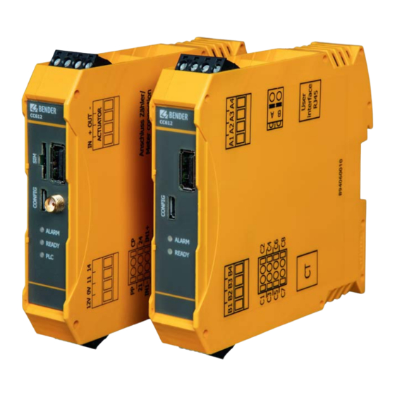
- Page 1 CC612 charge controller Charge controller for electric vehicle charging stations, wallboxes or street light charging points CC612(4G)_D00325_06_M_XXEN/09.2021 Manual EN...
- Page 2 Service and support for Bender products First-level support Technical support Carl-Benz-Strasse 8 • 35305 Grünberg • Germany Telephone: +49 6401 807-760 0700BenderHelp * Fax: +49 6401 807-629 E-mail: support@bender-service.de Available on 365 days from 7.00 a.m. to 8.00 p.m. (MEZ/UTC +1) * Landline German Telekom: Mon-Fri from 9.00 a.m.
-
Page 3: Table Of Contents
Signs and symbols ......................5 Training courses and seminars.................5 Delivery conditions .......................5 Inspection, transport and storage ................6 Warranty and liability....................6 Disposal of Bender devices ..................6 Safety ..........................6 Function ....................7 Intended use ........................7 Product features (depending on the variant) .............7 Product description ......................8 Functional description ....................8... - Page 4 Establishing a network connection to the charge controller ....31 6.1.1 USB configuration interface ................... 31 Technical data .................. 32 Tabular data ......................... 32 Standards, approvals, certifications ..............34 Declaration of conformity ..................35 Ordering details ......................36 Document revision history ..................37 CC612(4G)_D00325_06_M_XXEN/09.2021...
-
Page 5: General Instructions
Training courses and seminars www.bender.de > Know-how-> Seminars. Delivery conditions The conditions of sale and delivery set out by Bender apply. These can be obtained from Bender in printed or electronic format. The following applies to software products: "Softwareklausel zur Überlassung von Standard- Software als Teil von Lieferungen, Ergänzung und Änderung der Allgemeinen Lieferbedingungen für Erzeugnisse und... -
Page 6: Inspection, Transport And Storage
• Non-observance of technical data. • Repairs carried out incorrectly. • Use of accessories and spare parts not recommended by Bender. • Catastrophes caused by external influences and force majeure. • Mounting and installation with device combinations not recommended by the manufacturer. -
Page 7: Function
Function Intended use The CC612 charge controller, hereafter referred to as the charge controller, is the main component of a charg- ing system and is designed for use in electric vehicle (EV) charging stations, wall boxes and street light charg- ing points. -
Page 8: Product Description
With the integrated monitoring of the DC fault current, only an RCD type A is required in the charging system. • Data exchange between the EV and the charging system is possible via ISO 15118 compliant Powerline Communication (PLC). CC612(4G)_D00325_06_M_XXEN/09.2021... - Page 9 CC612 charge controller • If a malfunction occurs, a report is sent to the backend system using the OCPP protocol. • Data management and control functionality of the charge controller: – Termination of the charging process after tripping of the residual current device (RCD) due to a residual current.
-
Page 10: Dimensions And Mounting
Dimensions and mounting Dimensions and mounting Dimensions 22,6 113,65 Abb. 3–1 Note: Dimensions in mm acc. to ISO 2768 - m * Dimensions incl. antenna socket Mounting Click! DIN rail mounting Example view 3.2.1 Charging system with Type 2 socket CC612(4G)_D00325_06_M_XXEN/09.2021... - Page 11 CC612 charge controller Wiring diagram bottom front 12V 0V 11 14 CC612 12 V RJ45 ALARM RJ10 READY – OUT + IN CP PP IN1– IN1+ IN2– IN2+ – – IN1– IN1+ IN2– IN2+ CC612(4G)_D00325_06_M_XXEN/09.2021...
- Page 12 Dimensions and mounting Charge Controller CC612 The SIM card slot and antenna socket are available on Master variants only. Master variants are: CC612-1M4PR CC612-2M4PR CC612-2M4R Relay The relay used to control the contactor is rated for 30 V/1 A. An intermediate relay may be required if this rating is inadequate.
-
Page 13: Charging System With A Type 2 Socket And An Intermediate Relay
CC612 charge controller 3.2.2 Charging system with a type 2 socket and an intermediate relay Wiring diagram bottom front 12V 0V 11 14 CC612 12 V RJ45 ALARM RJ10 READY – OUT + IN CP PP IN1– IN1+ IN2– IN2+ –... - Page 14 Relay 1: Control pin contactor RCD Type A Output relay 2 Voltage supply DC 12V Intermediate relay Current Transformer (CT) with plug Optocoupler input 1 Optocoupler input 2 * Mennekes Typ-2-socket Assignment of the terminals 12 V IN1- IN1+ IN2- IN2+ CC612(4G)_D00325_06_M_XXEN/09.2021...
- Page 15 CC612 charge controller Connection Type 2 Socket Supported Type 2 sockets* Socket actuator wiring • Mennekes (31016, 31023, 31024, 31038) • Bals (801191-801195, 80300, 9743205000, 9743211000) Wire 3 Wire 1 Wire 2 • Walther Werke (9743211000) • Harting Wire 1...
-
Page 16: Connection
• Modbus (A, B) must be connected using a shielded cable; connect shield to PE.. For further information on connection, refer to the manuals of the accessories (e.g. CTBC17). CC612(4G)_D00325_06_M_XXEN/09.2021... -
Page 17: Connectivity
CC612 charge controller Connectivity Charge controller connections for all device variants CC612 CC612 ALARM ALARM READY READY 12V 0V 11 14 IN1- IN1+ IN2- IN2+ Front view Data gateway (with modem) Front view Data gateway (without modem) Bottom Variant with eHz meter Variant with Modbus meter CC612(4G)_D00325_06_M_XXEN/09.2021... -
Page 18: Master/Slave Connection
Ethernet cables or WLAN, but limits the dis- tance of the controllers to a few meters as the maximum length of a USB cable is 5 meters. The DLM Slave configuration web page (e.g. http://192.168.123.123) then offers links to access the Master and the Slave configuration. CC612(4G)_D00325_06_M_XXEN/09.2021... -
Page 19: Micro-Usb Configuration Interface (Config)
CC612 charge controller 4.2.1.1 Micro-USB configuration interface (CONFIG) The USB configuration interface (CONFIG) on the charge controller front panel is connected to a conventional laptop, PC or tablet computer with a normal USB host interface via a micro USB cable. This interface allows the device to be configured locally. -
Page 20: Control Pilot (Cp) And Proximity Pilot (Pp) Connections
4.2.1.7 I/O extension The CC612 has additional I/O interfaces available via a configurable 3-channel I/O interface (connector C: 21, 24, IN1-, IN1+, IN2-, IN2+) that can be used for multiple purposes, for example: • Parking management interface (The supported communication protocol is proprietary to Scheidt &... -
Page 21: Connection To Lock Release Modules
CC612 charge controller 4.2.1.10 Connection to lock release modules When using the Mennekes Actuator Control Type 30537-A, the full force is not available for the locking and unlocking process. The following legend refers to the corresponding connection examples: Connection A of the charge controller... - Page 22 Socket actuator Walther Werke Eco Slim 32 A (9743205180) with Mennekes lock release module: Mennekes Actuator Control Typ 30537-A Socket actuator Walther Werke Eco Slim 32 A (9743205180) with Phoenix Contact lock release module: POWER ERROR EV Charge Lock Release 12V GND +IN -IN +OUT-OUT CC612(4G)_D00325_06_M_XXEN/09.2021...
- Page 23 CC612 charge controller A typical wiring diagram illustrating the connection between the charge controller, a Phoenix Contact socket actuator and a lock release module (EM-EV-CLR-12V) from Phoenix Contact is shown below: POWER ERROR EV Charge Lock Release 12V GND +IN...
-
Page 24: Connectivity To Ehz Or Modbus Meters And (Optionally) Meters With An S0 Interface
Modbus RTU can be used instead of an RS-485 based eHZ interface to connect to Modbus meters. Various Modbus meters are currently supported, see: www.bender.de/en/supported-energy-meters. Additional Modbus meters can be added upon customer request and may be added with each software re- lease. -
Page 25: Sim Card And Sim Card Slot
CC612 charge controller 4.2.2.1 SIM card and SIM card slot • The charge controller supports 4G mobile networks and an integrated modem is included. It uses a wireless module, which supports the following European frequency bands: – LTE FDD: 800 MHz band 20, 900 MHz band 8, 1,800 MHz band 3, 2,100 MHz band 1 and 2,600 MHz band 7 –... -
Page 26: Configuration And Testing
An example of a local configuration Charge Point Control Interface State, Manufacturer and Operator tab is shown on the following pages. Each of the parameters to be set is adequately described on the respective web interface pages. Please refer to these pages for further information: CC612(4G)_D00325_06_M_XXEN/09.2021... -
Page 27: Periodicle Reboot Of The Charge Controller
CC612 charge controller • The State tab of the charging system control interface can be accessed via the URL http://192.168.123.123. It only provides status information. • The Operator tab of the charging system control interface can be accessed via the URL http://192.168.123.123/operator. -
Page 28: Remote Configuration Of Parameters
RFID module (if configured) lights continuously, marking the end of the boot up sequence 5.1.6 Connectivity to the backend 5.1.6.1 Connection of the charge controller to the backend Go to the Settings tab (http://192.168.123.123/operator/settings). To access this tab, enter the following user name and password: • User name: operator • Password: yellow_zone CC612(4G)_D00325_06_M_XXEN/09.2021... -
Page 29: Via Gsm (4G Modem)
CC612 charge controller The following options are available at "Connection Type": • No backend • GSM (4G modem) • Ethernet • USB • WiFi 5.1.6.2 via GSM (4G modem) The "Access Point Name (APN)" of the mobile network to be used is required when a connection to the back- end system is made via the integrated 4G modem. -
Page 30: Ehz/Modbus/S0 Meter Connectivity
• Authorisation AFTER connecting The modes of operation are briefly described in the respective RFID module manual, which can be download- ed from www.bender.de/en/service-support/downloads. The connection to the mobile phone data network and subsequently the backend system usually lasts an- ywhere between 6 and 48 hours. -
Page 31: Connecting To The Charge Controller
CC612 charge controller Connecting to the charge controller The charge controller runs the Linux operating system (OS). The easiest way to connect to the system is to connect through a TCP/IP network connection. This can be done by establishing a network connection. -
Page 32: Technical Data
LED ALARM �������������������������������������������������������������������������������������������������������������������������������������������������������������������������������������yellow LED READY ��������������������������������������������������������������������������������������������������������������������������������������������������������������������������������������� green LED PLC �������������������������������������������������������������������������������������������������������������������������������������������������������������������������������������������� green USB Extension interface (Ethernet, WLAN,���) �������������������������������������������������������������������������������������������������������������� USB socket type A CONFIG (Configuration interface) ���������������������������������������������������������������������������������������������������������������������� Micro USB socket type AB SIM card (For data gateways with 4G modem only) ������������������������������������������������������������������������������������������������������������������micro SIM CC612(4G)_D00325_06_M_XXEN/09.2021... - Page 33 CC612 charge controller Terminal A: IN ������������������������������������������������������������������������������������������������������������������������������������������������������������������������������������������� �Aktuator IN + ���������������������������������������������������������������������������������������������������������������������������������������������������������������������������������������������Aktuator + OUT ����������������������������������������������������������������������������������������������������������������������������������������������������������������������Aktuator pull-up output - ����������������������������������������������������������������������������������������������������������������������������������������������������������������������������������������������� Aktuator - Terminal B: 12V ������������������������������������������������������������������������������������������������������������������������������������������������������������������������������������������� +12 V IN* 0V ���������������������������������������������������������������������������������������������������������������������������������������������������������������������������������������������������� 0 V IN 11 ����������������������������������������������������������������������������������������������������������������������������������������������������������������������������������������������Relay 1 NO 14� ���������������������������������������������������������������������������������������������������������������������������������������������������������������������������������������������Relay 2 NO Terminal C: PP �������������������������������������������������������������������������������������������������������������������������������������������������������������������������������������...
-
Page 34: Standards, Approvals, Certifications
• EN 61851-1: 2011 • EN 301 489-1: V2.2.0 Draft • EN 301 511 V12.5.1 • EN 301 908-13 V11.1.2 • EN 62311: 2008 • EN 61851-22: 2002 • EN 301 489-52 V1.1.0 Draft • EN 301 908-1 V11.1.1 CC612(4G)_D00325_06_M_XXEN/09.2021... -
Page 35: Declaration Of Conformity
Produktbezeichnung: Ladekontroller CC612-4G (siehe Anlage) Product name: Charge Controller CC612-4G (see annex) auf das sich diese Erklärung bezieht, mit den Vorschriften folgender Europäischen Richtlinien übereinstimmt. to which this declaration relates, is in conformity with the following European directives. -
Page 36: Ordering Details
Technical data Ordering details Type Modem Meter RDC-M PLC* User interface Art�-No� Manual- No� CC612 -1M4PR eHZ-, S0- B94060011 D00325 inteface CC612 -2M4PR Modbus, B94060013 D00325 S0-interface Ready, Alarm, PLC CC612 -1S0PR eHZ-, S0-... -
Page 37: Document Revision History
CC612 charge controller Document revision history Date Document Valid from soft- State/Changes version ware version 10/2019 06/2021 Added: Chapter 2�3�1 / Chapter 4�2�1�8: Residual direct current monitoring modulel (RDC-M) Changed: Content to IEC 62955, new layout, all graphics Deleted: Chapter 6�2 Register card State Chapter 6�3 Register card Settings... - Page 38 CC612(4G)_D00325_06_M_XXEN/09.2021...
- Page 39 CC612 charge controller CC612(4G)_D00325_06_M_XXEN/09.2021...
- Page 40 Nachdruck und Vervielfältigung Reprinting and duplicating nur mit Genehmigung des Herausgebers. only with permission of the publisher. Bender GmbH & Co. KG Bender GmbH & Co. KG Postfach 1161 • 35301 Grünberg • Deutschland PO Box 1161 • 35301 Grünberg • Germany Londorfer Str.
Need help?
Do you have a question about the CC612 and is the answer not in the manual?
Questions and answers