
Related Manuals for Bender CC613


Summary of Contents for Bender CC613
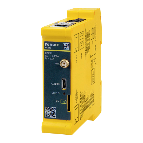
- Page 1 CC613 charge controller Charge controller for use in electric vehicle charging stations, wallboxes or street light charging points CC613_D00381_04_M_XXEN/11.2020 Manual EN...
- Page 2 Service and support for Bender products First-level support Technical support Carl-Benz-Strasse 8 • 35305 Grünberg • Germany Telephone: +49 6401 807-760 0700BenderHelp * Fax: +49 6401 807-629 E-mail: support@bender-service.de Available on 365 days from 7.00 a.m. to 8.00 p.m. (MEZ/UTC +1) * Landline German Telekom: Mon-Fri from 9.00 a.m.
-
Page 3: Table Of Contents
Signs and symbols ......................5 Training courses and seminars.................5 Delivery conditions .......................5 Inspection, transport and storage ................6 Warranty and liability....................6 Disposal of Bender devices ..................6 Safety ..........................6 Function ....................7 Intended use ........................7 Product features (depending on the variant) .............7 Product description ......................8 Functional description ....................8... - Page 4 4.3.11 I/O extension ........................ 17 4.3.12 Emergency opener ....................17 4.3.13 Residual direct current monitoring module (RDC-M)........17 4.3.14 Connectivity with Modbus meters ..............18 4.3.15 Gateway variants with modem ................18 4.3.16 Antenna socket ......................19 Configuration and testing ............. 20 Configuration .......................
-
Page 5: General Instructions
Training courses and seminars www.bender.de > Know-how-> Seminars. Delivery conditions The conditions of sale and delivery set out by Bender apply. These can be obtained from Bender in printed or electronic format. The following applies to software products: "Softwareklausel zur Überlassung von Standard- Software als Teil von Lieferungen, Ergänzung und Änderung der Allgemeinen Lieferbedingungen für Erzeugnisse und... -
Page 6: Inspection, Transport And Storage
• Non-observance of technical data. • Repairs carried out incorrectly. • Use of accessories and spare parts not recommended by Bender. • Catastrophes caused by external influences and force majeure. • Mounting and installation with device combinations not recommended by the manufacturer. -
Page 7: Function
The default passwords should be changed to prevent unauthorised access. Intended use The CC613 charge controller, hereinafter referred to as "charge controller", is the main component of a charg- ing system. It is intended for use in electric vehicle charging stations, wallboxes or street light charging points. -
Page 8: Product Description
Function Product description The charge controller monitors the internal hardware of charging systems such as the meter, the user inter- face module or the socket-outlet. It can be operated as an "always-on system" that is always connected to a mobile network. The master variant supports 4G mobile networks. Communication with a backend system is possible via the OCPP application protocol. -
Page 9: Load Current And Cooling Control (Temperature Monitoring)
CC613 charge controller The charge controller with residual direct current monitoring module (RDC-M) only works in combination with the measuring current transformer (to be ordered separately). ! Risk of damage when pulling out the measuring current aution transformer plug! If the measuring current transformer plug is pulled out using too much force, the enclosure and the internal components may be damaged. -
Page 10: Dimensions And Mounting
Dimensions and mounting Dimensions and mounting Dimensions 111 (112,3*) 23,5 Abb. 3–1 Note: Dimensions in mm acc. to ISO 2768 - m * Dimensions incl. antenna socket Mounting Click! DIN rail mounting Lateral distance to other equipment: 6 mm (self-heating) In horizontal mounting position, the max. -
Page 11: Connection
CC613 charge controller Connection Connection conditions of electric shock! Parts of the system may be live (charge controller terminals up to 230 V, charging station 400 V). Before touching parts of the system, ensure that it has been de-energised. ! Risk of injury from sharp-edged terminals! Handle enclosure and terminals with care. -
Page 12: Charging System With Type 2 Socket-Outlet
Connection 4.2.2 Charging system with type 2 socket-outlet Wiring diagram front bottom 12 V Side view from right GND2 B Mod. A Mod. +12V – CC613_D00381_04_M_XXEN/11.2020... - Page 13 STATUS LED ¹ Data gateways with 4G modem: CC613-ELM4PR and CC613-ELM4R The external Modbus (terminal I) is only used for remote control of the CC613 via an energy management system and is not intended for connecting a meter. Terminal assignment...
-
Page 14: Connection Locking Actuators
Connection 4.2.3 Connection locking actuators Type 2 socket-outlet (actuator type) Actua- Socket-outlet actuator wiring • Mennekes (31016, 31023, 31024, 31038) • Bals (801191-801195, 80300, 9743205000, Wire 3 Wire 1 Wire 2 9743211000) (///) (//) • Walther Werke (9743211000) Hella • Harting •... -
Page 15: Master/Slave Connection
CC613 charge controller 4.3.1 Master/slave connection The charge controller serves as a data gateway. Master/slave operation requires the USB configuration inter- face (micro USB 2.0, master) to be connected to the USB type A interface (slave) via a USB cable. The master becomes the OCPP backend for the slave. -
Page 16: Weld Check
Connection 4.3.7 Weld check By means of the measuring lines WA/WB (terminal designation) an impermissible closing of the contactor contacts, e.g. welding/sticking, can be detected. Wiring diagram of a short circuit! According to DIN VDE 0100-430, devices for protection against a short circuit can be omitted for the coupling of terminals WA and WB if the wiring is carried out in such a manner as to reduce the risk of a short circuit to a minimum. -
Page 17: Pe Monitoring
4.3.9 PE monitoring The PE monitoring checks whether there is a connection from the CC613 to PE. For this purpose, WA must be connected to L1. The cable length is limited by its capacitance per unit length. Pe monitoring does not replace tests (example: protective conductor resistance). -
Page 18: Connectivity With Modbus Meters
Connection 4.3.14 Connectivity with Modbus meters The use of a meter is not mandatory. It is necessary if measured values are required during normal operation. The meter is connected to the Modbus meter interface (terminal B) of the charge controller. Various Modbus meters are currently supported, including: •... -
Page 19: Antenna Socket
CC613 charge controller 4.3.16 Antenna socket The antenna socket allows connection to a 4G antenna (not included in the scope of delivery). The following approved antenna type must be used: PSI-GSM/UMTS-QB-ANT. CC613_D00381_04_M_XXEN/11.2020... -
Page 20: Configuration And Testing
Configuration and testing Configuration and testing Configuration The following options are available for configuring the charging system: Access to web interface via the following interfaces: • Micro USB configuration interface (CONFIG) • Ethernet interface • 4G modem • Remote access - the ChangeConfiguration command of the OCPP protocol is used (depends on the backend system). -
Page 21: Remote Configuration Of Parameters
CC613 charge controller The Operator tab of the charging system control interface can be accessed via the URL http://192.168.123.123/ operator. To access this tab, user name and password are required: • User name: operator • Password: yellow_zone The Manufacturer tab of the charging system control interface can be accessed via the URL http://192.168.123.123/manufacturer. -
Page 22: Factory Settings
Configuration and testing 5.1.3 Factory settings Resetting to factory settings deletes all settings except the serial number. Click the "Operator Default & Restart" button on the Operator tab to reset changed parameters of the operator configuration to default. Click the "Settings Default & Restart" button on the Settings tab to reset changed parameters to default. -
Page 23: Plug Locking And Unlocking
CC613 charge controller GSM (4G modem) The "Access Point Name (APN)" of the mobile network to be used is required when a connection to the back- end system is made via the integrated 4G modem. A user name ("APN Username") and password ("APN Password") may be required to authenticate the access point. -
Page 24: Authorisation And Charging
RFID module, the contactor is switched on and a current flow takes place. The charge controller enables two modes of operation: • Authorisation BEFORE connecting • Authorisation AFTER connecting The modes of operation are briefly described in the respective RFID module manual, which can be download- ed from www.bender.de/en/service-support/downloads. CC613_D00381_04_M_XXEN/11.2020... -
Page 25: Technical Data
CC613 charge controller Technical data Tabular data Insulation coordination acc. to IEC 60664-1/IEC 60664-3 Rated voltage ....................................250 V Overvoltage category ............................. II (within terminal H) Overvoltage category ........................III (terminal H and all other terminals) Rated impulse voltage ......................6 kV (terminal H and all other terminals) Rated impulse voltage ............................. - Page 26 Technical data LED indications STATUS (front plate) ....................orange: power on/system not ready for operation ....................................blue: system is starting ............................green: system started, not ready for operation yet ........................flashing green: system running, system ready for operation ......................................red: system error Ethernet (terminal D) ............................. off: no Ethernet connection .............................
- Page 27 CC613 charge controller Classification of climatic conditions acc. to IEC 60721: Stationary use (IEC 60721-3-3)..................3K23 (except condensation and formation of ice) Transport (IEC 60721-3-2) .................................2K11 Long-term storage (IEC 60721-3-1) ..............................1K21 Classification of mechanical conditions acc. to IEC 60721: Stationary use (IEC 60721-3-3) .................................3M11 Transport (IEC 60721-3-2) .................................
-
Page 28: Declaration Of Conformity
Produktbezeichnung: Ladekontroller CC613-ELM4PR-M (siehe Anlage) Product name: Charge Controller CC613-ELM4PR-M (see annex) auf das sich diese Erklärung bezieht, mit den Vorschriften folgender Europäischen Richtlinien übereinstimmt. to which this declaration relates, is in conformity with the following European directives. -
Page 29: Ordering Details
CC613 charge controller Ordering details Type Modem Inter- RDC-M External PLC* User Art� No� Manual face Modbus interface No� CC613-ELM4PR-M B94060020 D00381 CC613-ELPR-M B94060021 D00381 Modbus, STATUS Ethernet CC613-ELM4PR B94060026 D00381 ... -
Page 30: Document Revision History
Technical data Document revision history Date Document Valid State/Changes version from software version 10/2020 Added: Chapter 2: Local access charge controller Chapter 4.1: Ext. Modbus terminating resistor Chapter 4.2.2: Wiring diagram side view from right Chapter 4.2.2: Info on terminal I remote control Chapter 4.2.3: in table: Walther Werke Eco Slim 32 A Chapter 4.2.3: Connection Phoenix Contact (Küster) Chapter 4.3.14: Connection info terminal B... - Page 31 CC613 charge controller CC613_D00381_04_M_XXEN/11.2020...
- Page 32 Nachdruck und Vervielfältigung Reprinting and duplicating nur mit Genehmigung des Herausgebers. only with permission of the publisher. Bender GmbH & Co. KG Bender GmbH & Co. KG Postfach 1161 • 35301 Grünberg • Deutschland PO Box 1161 • 35301 Grünberg • Germany Londorfer Str.
Need help?
Do you have a question about the CC613 and is the answer not in the manual?
Questions and answers