
Subscribe to Our Youtube Channel
Related Manuals for Bender CC612


Summary of Contents for Bender CC612
- Page 1 Manual CC612 EV charge controller Charge controller for electric vehicle charging stations, wall boxes and street light charging points CC612(4G)_D00325_04_M_XXEN/03.2019...
- Page 2 E-Mail: info@bender.de Web: www.bender.de Customer service Service-Hotline: 0700-BenderHelp (Phone and Fax) Carl-Benz-Straße 8 • 35305 Grünberg • Germany © Bender GmbH & Co. KG Tel.:+49 6401 807-760 All rights reserved Fax:+49 6401 807-629 Reprint only with permission of the manufacturer E-Mail:info@bender-service.com...
-
Page 3: Table Of Contents
4.2 DIN rail mounting ..........14 CC612(4G)_D00325_04_M_XXEN/03.2019... - Page 4 8.4 Ordering information* ..........44 Index ....................... 45 CC612(4G)_D00325_04_M_XXEN/03.2019...
-
Page 5: Important Information
This manual has been compiled with great care. It might nevertheless contain errors and Londorfer Str. 65, mistakes. Bender cannot accept any liability for injury to persons or damage to property 35305 Gruenberg resulting from errors or mistakes in this manual. -
Page 6: Field Service
Electronic Manufacturer's Association) also applies. • Electrical and electronic equipment are not part of household waste. Sale and delivery conditions can be obtained from Bender in printed or electronic format. • Batteries and accumulators are not part of household waste and must be disposed 1.5 Inspection, transport and storage... -
Page 7: Safety Information
Risk of fatal injury from electric shock! The CC612 charge controller, hereafter referred to as the charge controller, is the main Touching live parts of the system carries the risk of: component of a charging system and is designed for use in electric vehicle (EV) charging •... -
Page 8: Function
• A Peer Group Mechanism or Dynamic Load Management where a set current is shared between a group of charge controllers • Optional integrated ISO/IEC 15118 power line communication (PLC) for plug & charge and load management systems • Local and remote configuration CC612(4G)_D00325_04_M_XXEN/03.2019... -
Page 9: Product Variant Overview
(EMH eHZ) or a digital Modbus meter is required. eHZ and S0 Ready, CC612 -1M4PR interface Alarm, PLC • The charge controller reads the digital eHZ meter readings using a standard opti- cal reader attached to the charge controller via an RJ10 plug. Modbus, S0 Ready, ... - Page 10 USB device ports, it is necessary to assign individual IP addresses to these control- • Remote restart after a residual current trip that is recognized by the CC612. lers to enable TCP/IP connectivity between both. This is possible using the confi- guration parameters "USB additional fixed IP"...
-
Page 11: Way Of Connecting With Type 2 Socket
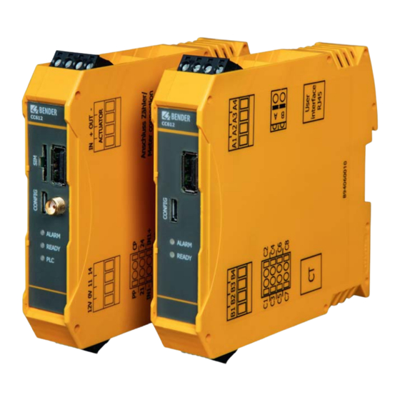
Function Function 3.3.2 Way of connecting with Type 2 socket Charge Controller CC612 The SIM card slot and antenna socket are available on Master variants only. Master variants are: CC612-1M4PR CC612-2M4PR CC612-2M4R CC612 Charge Controller PLC is optional. Relay Bottom view... -
Page 12: Charging System With A Type 2 Socket And An Intermediate Relay
Type 2 plug* D Connection Current Transformer (CT) Connection Proximity Pilot E Terminal User Interface (RJ45) Connection Control Pilot CC612 Charge Controller F Terminal Modbus/eHZ meter (RJ10) Relay 1: Control pin intermediate relay RCD Type A Output relay 2 Bottom view... - Page 13 BU/BN BE/GN BU/RD BU/YE 1408171, 1408172) * Each type 2 socket can also be used in conjunction with lock release modules from Mennekes and Phoenix Contact. Connection to Type 1/Type 2 plug L2/N Type 2 plug Type 1 plug CC612(4G)_D00325_04_M_XXEN/03.2019...
-
Page 14: Device Overview
Fix the charge controller onto the DIN rail by pulling down the silver-coloured mounting clip (indicated in photos below). Position the charge controller and release the clip to allow the device to sit securely on the rail. 115.13 22.60 CC612 ALARM READY Mounting clip... -
Page 15: Connection
• Cable lengths (except Modbus, Power IN and charging cable) < 3 m; cables must be positioned inside the wallbox/charging station and should not be laid parallel to power cables. • Modbus (A, B) must be connected using a shielded cable; connect shield to PE. CC612(4G)_D00325_04_M_XXEN/03.2019... -
Page 16: Connectivity
Data gateway (with modem) Data gateway (without modem) Configuration interface/connection to Slave LEDs for: • ALARM • READY (Online connectivity) CC612 CC612 • PLC (Power Line Communication) - Optional 12 V power supply Relay 1 (Control voltage contactor) Relay 1 (Contactor control pin) -
Page 17: Master/Slave Connections
WLAN of the second charge controller (DLM Slave) using a USB cable. pole (0 V) of the power source. The contactor control pin is then connected to the supply voltage (e.g. 230 V) and the other pin is connected to the neutral conductor. CC612(4G)_D00325_04_M_XXEN/03.2019... -
Page 18: Control Pilot (Cp) And Proximity Pilot (Pp) Connections
RDC-MD which works with an external magnetically shielded me- asuring current transformer (CT) connected to the CC612. This allows the use of a type A RCD in the charging system instead of the more expensive type B RCD. The relay in the CC612 triggers if, during charging, the fault current limit I ≥... -
Page 19: Connection To Lock Release Modules
Mennekes/Bals/Walther Werke/Harting socket actuator and a lock release module (EM-EV-CLR-12V) from Phoenix Contact is shown below: Mennekes/Bals/Walther Werke/Harting Type 2 socket POWER ERROR EV Charge Lock Release To CC612 connector A -IN +OUT-OUT Wire 3 IN + OUT - Wire 1 Wire 2... - Page 20 Connection Mennekes Actuator Control Walther Werke Eco Slim 32 A (9743205180) Typ 30537-A Type 2 socket To CC612 connector A Wire 1 IN + OUT - Wire 3 Wire 2 CC612(4G)_D00325_04_M_XXEN/03.2019...
- Page 21 Connection Walther Werke Eco Slim 32 A (9743205180) Type 2 socket POWER ERROR EV Charge Lock Release To CC612 -IN +OUT-OUT connector A Wire 1 IN + OUT - Wire 3 Wire 2 CC612(4G)_D00325_04_M_XXEN/03.2019...
- Page 22 A typical wiring diagram illustrating the connection between the charge controller, a Phoenix Contact socket actuator and a lock release module (EM-EV-CLR-12V) from Phoenix Contact is shown below: Phoenix Contact (Kuester) Type 2 socket POWER ERROR EV Charge Lock Release To CC612 connector A -IN +OUT-OUT BU/YE IN + OUT - BU/BN BU/RD BU/GN...
- Page 23 A typical wiring diagram illustrating the connection between the charge controller, a Mennekes socket actuator and a lock release module from Mennekes is shown below: Mennekes Actuator Control Typ 30537-A Mennekes/Bals/Walther Werke/Harting Type 2 socket To CC612 connector A Wire 3 IN + OUT - Wire1 Wire 2 CC612(4G)_D00325_04_M_XXEN/03.2019...
-
Page 24: Connectivity To Ehz Or Modbus Meters And (Optionally) Meters With An S0 Interface
LEDs and is designed according to ISO14443A/MIFARE. It is connected to the charge controller using a standard RJ45 cable. The RFID module is described in a separate operating manual (docu- ment number D00328), which can be downloaded from www.bender.de/en/service-support/downloads. CC612(4G)_D00325_04_M_XXEN/03.2019... -
Page 25: Master Device Features
Connection to the mobile network (and subsequently the backend system) usually lasts The antenna is not included within the scope of delivery. between 6 to 48 hours after which the connection may be terminated by the mobile net- CC612(4G)_D00325_04_M_XXEN/03.2019... -
Page 26: Configuration And Testing
Operator tab is shown on the following pages. Each of the parameters to be set is adequately described on the respective web interface pages. Please refer to these pages for further information: • The Charging System Control Interface State tab is accessed using the URL http://192.168.123.123 and shows status information only. CC612(4G)_D00325_04_M_XXEN/03.2019... -
Page 27: Application Of Changed Parameters
To reset all changed parameters to default on the Settings tab, click the parameters using the OCPP GetConfiguration and ChangeConfiguration commands. "Settings Default & Restart" button at the bottom of the tab. With these commands, locally configured communication parameters can be changed. CC612(4G)_D00325_04_M_XXEN/03.2019... -
Page 28: State Tab
The type of meter used for the charging socket will be shown. and its connector. This is relevant for OCPP Meter configuration (OCPP) The name of the network operator the built-in Currently used 3G Network opera- transactions. 4G modem is currently connected to. CC612(4G)_D00325_04_M_XXEN/03.2019... - Page 29 Use option "On" while vehicle connected for integration with parking HMI Pattern On Relay 2 (K2) management system by Scheidt & Bachmann. To use two contactors in series that are to be controlled separately, use the function "ON while charging". CC612(4G)_D00325_04_M_XXEN/03.2019...
-
Page 30: Settings Tab
APN for remote messages to arrive at the group configured. charge point. Also Binary OCPP uses much less data (factor 20 to 50) than standard OCPP. Binary OCPP however requires a Binary OCPP proxy on the backend side. CC612(4G)_D00325_04_M_XXEN/03.2019... -
Page 31: Operator Tab
USB network without IP conflicts. The subnet mask charge point. "Auto" uses DHCP to configure the charge Mode for network is fixed at 24 bits 255.255.255.0. point‘s network connection; "Manual config" uses the configuration addresses as filled in above. CC612(4G)_D00325_04_M_XXEN/03.2019... - Page 32 Some backends are upset if StatusNotification state "Occupied on Authorized/Plugged", the state changes this is done. transitions to "Occupied already" when the charger is authorized with nothing connected or when a cable/vehicle is connected, but no authorization has taken place yet. CC612(4G)_D00325_04_M_XXEN/03.2019...
- Page 33 Set "0" to turn off or to a value ≥ 60 to turn on. Overall current limit for DLM on phase 1 in Ampere (A). Overall current limit for DLM This setting is only used on the DLM Master. on Phase 1 CC612(4G)_D00325_04_M_XXEN/03.2019...
- Page 34 Volts. This is used for current Power source voltage calculation from power values from meter. Welded contactor detection Welded contactor detection (Always enabled in CC612) This parameter describes how many and which phases Phases connected to the...
-
Page 35: Manufacturer Tab
ChargePoint. Please note that the default value Pilot line is connected or not. ChargePoint Model "CC612" is reserved and cannot be used on non- Set to "On" if a hatch is installed in the charge CC612 models. point. Note that this parameter is relevant only... -
Page 36: Testing
It must be "Off" when there is no MCB connected web interface. This password is set as root access Manufacturer Password MCB Enable to the controller. In CC612 the opto input C8/7 is for the charge point. used. 6.6 Testing This parameter allows to enable RCD detection. -
Page 37: Successful Boot-Up
• To unlock the plug, first disconnect the plug from the vehicle. This action automati- be possible. With a data network connection established, the charging system is now cally unlocks the charging system socket, allowing the cable to be removed. available. CC612(4G)_D00325_04_M_XXEN/03.2019... -
Page 38: Unlocking The Ct Plug
The vehicle is not connected to the charging system within 45 seconds. Alter- • If the RFID110-L1 module is installed, the display changes to indi- native cate that the charging system is „Free“ and the green LED lights step 3 continuously. CC612(4G)_D00325_04_M_XXEN/03.2019... - Page 39 The charging system detects this disconnection and automati- cally reconnects. During the reconnect, all three LEDs on the charge cont- roller front panel flash frequently. CC612(4G)_D00325_04_M_XXEN/03.2019...
-
Page 40: Connecting To The Charge Controller
IP address to the host machine once it is connected. Therefore, commu- nication with the charge controller is based on this IP address. The charge controller must be powered with 12 V when the CONFIG inter- face is being used. CC612(4G)_D00325_04_M_XXEN/03.2019... -
Page 41: Technical Data
Minimum contact rating ............................. 1 mA ≥ 10 V USB Extension interface (Ethernet, WLAN, …) ..................USB socket type A Rated voltage ..................................32 V CONFIG (Configuration interface) ......................Micro socket type AB SIM card (For data gateways with 4G modem only) ....................micro SIM CC612(4G)_D00325_04_M_XXEN/03.2019... -
Page 42: Standards, Approvals, Certifications
Stripping length................................7 mm Other Operating mode............................continuous operation Degree of protection................................. IP20 DIN rail mounting ..............................IEC 60715 Weight ....................................160 g *) Surge test is carried out at Phoenix power supply STEP-PS/1AC/12DC/1.5. The 12V cable length is less than1 meter. CC612(4G)_D00325_04_M_XXEN/03.2019... -
Page 43: Declaration Of Conformity
EU - K o n f o r m i t ä t s e r k l ä r u n g Anlage - Typenliste der EU-Konformitätserklärung CC612-G4 E U - D e c l a r a t i o n o f C o n f o r m i t y... -
Page 44: Ordering Information
Technical Data Technical Data 8.4 Ordering information* RDC- PLC** User Type Modem Meter LEDs Art. No. hardware interface Ready eHZ, S0 B94060011 CC612 -1M4PR Alarm interface Ready Modbus, S0 CC612 -2M4PR Alarm B94060013 interface Ready... -
Page 45: Index
USB devices 9 Fault monitoring 10 Product description 8 Ethernet/WLAN adapter 17 current transformer 10 Proximity Contact (PP) 18 residual current monitoring (RCM) 10 features 8 Function 8 RFID module 24 RJ10 plug 9 Functional description 9 RJ45 cable 9 CC612(4G)_D00325_04_M_XXEN/03.2019... - Page 48 Bender GmbH & Co. KG Customer service Postbox 1161 • 35301 Grünberg • Germany Service hotline: 0700-BenderHelp (Telephone and Fax) Londorfer Straße 65 • 35305 Grünberg • Germany Carl-Benz-Straße 8 • 35305 Gruenberg • Germany Tel.: +49 6401 807-0 Tel.:...
Need help?
Do you have a question about the CC612 and is the answer not in the manual?
Questions and answers