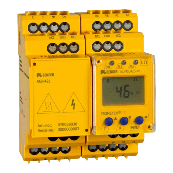
Bender ISOMETER isoMIL425HV Manual
Insulation monitoring device with coupling device agh421 for unearthed ac, ac/dc and dc systems for military applications up to 3(n)ac, ac 690 v, dc 1000 v software version: d460 v1.xx
Hide thumbs
Also See for ISOMETER isoMIL425HV:
- Manual (33 pages) ,
- Manual (71 pages) ,
- Quick start manual (12 pages)
Table of Contents
Advertisement
Quick Links
Advertisement
Table of Contents

Related Manuals for Bender ISOMETER isoMIL425HV


Summary of Contents for Bender ISOMETER isoMIL425HV
- Page 1 Manual EN ISOMETER® isoMIL425HV Insulation monitoring device with coupling device AGH421 for unearthed AC, AC/DC and DC systems for military applications up to 3(N)AC, AC 690 V, DC 1000 V Software version: D460 V1.xx isoMIL425HV_D00204_06_M_XXEN/08.2023...
- Page 2 isoMIL425HV_D00204_06_M_XXEN/08.2023...
-
Page 3: Table Of Contents
Indication of important instructions and information...............5 Signs and symbols............................5 Service and Support............................5 Training courses and seminars........................6 Delivery conditions............................6 Inspection, transport and storage......................6 Warranty and liability.............................6 Disposal of Bender devices..........................7 1.10 Safety..................................7 Function.......................8 Intended use..............................8 Device features..............................8 Functional description........................... 9 2.3.1... - Page 4 Table of contents Menu overview...............................21 Displaying measured values........................22 Setting the response values (AL)......................23 4.4.1 Setting the response values for insulation monitoring..............23 4.4.2 Setting the response values for undervoltage and overvoltage..........23 4.4.3 Response values overview.........................23 Configuring fault memory, alarm relays, and interfaces (out)............23 4.5.1 Configuring the relays..........................24 4.5.2...
-
Page 5: General Information
Protect from dust Temperature range Recycling RoHS directives Service and Support Information and contact details about customer service, repair service or field service for Bender devices are available on the following website: Fast assistance | Bender GmbH & Co. KG. isoMIL425HV_D00204_06_M_XXEN/08.2023... -
Page 6: Training Courses And Seminars
Regular face-to-face or online seminars for customers and other interested parties: www.bender.de > know-how > seminars. Delivery conditions The conditions of sale and delivery set out by Bender GmbH & Co. KG apply. These can be obtained in printed or electronic format. The following applies to software products: ‘Software clause in respect of the licensing of standard software as part of deliveries,... -
Page 7: Disposal Of Bender Devices
ISOMETER® isoMIL425HV Disposal of Bender devices Abide by the national regulations and laws governing the disposal of this device. For more information on the disposal of Bender devices, refer to www.bender.de > service & support. 1.10 Safety If the device is used outside the Federal Republic of Germany, the applicable local standards and regulations must be complied with. -
Page 8: Function
• Two separately adjustable response value ranges from 1…500 k (prewarning, alarm) • RS-485 (galvanically isolated) including the following protocols: – BMS (Bender measuring device interface) for the data exchange with other Bender devices – Modbus RTU – IsoData (for continuous data output) •... -
Page 9: Functional Description
ISOMETER® isoMIL425HV Functional description The ISOMETER® measures the insulation resistance R and the system leakage capacitance C between the system to be monitored (L1/+, L2/–) and earth (PE). The RMS value of the nominal system voltage U between L1/+ and L2/– as well as the residual voltages U (between L1/+ and earth) and U (between L2/–... -
Page 10: Monitoring The Insulation Resistance
Function 2.3.1 Monitoring the insulation resistance The insulation resistance R is monitored by means of the parameters 'R1' (prewarning) and 'R2' (alarm) (see chapter 4.4). The value 'R1' can only be set higher than the value 'R2'. If the insulation resistance R reaches or falls below the activated values 'R1' or 'R2', an alarm message is triggered. -
Page 11: Malfunction
('err') will be signalled, 'E.xx' appears on the display as an identifier for error type xx, and the LEDs 'ON'/'AL1'/'AL2' will flash. Please contact Bender Service, if the error occurs again after the device has been restarted or the factory settings have been restored. -
Page 12: Alarm Assignment Of The Alarm Relays K1/K2
Function 2.3.5 Alarm assignment of the alarm relays K1/K2 The notifications for 'device error', 'insulation fault', 'undervoltage/overvoltage fault', 'device test' and 'device start with alarm' can be assigned to the alarm relays via the 'out' menu. An insulation fault is indicated by these messages: •... -
Page 13: External Stop Switch
The ISOMETER® uses the serial hardware interface RS-485 with the following protocols: • BMS The BMS protocol is an essential component of the Bender measuring device interface (BMS bus protocol). Data transmission generally makes use of ASCII characters. • Modbus RTU Modbus RTU is an application layer messaging protocol, and it provides master/slave communication between devices that are connected via bus systems and networks. - Page 14 Function With 'Adr = 0', the menu entries baud rate and parity are not shown in the menu and the IsoData protocol is activated. With a valid bus address (i.e. not equal to 0), the menu item 'baud rate' is displayed in the menu. The parameter value '---' for the baud rate indicates the activated BMS protocol.
-
Page 15: Installation, Connection And Commissioning
ISOMETER® isoMIL425HV Installation, connection and commissioning Dimensions 45 70.5 31.1 47.5 74.5 Figure: Dimension diagram (in mm) Installation CAUTION Property damage due to heat When operating on system voltages U > 800 V, the housing of the AGH can become hotter than 60 °C. •... -
Page 16: Connection
Installation, connection and commissioning Connection CAUTION Danger from touching hot surfaces! If the AGH is operated at mains voltages > 800 V, the temperature of the enclosure may exceed 60 °C. • Do not touch the surfaces of the device after connecting it to the mains voltage. CAUTION Only one ISOMETER®... - Page 17 ISOMETER® isoMIL425HV Wiring diagram Figure: Wiring diagram isoMIL425HV_D00204_06_M_XXEN/08.2023...
-
Page 18: Commissioning
Installation, connection and commissioning Commissioning Check that the ISOMETER® is properly connected to the system to be monitored. Connect supply voltage U to the ISOMETER®. The device carries out a calibration, a self test and adjusts itself to the IT system to be monitored. With high system leakage capacitances this process may take up to 4 min. -
Page 19: Operation
ISOMETER® isoMIL425HV Operation Operating and display elements Device front Operating elements Function Device is running Prewarning Overvoltage Alarm Undervoltage Up and down buttons – For navigating up or down in the menu settings. – For increasing or decreasing values. Test button (press > 1.5 s) Reset button (press >... - Page 20 Operation Display Display elements Function System voltage U Insulation resistance R System leakage capacitance C Monitored conductors L1 L2 Voltage type DC Pulse symbol: error-free measured value update Voltage type AC °C Measured values and units μ n F Hz k M Ω...
-
Page 21: Menu Overview
ISOMETER® isoMIL425HV Menu overview Measurement display Menu selection Parameter selection Menu item Parameter Querying and setting response values Configuring fault memory, alarm relays and interface Setting delay times and self test cycles Setting device control parameters Querying software version Querying and clearing the history memory Going to the next-higher menu level isoMIL425HV_D00204_06_M_XXEN/08.2023... -
Page 22: Displaying Measured Values
Operation Displaying measured values Overview Display Description Insulation resistance R ✓ ± R k 1 k … 5 M System leakage capacitance C ✓ C µF 1 µF … 700 µF Nominal system voltage U (L1 - L2) ✓ ~ ± U L1 L2 V …1.2 kV Residual voltage U (L1/+ - PE) -
Page 23: Setting The Response Values (Al)
ISOMETER® isoMIL425HV Setting the response values (AL) 4.4.1 Setting the response values for insulation monitoring How to proceed Open menu 'AL'. Select parameter 'R1' for prewarning or parameter 'R2' for alarm. Set value and confirm with Enter. 4.4.2 Setting the response values for undervoltage and overvoltage How to proceed Open menu 'AL'. -
Page 24: Configuring The Relays
Operation 4.5.1 Configuring the relays Relay K1 Relay K2 Description Display Display Relay operating n.o. n.o. mode n.c./n.o. FAC Factory settings Customer settings 4.5.2 Assigning the alarm messages to the relays The 'on' setting assigns an alarm message to the respective relay. The LED indication is directly assigned to the alarm message and is not related to the relays. -
Page 25: Activating Or Deactivating Fault Memory
ISOMETER® isoMIL425HV 4.5.3 Activating or deactivating fault memory Display Description Memory function for alarm messages (fault memory) FAC Factory settings Customer settings 4.5.4 Configuring interface Display Setting value Description Range Adr = 0 deactivates BMS as well as Modbus 0/3…90 Bus Adr. -
Page 26: Setting Device Control Parameters (Set)
0. . .999 Password for parameter setting System connection test Restore factory settings For Bender Service only FAC Factory settings Customer settings Reset to factory settings All settings with the exception of the interface parameters are reset to the factory settings. -
Page 27: Data Access Via Rs-485 Interface
ISOMETER® isoMIL425HV Data access via RS-485 interface Data access using the BMS protocol The BMS protocol is an essential component of the Bender measuring device interface (BMS bus protocol). Data transmission generally makes use of ASCII characters. BMS channel no. -
Page 28: Writing The Modbus Register (Parameter Setting)
Data access via RS-485 interface Command of the master to the ISOMETER® In the following example, the master of the ISOMETER® requests the content of register 1003 using address 3. The register contains the channel description of measuring channel 1. Byte Name Example... -
Page 29: Exception Code
ISOMETER® isoMIL425HV Response of the ISOMETER® to the master Byte Name Example Byte 0 ISOMETER® Modbus address 0x03 Byte 1 Function code 0x10 Byte 2, 3 Start register 0x0BBB Byte 4, 5 Number of registers 0x0001 Byte 6, 7 CRC16 checksum 0x722A 5.2.3 Exception code... -
Page 30: Modbus Register Assignment
Data access via RS-485 interface Modbus register assignment 5.3.1 Modbus measured value registers Depending on the device condition, the information in the registers is the measured value without alarm, the measured value with alarm 1, the measured value with alarm 2, or the device error. For more information see , page 31. - Page 31 ISOMETER® isoMIL425HV 5.3.1.2 Float = Floating point value of the channels Representation of the bit order for processing analogue measured values according to IEEE 754 Word 0x00 0x01 Byte HiByte LoByte HiByte LoByte 31 30 29 28 27 26 25 24 23 22 21 20 19 18 17 16 15 14 13 12 11 10 exponent mantissa sign...
- Page 32 Data access via RS-485 interface 5.3.1.4 R&U = Range and unit Meaning Unit Invalid (init) No unit Baud °C °F Second Minute Hour Month Range of validity Actual value The actual value is lower The actual value is higher Invalid value •...
-
Page 33: Modbus Parameter Register
ISOMETER® isoMIL425HV 5.3.1.5 Channel descriptions Value Description of measured value / message Comments 1 (0x01) Insulation fault 71 (0x47) Insulation fault Insulation resistance R 76 (0x4C) Voltage Measured value in V 77 (0x4D) Undervoltage 78 (0x4E) Overvoltage 82 (0x52) Capacitance Measured value in F 86 (0x56) Insulation fault... - Page 34 Data access via RS-485 interface Register Property Description Format Unit Value range Activation alarm value overvoltage 'U >' 0 = off 3010 UINT 16 1 = on 3011 Alarm value overvoltage 'U >' UINT 16 U < … 1150 Memory function for alarm 0 = off 3012 UINT 16...
- Page 35 ISOMETER® isoMIL425HV Register Property Description Format Unit Value range 3028 Alarm assignment of relay K2 'r2' UINT 16 Bit 8 … Bit 1 8003 Factory settings for all parameters UINT 16 0x6661 'fa' Factory setting only for 8004 UINT 16 0x4653 'FS' parameters resettable by FAC 8005...
- Page 36 Data access via RS-485 interface Display indication Meaning When reading: 0; Reserved When writing: any value When reading: 0; Reserved When writing: any value When reading: 0 Reserved When writing: any value When reading: 0; 12…15 Reserved When writing: any value 5.3.2.3 Device name The data format of the device name consists of ten Words with two ASCII characters each.
-
Page 37: Isodata Data String
ISOMETER® isoMIL425HV IsoData data string In IsoData mode the ISOMETER® sends the entire data string roughly once per second. Communication with the ISOMETER® in this mode is not possible and no additional sender may be connected via the RS-485 bus cable. -
Page 38: Technical Data
Technical data Technical data Technical data isoMIL425HV ( )* = factory setting Insulation coordination acc. to IEC 60664-1/-3 Definitions Supply circuit (IC2) A1, A2 Output circuit (IC3) 11, 14, 24 Control circuit (IC4) Up, KE, T/R, A, B, AK1, GND, AK2 Rated voltage 240 V Overvoltage category... - Page 39 ISOMETER® isoMIL425HV IT system being monitored Nominal system voltage U with with AGH421 3(N)AC, AC 0…690 V / DC 0…1000 V Tolerance of U AC +15 %, DC +10 % Nominal system voltage range U with AGH421 (UL 508) AC/DC 0…600 V Frequency range of U DC, 15…460 Hz Measuring circuit...
- Page 40 Technical data Operating uncertainty at R ≥ 1 M typically ±25 % max. ±45 % Display range measured value nominal system voltage (U 30…1150 V Operating uncertainty ±5 %, at least ±5 V Display range measured value system leakage capacitance at R >...
-
Page 41: Technical Data Agh421
ISOMETER® isoMIL425HV Environment/EMC IEC 61326-2-4 Ambient temperatures Operation –40…+70 ºC Transport –50…+85 ºC Storage –55…+80 ºC Classification of climatic conditions acc. to IEC 60721 (related to temperature and relative humidity) Stationary use (IEC 60721-3-3) 3K24 Transport (IEC 60721-3-2) 2K11 Long-term storage (IEC 60721-3-1) 1K23 Classification of mechanical conditions acc. - Page 42 Technical data Rated impulse voltage IC1/IC2 8 kV Rated insulated voltage IC1/IC2 1000 V Polution degree Protective separation (reinforced insulation) between IC1/IC2 Overvoltage category III, 1000 V Monitored IT system Nominal system voltage range U AC/DC 0…1000 V Tolerance of U AC/DC +10 % Measuring circuit Measuring voltage U...
-
Page 43: Connection (For Isometer® And Agh)
ISOMETER® isoMIL425HV Classification of mechanical conditions acc. to IEC 60721 Stationary use (IEC 60721-3-3) 3M12 Transport (IEC 60721-3-2) Long-term storage (IEC 60721-3-1) 1M12 Other Operating mode continuous operation Mounting cooling slots must be ventilated vertically Distance to adjacent devices from U >... -
Page 44: Standards And Certifications
The ISOMETER® was developed in compliance with the standards specified in the Declaration of Conformity. EU Declaration of Conformity Hereby, Bender GmbH & Co. KG declares that the device covered by the Radio Directive complies with Directive 2014/53/EU. The full text of the EU Declaration of Conformity is available at the following Internet address: https://www.bender.de/fileadmin/content/Products/CE/CEKO_isoXX425.pdf... -
Page 45: Change Log
ISOMETER® isoMIL425HV Change log Date Dokument Valid from State/Changes version software version 06.2015 D0460 V1.xx First edition 07.2015 D0460 V1.xx Chapter 10.1: Section „Connection“, information „Nominal current“ added 03.2017 D0460 V1.xx Addition Chapter 1 and Chapter 2.1 Chapter 4.1: Dimension diagram screw mounting (116 mm --> 107 Chapter 10.1: Section „Insulation coordination acc. - Page 46 isoMIL425HV_D00204_06_M_XXEN/08.2023...
- Page 47 ISOMETER® isoMIL425HV isoMIL425HV_D00204_06_M_XXEN/08.2023...
- Page 48 Alle Rechte vorbehalten. 35305 Grünberg Nachdruck und Vervielfältigung nur mit Germany Genehmigung des Herausgebers. © Bender GmbH & Co. KG, Germany Subject to change! The specified Tel.: +49 6401 807-0 All rights reserved. standards take into account the edition info@bender.de Reprinting and duplicating only with valid until 08.2023 unless otherwise...
Need help?
Do you have a question about the ISOMETER isoMIL425HV and is the answer not in the manual?
Questions and answers