Advertisement
Quick Links
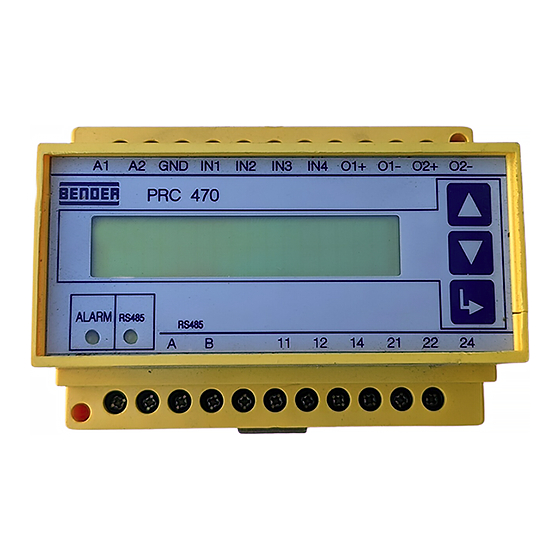
PRC470, PRC470E
Steuer- und Anzeigegerät
für RCMS- und EDS-Systeme
Bestimmungsgemäße Verwendung
Das Steuer- und Anzeigegerät PRC470 wird zur zentralen Steue-
rung von Isolationsfehlersucheinrichtungen EDS470, EDS473
oder von Differenzstrom-Suchsystemen RCMS470 eingesetzt.
Das PRC470 steuert bis zu
30 Differenzstrom-Auswertegeräte RCMS470-12 bzw.
30 Isolationsfehler-Auswertegeräte EDS47x-12
Das PRC470E steuert bis zu
60 Differenzstrom-Auswertegeräte RCMS470E-12 bzw.
60 Isolationsfehler-Auswertegeräte EDS47xE-12
Aufgaben des PRC470:
Zentrale Steuerung von EDS47x und RCMS470-Systemen
Datenaustausch per BMS-Bus
Anzeige der fehlerbehafteteten Abgänge und des aktuel-
len Fehlerstromes (oder Prüfstromes) pro Abgang
Einstellung unterschiedlicher Messstromwandlertypen
Individuelle Einstellmöglichkeiten für jedes Auswertegerät
Anpassung des Systems an Netzstörungen (EDS47x)
Steuerung von Auswertegeräten.
Die Synchronisation und Steuerung erfolgt über BMS-Bus.
Dieser Beipack informiert über den Einsatz des PRC470 in
RCMS470-Systemen. Der Einsatz in Isolationsfehlersucheinrich-
tungen EDS470, EDS473 ist in den jeweiligen Bedienungshand-
büchern beschrieben.
Dieser Beipack beschreibt PRC470 ab der eingebauten Software-
version 2.13.
Sicherheitshinweise allgemein
Montage, Anschluss und Inbetriebnahme nur durch Elektrofach-
kraft!
Beachten Sie unbedingt:
die bestehenden Sicherheitsvorschriften und
das beiliegende Blatt „Wichtige sicherheitstechnische Hin-
weise für BENDER-Produkte".
Funktionsbeschreibung
Das PRC470 erfüllt folgende Funktionen:
Einstellung des Speicherverhaltens
Einstellung der Arbeitsweise des Alarmrelais
Anzeige der Messstromwandlerabgänge, in denen die Ver-
bindung zum Messstromwandler unterbrochen oder kurz-
geschlossen ist.
Manuelle Anwahl bestimmter Messstromwandlerabgänge
Prüffunktion zum Test aller über den BMS-Bus angeschlos-
senen Geräte einschließlich der Prüfung der Messstrom-
wandlerkreise.
Einstellung, ob am jeweiligen Eingang eines RCMS470-12
bzw. EDS47x-12 ein Messstromwandler angeschlossen ist
108001 / 11.2004
Control and indicating device
Deutsch
for RCMS and EDS systems
Intended use
The control and indicating device PRC470 is used for the central
control of the insulation fault location systems EDS470, EDS473
or the residual current monitoring system RCMS470. The PRC470
controls up to
30 residual current evaluators RCMS470-12 or
30 insulation fault evaluators EDS47x-12
The PRC470E controls up to
60 residual current evaluators RCMS470E-12 or
60 insulation fault evaluators EDS47xE-12
Intended use of the PRC470:
Central control of EDS47x and RCMS470 systems
Data exchange via BMS bus
Indication of faulty subcircuits and the present faulty cur-
rent or (test current) per subcircuit
Setting of different types of meas. current transformers
Individual settings for each evaluator
Adaptation of the system to system interferences (EDS47x)
Control of evaluators.
Synchronisation and control takes place via BMS bus.
This documentation provides information on the utilization of
the PRC470 in RCMS470 systems. Details relating to utilization in
the insulation fault location systems EDS470 and EDS473 can be
found in the respective operating manuals.
This documentation describes the PRC470 with the installed soft-
ware version 2.13.
General safety instructions
Installation, connection and commissioning of electrical equip-
ment shall only be carried out by qualified electricians!
Particular attention shall be paid to:
the current safety regulations and
the enclosed sheet "Important safety instructions for
Bender products".
Description of functions
The PRC470 is equipped with the following functions:
Setting of the storage properties
Setting the operation of the alarm relay
Indication of measuring current transformer subcircuits in
which the connection to the measuring current trans-
former is interrupted or short-circuited.
Manual selection of specific measuring current trans-
former subcircuits.
Test function to test all devices connected via the BMS bus
including the testing of the meas. current transf. circuits.
Setting, as to whether or not a measuring current trans-
former is connected to the respective input of an
English
1
Advertisement

Related Manuals for Bender PRC470 Series


Summary of Contents for Bender PRC470 Series
- Page 1 Particular attention shall be paid to: die bestehenden Sicherheitsvorschriften und the current safety regulations and das beiliegende Blatt „Wichtige sicherheitstechnische Hin- the enclosed sheet "Important safety instructions for weise für BENDER-Produkte“. Bender products“. Funktionsbeschreibung Description of functions Das PRC470 erfüllt folgende Funktionen:...
-
Page 2: Operating Elements
PRC470, PRC470E oder nicht. RCMS470-12 or EDS47x-12 . Löschen aller Alarmmeldungen Deleting all alarm signals Zusätzliche Funktionen im RCMS-System: Additional functions in the RCMS system: Einstellung der individuellen Ansprechwerte für jeden Setting the individual response values for each channel Kanal Setting the prewarning level at between 10 and 100 % of Einstellung einer Vorwarnstufe zwischen 10 und 100 % des the response value... - Page 3 PRC470, PRC470E Maßbild Dimension diagram Abb. 2: alle Maße in mm Figure 2: All dimensions in mm Anschluss Connection Schließen Sie das Gerät entsprechend dem Anschlussplan in der Connect the device in accordance with the wiring diagram in the Anleitung des RCMS-Systems an. Beachten Sie dabei das Anzugs- manual that comes with the RCMS system.
- Page 4 PRC470, PRC470E Anschluss bei Einsatz in einem EDS47x-System Connection when applied in an EDS47x system Sichern Sie die Speisespannung U im IT-System zwei- Voltage supply U in IT systems requires two fuses! polig ab! Nur so ist im Falle des zweiten Fehlers sicher- This is the only way of guaranteeing that dangerous gestellt, dass gefähliche Fehlerströme abgeschaltet faulty current is switched off in the event of a second...
- Page 5 Control keys of the PRC470 PRC 470 PRC 470 V2.13 Bender, Grünberg Enter: Bestätigen des ausgewählten Menüpunktes Enter: confirm the selected menu item im Menü nach unten zu weiteren Funktionen; bzw. bei „m1“ Verlassen der scroll down the menu to further functions; and exit the Settings menu in ↓...
- Page 6 Rücksprache mit BENDER vor! Notieren Sie with BENDER! Please make a note of your settings. A Ihre Einstellungen. Für das RCMS470-System finden table has been provided in the appendix for docu- sie im Anhang eine Tabelle zur Dokumentation der menting the settings of the RCMS470 system.
- Page 7 PRC470, PRC470E Untermenüs Submenus m1: monitor m1: monitor Nach Aufruf von „m1: monitor“ mittels der Taste werden die When "m1: monitor" is called up using the key, the channels on Kanäle, auf denen der eingestellte Ansprechwert überschritten which the set response value was exceeded or not reached will be oder unterschritten wurde, angezeigt.
- Page 8 PRC470, PRC470E durch ein Gerät belegt, so erscheint die folgende Anzeige. the following indication will be shown. ↓ , ↑ ↓ , ↑ adr : 1 (adr : adr : 1 (adr : no adr 1 (menu: ) no adr 1 (menu: ) Ist zu einer Adresse ein Auswertegerät vorhanden, so sieht die If an evaluator has been assigned to the address, the indication Anzeige wie folgt aus.
- Page 9 PRC470, PRC470E Drücken Sie die Taste um den Vorwarnwert zu ändern. Press the key to change the prewarning value. ↓ , ↑ ↓ , ↑ 1-12 (k : 1-12 (k : Y2=100%*Y (ok: ) Y2=100%*Y (ok: ) Wählen Sie mit den Pfeiltasten den Wert der Vorwarnung. Ein- Select the prewarning value with the arrow keys.
- Page 10 PRC470, PRC470E Nach Aufruf von „m3: test“ mittels der Taste erscheint für meh- After "m3: test" is called up using the key, the indication "sys- rere Sekunden die Anzeige „system test“. tem test" is displayed for several seconds. m3: system test m3: system test .
- Page 11 PRC470, PRC470E relais Arbeitsweise des Alarmrelais des RCMS470-12 relay Operation of RCMS470-12 alarm relay no 12 14 = Arbeitsstrom no 12 14 = N/O operation nc 12 14 = Ruhestrom nc 12 14 = N/C operation memory Fehlerspeicher des RCMS470-12 bzw. EDS47x-12 memory Fault memory of the RCMS470-12 or EDS47x-12.
- Page 12 PRC470, PRC470E Ist ein Fehler vorhanden, so wird dies angezeigt. Any faults will be indicated. position (menü: position (menü: adr: 2k3 adr: 2k3 Um den aktuellen Messwert anzuzeigen, muss die The Memory function (m7) must be deactivated if you Memory-Funktion (m7) ausgeschaltet werden. wish to display the present measurement value.
- Page 13 Wählen Sie: current transformer that is being used. Select: *001 für BENDER-Messstromwandler mit einem Übersetzungsverhältnis 600/1 *001 for BENDER measuring current transformers with a transformation ratio of (Standard) 600/1 (standard) *001 ... für Messstromwandler mit einem anderen Übersetzungsverhältnis; für *001 ...
- Page 14 Faktor F: *001 Factor F: *001 Messstromwandlerüberwachung: Measuring current transformer monitoring: On Beispiel 2: Bender-Messstromwandler mit externem Shunt R = 150 Ω Example 2: Bender measuring current transformer with external shunt R = 150 Ω Einstellung: Faktor F: *002 Setting: Messstromwandlerüberwachung:...
- Page 15 Measuring current transformer monitoring: On Beispiel 5: Die zu messende Leitung ist mehrfach durch den Example 5: The line to be measured is "wound" several times BENDER-Messstromwandler „gefädelt“ um das Signal zu ver- through the BENDER measuring current transformer to stärken.
- Page 16 PRC470, PRC470E m9: conn. CT m9: conn. CT Im Menü „m9: conn. CT“ schalten Sie die Messstromwandlerüber- In the "m9: conn. CT“ menu, you can switch the measuring cur- wachung der an einem RCMS470-12 bzw. EDS47x-12 angeschlos- rent transformer monitoring of measuring current transformer senen Messstromwandlereingänge ein oder aus.
- Page 17 PRC470, PRC470E Wählen Sie mit den Pfeiltasten die Adresse des gewünschten Using the arrow keys, select the address of the required evaluator Auswertegerätes RCMS470-12. Drücken Sie dann die Taste RCMS470-12. Then press the key. ↓ ↑ ↓ ↑ adr: 3 (adr: adr: 3 (adr:...
-
Page 18: Technische Daten
PRC470, PRC470E Die maximale Gesamt-Messzeit (t) errechnen Sie wie folgt: The maximum overall measuring time (t) is calculated as follows: × × × × n 6s Anzahl der an einem EDS47x-12 angeschlossenen Number of measuring current transformers con- Messstromwandler nected to an EDS47x-12 24 s Grundzeit pro Messstromwandler 24 s... -
Page 19: Ordering Details
Genehmigung des Herausgebers. only with permission of the publisher. Änderungen vorbehalten! Subject to change! © 2004 BENDER Germany Dipl.-Ing. W. Bender GmbH & Co.KG Tel.: +49 (0)6401-807-0 E-Mail: info@bender-de.com • Londorfer Str. 65 35305 Grünberg Fax: +49 (0)6401-807-259 Internet: http://www.bender-de.com...
Need help?
Do you have a question about the PRC470 Series and is the answer not in the manual?
Questions and answers