
Related Manuals for Racal Instruments 1256


Summary of Contents for Racal Instruments 1256
- Page 1 (217) 352-9330 | Click HERE Find the Astronics / EADS / Racal 1256 at our website:...
- Page 2 ™ RACAL INSTRUMENTS 1256 SWITCHING SYSTEM Publication No. 980855 Rev. A EADS North America Test and Services, a division of EADS North America, Inc. 4 Goodyear, Irvine, CA 92618 Tel: (800) 722-2528, (949) 859-8999; Fax: (949) 859-7139 info@eads-nadefense.com sales@eads-nadefense.com helpdesk@eads-nadefense.com http://www.eads-nadefense.com...
- Page 3 THANK YOU FOR PURCHASING THIS EADS NORTH AMERICA TEST AND SERVICES PRODUCT For this product, or any other EADS North America Test and Services a division of EADS North America, Inc. (“EADS North America Test and Services”) product that incorporates software drivers, you may access our web site to verify and/or download the latest driver versions.
- Page 4 RETURN of PRODUCT Authorization is required from EADS North America Test and Services before you send us your product for service or calibration. Call or contact the Customer Support Department at 1-800-722-3262 or 1-949-859- 8999 or via fax at 1-949-859-7139. We can be reached at: helpdesk@eads-nadefense.com. PROPRIETARY NOTICE This document and the technical data herein disclosed, are proprietary to EADS North America Test and Services, and shall not, without express written permission of EADS North America Test and Services, be...
- Page 5 FOR YOUR SAFETY Before undertaking any troubleshooting, maintenance or exploratory procedure, read carefully the WARNINGS and CAUTION notices. This equipment contains voltage hazardous to human life and safety, and is capable of inflicting personal injury. If this instrument is to be powered from the AC line (mains) through an autotransformer, ensure the common connector is connected to the neutral (earth pole) of the power supply.
- Page 6 Artisan Technology Group - Quality Instrumentation ... Guaranteed | (888) 88-SOURCE | www.artisantg.com...
- Page 7 This page was left intentionally blank. Artisan Technology Group - Quality Instrumentation ... Guaranteed | (888) 88-SOURCE | www.artisantg.com...
-
Page 8: Table Of Contents
..........................1-1 INTRODUCTION ..........................1-1 Overview ............................1-1 Features............................1-2 Ease Of Use..........................1-2 Front and Rear Panels ......................1-2 Powerful Software .........................1-4 Items Shipped with the 1256 ......................1-4 Chapter 2 ..........................2-1 GETTING STARTED ........................2-1 Mounting Options .........................2-1 Main AC Power ..........................2-1 Installing Plug-Ins .........................2-3 Numbering of Plug-In Slots.......................2-3 Connecting to Plug-Ins ......................2-4... - Page 9 1256 User Manual Publication No. 980855 Rev. A Chapter 3 ..........................3-1 USING THE FRONT-PANEL CONTROLS ..................3-1 Introduction ..........................3-1 Front Panel...........................3-2 Understanding the Hierarchical Menu ..................3-2 The Five Menus ........................3-7 Operations Menu........................3-8 Viewing Relay States.......................3-10 Enabling a Digital Port .....................3-13 Path Control Menu ......................3-14 Defining a Path ........................3-14...
- Page 10 Publication No. 980855 Rev. A 1256 User Manual Selecting the GPIB Interface....................4-3 Setting the GPIB Address .....................4-4 Service Request (SRQ)......................4-5 Using the RS-232 Interface ......................4-5 Basic RS-232 Information .....................4-5 Equipment Required ......................4-6 DTE Versus DCE.......................4-6 Connecting to a Computer or Data Terminal ................4-6 Connecting to a Modem ......................4-7...
- Page 11 1256 User Manual Publication No. 980855 Rev. A IEEE 488.2 Common Commands ..................5-6 IEEE-488. 2 Status Description.....................5-7 Standard EVENT STATUS Register ..................5-9 STATUS BYTE Register .....................5-11 SERVICE Register ENABLE Register ................5-13 *CLS Command.......................5-13 *ESE Command ......................5-14 *ESE? Query ........................5-15 *ESR? Query ........................5-15 *SRE Command ......................5-15...
- Page 12 Publication No. 980855 Rev. A 1256 User Manual Command Input Buffer ......................5-25 Reply Output Buffer......................5-26 Specifying Channels in Commands..................5-27 Naming Relay Cards.......................5-28 Defining Module Names......................5-28 Removing Module Names ....................5-29 Reading the Presently Defined Module Names ..............5-30 Reading the Module Address for a Module Name ..............5-31 Storing the Module Names in Non-Volatile Memory ............5-31...
- Page 13 1256 User Manual Publication No. 980855 Rev. A Chapter 6 ..........................6-1 SCPI COMMAND REFERENCE ....................6-1 General ............................6-1 Chapter 7 ..........................7-1 DIGITAL MODULE OPERATION ....................7-1 General ............................7-1 Digital Module Ports .........................7-1 Asynchronous Digital Operation....................7-1 Synchronous Digital Operation .....................7-2 Mixing Synchronous and Asynchronous Modes of Operation ..........7-2 Specifying Ports on a Digital Module ..................7-3...
- Page 14 Selecting the Trigger Count ....................8-8 Selecting a Trigger Delay......................8-9 Arming and Disarming the 1256....................8-9 Generating a Single Trigger ....................8-12 Output Trigger Signals from the 1256 ................8-12 Selecting an Output Trigger Destination................8-12 Using Scan Lists and External Trigger Input ................8-13 Scan Lists ..........................8-14 Defining a Scan List ......................8-15...
- Page 15 RACK MOUNTING ........................B-1 Items Included........................B-1 Installing Rack-Mount Ears ....................B-1 Installing the 1256 Chassis Into a Rack ................B-2 viii EADS North America Test and Services Artisan Technology Group - Quality Instrumentation ... Guaranteed | (888) 88-SOURCE | www.artisantg.com...
- Page 16 Publication No. 980855 Rev. A 1256 User Manual Appendix C ........................C-1 TROUBLESHOOTING........................C-1 How to Use this Section ......................C-1 Power-Up ............................ C-1 Front-Panel Controls ........................C-2 RS-232 Remote Interface......................C-3 IEEE-488 (GPIB) Remote Interface .................... C-5 Plug-In Modules .......................... C-5 Non-Volatile Memory........................
- Page 17 Figure 3-1, Front-Panel Controls .....................3-2 Figure 4-1, Using the GPIB Interface....................4-3 Figure 4-2, Using the RS-232 Interface ...................4-7 Figure 4-3a, Using the 1256 with a Computer .................4-8 Figure 4-3b, Using the 1256 with a Modem ..................4-8 Figure 4-4, HyperTerminal Connection Dialog Box ...............4-17 Figure 4-5, Phone Number Dialog Box ..................4-17...
- Page 18 Figure 7-1 (C), Port 4 Data after DIG:SYNC:INDEX (@7(4)),3............7-11 Figure 7-1 (D), Port 4 Data after DIG:SYNC:DATA (@7(4)),77,78 ..........7-11 Figure 8-1, State Transition Diagram For Arming and Triggering the 1256........8-11 Figure 8-2, Using External Trigger In and External Trigger Out ............8-13 Figure B-1, Installing the Rack-Mount Ears ..................
- Page 19 1256 User Manual Publication No. 980855 Rev. A This page was left intentionally blank. EADS North America Test and Services Artisan Technology Group - Quality Instrumentation ... Guaranteed | (888) 88-SOURCE | www.artisantg.com...
- Page 20 Publication No. 980855 Rev. A 1256 User Manual DOCUMENT CHANGE HISTORY Revision Date Description of Change Revised per EO 29290 Revised format to current standards. Company name 8/21/08 revised throughout manual. Manual now revision letter controlled. Added Document Change History Page xiii.
- Page 21 1256 User Manual Publication No. 980855 Rev. A This page was left intentionally blank. EADS North America Test and Services Artisan Technology Group - Quality Instrumentation ... Guaranteed | (888) 88-SOURCE | www.artisantg.com...
-
Page 22: Chapter 1
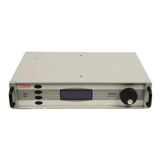
RF and microwave to 18GHz • Digital I/O with 96 channels per plug-in The user can easily insert these plug-ins into the 1256 Switching System to meet the needs of nearly any switching application. Figure 1-1 shows a picture of the 1256. -
Page 23: Features
The 1256 Switching System has many design features to make it Ease Of Use easy and convenient to use: • Fast Setup. There are no configuration jumpers or switches to be set. The 1256 is ready to use as soon as the plug-ins have been inserted. • Flexible Controller Interface. -
Page 24: Figure 1-3, 1256 Features, Rear Panel
Publication No. 980855 Rev. A 1256 User Manual Fuse Cover Plug-In Slots ON/OFF AC Input RS-232 Connection Trigger Trigger IEEE-488 Connection Figure 1-3, 1256 Features, Rear Panel 15.60 8.74 8.74 1.33 1.33 10.96 10.96 3.468 3.468 1.73 1.73 1.75 1.75 2.10... -
Page 25: Powerful Software
• Self-Test. Ensures that critical system components are functioning correctly. This test executes automatically at power-up. The following items are shipped with each 1256 Switching System: Items Shipped Introduction 1-4 EADS North America Test and Services Artisan Technology Group - Quality Instrumentation ... Guaranteed | (888) 88-SOURCE | www.artisantg.com... - Page 26 Publication No. 980855 Rev. A 1256 User Manual with the 1256 ITEM PART NUMBER QUANTITY 1256 Chassis Assembly 407724 User Manual 980855 AC Power Mains Cable 600620 Blanking Plates (to cover empty plug-in slots) 407667 Software Driver 921678 The following accessories may be ordered separately: •...
- Page 27 1256 User Manual Publication No. 980855 Rev. A This page was left intentionally blank. Introduction 1-6 EADS North America Test and Services Artisan Technology Group - Quality Instrumentation ... Guaranteed | (888) 88-SOURCE | www.artisantg.com...
-
Page 28: Chapter 2
1256 User Manual Chapter 2 Getting Started You may use the 1256 Switching System on a table or mount it in Mounting Options a standard NEMA 19” rack. See Appendix B, RACK MOUNTING the 1256 for instructions on installing the rack mount kit (Option 60) and placing the 1256 in a rack. - Page 29 Blue Ground (Earth) Green Green/Yellow CAUTION: Position the 1256 to allow easy access to the power switch on the rear-panel. CAUTION: Using this equipment in a manner not specified in this manual may impair the protection it normally provides. Getting Started 2-2 EADS North America Test and Services Artisan Technology Group - Quality Instrumentation ...
-
Page 30: Installing Plug-Ins
Figure 2-2, Inserting a Plug-In shows the proper way to install an Adapt-a-Switch plug-in into the 1256 chassis. When inserting the plug-in, engage the edges with the card guides of the 1256. Carefully slide the plug-in into the chassis until it stops, then push it firmly to engage its rear connectors with the 1256 backplane. -
Page 31: Connecting To Plug-Ins
Connecting to external hardware, refer to the user manuals of the individual plug- Plug-Ins ins. You are now ready to apply power to the 1256 Switching System. Activating Main See Figure 2-4, Activating Main AC Power for instructions on AC Power activating main power. -
Page 32: Self-Test
The contents of lines 2 through 4 depend upon which plug-ins are installed. The front-panel controls provide a way to verify which plug-ins are Verifying the installed in the 1256. For example, suppose the following plug-ins are Installed Plug-Ins installed: Slot 1:... -
Page 33: Closing A Relay
1256 User Manual Publication No. 980855 Rev. A contents of the next slot (slot 2): ----OPERATIONS---- >Slot 02: 1260-138A< Channel: 0 Status: Open The plug-in is 1260-138A. Continue to rotate the knob to view the contents of the remaining slots. -
Page 34: Opening A Relay
Then press the fourth key to confirm the opening of the relay. Pressing any other key cancels the change. If you have difficulties using the 1256 Switching System, refer to In Case of Appendix C, TROUBLESHOOTING to resolve the problem. If the... -
Page 35: Switching And Heat Dissipation
1256 User Manual Publication No. 980855 Rev. A The 1256 accommodates all Adapt-a-Switch plug-ins, which gives Switching and it exceptionally high-density switching capability. When switching a Heat Dissipation large quantity of signals near its maximum rated loading current, a plug-in generates heat due to the resistance of its conducting paths and relay contacts. -
Page 36: Chapter 3
Using the Front-Panel Controls The front-panel controls allow you to use the main features of the Introduction 1256 without the use of a remote interface such as IEEE-488 (GPIB) or RS-232. This may be useful during initial setup or when troubleshooting a system. -
Page 37: Front Panel
The top line shows the top level. The user begins by selecting a general type of function on line 1 (top line). Then, on line 2, the 1256 displays choices that are more specific to the general function that was selected on line 1. After the user selects from the choices on line 2, the 1256 shows related parameters on line 3. - Page 38 Publication No. 980855 Rev. A 1256 User Manual Press the top keypad switch. This selects line 1 (top line) of the display, as follows: >-----SETTINGS-----< Type: Remote Option: Source Status: GPIB NOTE: The selection markers “>” and “<” indicate the display line that is currently selected.
- Page 39 1256 User Manual Publication No. 980855 Rev. A Rotate the knob one more click to the right. The display shows: >----OPERATIONS----< Slot 01: 1260-118 Channel: 0 Status: Open Now the OPERATIONS menu is active. This menu contains the functions for operating the relays.
- Page 40 Publication No. 980855 Rev. A 1256 User Manual Rotate the knob one more click to the right. Line 2 now shows the contents of slot 3 (1260-120 plug-in): ----OPERATIONS---- >Slot 03: 1260-120 < Channel: 0 Status: Open Press the third keypad switch (corresponding to line 3 of the display).
- Page 41 Slot 03: 1260-120 Channel: 2 <Set to?: Closed On the fourth line, the 1256 asks whether to close the relay channel: 12. Press the fourth keypad switch to confirm that the relay channel should be closed (press any other key to cancel).
-
Page 42: The Five Menus
Publication No. 980855 Rev. A 1256 User Manual In the above example, the user starts at the top of the menu hierarchy and proceeds downward through the following levels: Level 1: Menu type: OPERATIONS, PATH CONTROL, SETTINGS, STORE / RECALL, SYSTEM (This example used OPERATIONS). -
Page 43: Operations Menu
Change the logic state of a digital output port on a digital I/O plug-in. Closing a Relay The 1256 front-panel enables the user to manually close and open relays on switch plug-ins. (For connector pin assignments of a plug-in, refer to its user manual.) For example, suppose a 1260-118 plug-in is installed in slot 3. - Page 44 Publication No. 980855 Rev. A 1256 User Manual Press the top key next to the display. This selects the top display line so that you can change it. The selection markers “>” and “<” appear on the line to indicate that it is selected.
-
Page 45: Viewing Relay States
1256 User Manual Publication No. 980855 Rev. A To open a relay, follow the steps given in the above section, Closing a Relay, except in step 6 rotate the knob until line 4 (bottom line) of the display reads as shown below:... - Page 46 Publication No. 980855 Rev. A 1256 User Manual The 1256 front-panel provides control of the output ports of a digital I/O plug-in. (For connector pin assignments of a plug-in, refer to its user manual.) For example, suppose a 1260-114TTL plug-in is installed in slot 3.
- Page 47 < Viewing a Digital Input Port The 1256 front-panel controls allow the user to view the data from input ports of digital I/O plug-ins. For example, suppose a 1260- 114TTL plug-in is installed in slot 3. Also suppose that port 5 of this plug-in is configured as an input (see Chapter 7, DIGITAL MODULE OPERATION for configuration instructions).
-
Page 48: Enabling A Digital Port
Publication No. 980855 Rev. A 1256 User Manual Slot 03: -114TTL >Port 05: Read < Value: 43 Now line 4 shows the states of the eight input signals of port 5, expressed as an eight-bit decimal number. By default, the display uses decimal notation. -
Page 49: Path Control Menu
SCPI path delete command. If the intent is to define the pathnames and make them accessible to the front panel after power is cycled to the 1256, the defined pathnames must also be stored in non-volatile memory. -
Page 50: Closing A Path
Characters extending beyond this limit are treated with wildcards when the filter mask is applied. Closing a Path The 1256 front-panel enables the user to manually close and open pathnames. For example, suppose four pathnames have been defined using the remote interface for a combination of different relays and plug- in cards –... -
Page 51: Opening A Path
Then press the fourth key to open the relay. Viewing Path States It is easy to view the states of pathnames on a 1256 system from the PATH CONTROL menu: Press the top key next to the display. Rotate the knob until the top line reads: >---PATH CONTROL---<... - Page 52 ---PATH CONTROL--- Select Filter Mask >PATH3_____________< Status: Open If no paths exist that meet the filter criteria, the 1256 will display: >---PATH CONTROL---< Select Filter Mask {no paths found} While selecting a mask, pressing the line 1 key or line 4 key will institute other changes.
-
Page 53: Settings Menu
• Screen saver timeout, in minutes. Selecting the Remote Interface Source The user may control the 1256 remotely by either of two remote interfaces: GPIB or RS-232. To select one of these as the active interface, follow these steps: Press the top key next to the display. Rotate the knob until the top line reads: >-----SETTINGS-----<... - Page 54 Local Lockout In some applications, it may be desirable to lock out (disable) the front-panel controls while controlling the 1256 via a remote interface. The 1256 provides two types of local lockout: • Automatic lockout: When the 1256 receives any...
- Page 55 The user may restore local control only by issuing a KLOCK OFF command. The display then returns to the state that it was in when the 1256 entered lockout mode. Manual control is also restored if the user cycles the power to the 1256.
- Page 56 Publication No. 980855 Rev. A 1256 User Manual > Option: Lockout < Status: Disabled If line 4 already shows the desired status, then no further action is necessary. Otherwise, select line 4. Then rotate the knob until the desired state (“Enabled” or “Disabled”) shows on line 4.
- Page 57 1256 User Manual Publication No. 980855 Rev. A “Type: Display:” -----SETTINGS----- > Type: Display < Option: Intensity Status: 75% Press the third key to select line 3 of the display (option): Rotate the knob until line 3 of the display reads as follows:...
- Page 58 Publication No. 980855 Rev. A 1256 User Manual Option: Format Status: Hex Press the third key to select line 3 of the display (option). Then rotate the knob until line 3 of the display reads as follows: -----SETTINGS----- Type: Display >...
- Page 59 1256 User Manual Publication No. 980855 Rev. A If line 4 already shows the desired status, then no further action is necessary. Otherwise, select line 4. Then rotate the knob until line 4 shows the desired status (enabled or disabled). This example uses “Disabled”:...
-
Page 60: Store/Recall Menu
After the user has set up the 1256 Switching System, the setup may be stored in non-volatile (flash) RAM. Later, the user may recall this setup to instantly restore the 1256 to the same state it was in earlier. The STORE/RECALL menu contains the functions used for doing this. - Page 61 Menu preferences include all preferences set by the user, such as remote interface settings, display intensity, and display format. The 1256 stores all menu preferences together as a single state. The 1256 can store one menu preference state, which is automatically restored when the power is turned on.
- Page 62 Publication No. 980855 Rev. A 1256 User Manual Updating Non-Volatile RAM Non-volatile (flash) RAM is inherently slow. If presets were stored directly in non-volatile RAM, the user would have to wait several seconds for each store operation. This may not always be an...
- Page 63 1256 User Manual Publication No. 980855 Rev. A To erase the entire non-volatile RAM, proceed as follows: Press the top key next to the display. Rotate the knob until the top line reads: >---STORE/RECALL---< Select line 2 (next to the top line) by pressing the second key.
-
Page 64: System Menu
ROM and the operating program that is currently stored in flash memory. For quick reference, this section lists the complete menu hierarchy Complete Menu for the 1256 Switching System. Menu items are indented according Listing to their levels of hierarchy. For example: LEVEL 1 (top line of display) - Page 65 1256 User Manual Publication No. 980855 Rev. A SETTINGS Remote Source GPIB RS-232 Lockout Disabled Enabled RS-232 Baud Rate 1,200 2,400 4,800 9,600 19,200 38,400 57,600 115,200 Data Bits Parity None Even Stop Bits Flow Control Disabled XON/XOFF RTS/CTS EOL Mode...
- Page 66 Publication No. 980855 Rev. A 1256 User Manual Intensity 100% Screen Saver Enabled Disabled Timeout 1 min 5 mins 10 mins 15 mins 30 mins 45 mins 1 hr STORE/RECALL State Defaults Recall Power Up Store Recall Preset #1 to 100...
- Page 67 1256 User Manual Publication No. 980855 Rev. A This page was left intentionally blank. Using the Front-Panel Controls 3-32 EADS North America Test and Services Artisan Technology Group - Quality Instrumentation ... Guaranteed | (888) 88-SOURCE | www.artisantg.com...
-
Page 68: Chapter 4
Programmable Instruments (SCPI), a universal programming language for test and measurement instruments. Chapter 5, SCPI COMMAND BASICS introduces SCPI and discusses the commands most frequently used with the 1256. For a discussion of all commands that may be used via the 1256 remote interfaces, Chapter... -
Page 69: Gpib Cabling Guidelines
Maximum of 15 devices (including controller) connected to the bus. Use a GPIB cable to connect the rear-panel GPIB connector on Connecting the the 1256 to the GPIB port of the host computer. Refer to Figure 4- GPIB Cables 1, Using the GPIB Interface. CAUTION: Avoid stacking more than three cables on any single connector. -
Page 70: Selecting The Gpib Interface
Connector GPIB Connector GPIB Cable Figure 4-1, Using the GPIB Interface Before using the GPIB interface with the 1256, you must select the Selecting the GPIB GPIB interface via the front-panel controls, as follows: Interface 1. Press the top key. Rotate the knob until the top line reads: >-----SETTINGS-----<... -
Page 71: Setting The Gpib Address
The 1256, as a GPIB bus member, must be assigned a unique Setting the GPIB address. This address can be set only by means of the front-panel Address controls. -
Page 72: Service Request (Srq)
Following this procedure will put the settings into non-volatile memory and allow them to be restored during instrument power-up. The 1256 may generate a service request (SRQ) in response to a Service Request variety of events. These events include detecting a programming... -
Page 73: Equipment Required
Using a shielded RS-232 cable, connect the nine-pin female RS- Terminal 232 connector on the 1256 rear panel to the RS-232 serial port on the computer or data terminal. Refer to Figure 4-2, Using the RS- 232 Interface. A suitable cable is available from EADS North America Test and Services: •... -
Page 74: Connecting To A Modem
RS-232 Connector RS-232 Cable Figure 4-2, Using the RS-232 Interface If you wish to connect the 1256 directly to a modem instead of a Connecting to a computer or data terminal, the connection will be DCE-to-DCE. A Modem DCE-to-DCE connection requires a special serial cable, known as a null-modem. -
Page 75: Figure 4-3A, Using The 1256 With A Computer
PIN 3 (TXD) PIN 7 (RTS) PIN 7 (RTS) PIN 8 (CTS) PIN 8 (CTS) PIN 5 (SIGNAL GND) PIN 5 (SIGNAL GND) Figure 4-3a, Using the 1256 with a Computer 9-PIN D-SUB 9-PIN D-SUB CONNECTOR CONNECTOR (MALE) (MALE) SPECIAL NINE-PIN RS-232 CABLE... - Page 76 Publication No. 980855 Rev. A 1256 User Manual To use the RS-232 interface with the 1256, the RS-232 interface Selecting the RS- must be selected via the front-panel controls, as follows: 232 Interface 1. Press the top key. Rotate the knob until the top line reads: >-----SETTINGS-----<...
-
Page 77: Setting The Flow Control Option
Flow control is a means by which the data terminal (or host computer acting as a terminal) may pace the flow of data coming from the 1256 so that the terminal has time to properly receive the data. It also allows the 1256 to pace commands coming from the terminal so that the 1256 has sufficient time to execute the commands as they arrive. - Page 78 Publication No. 980855 Rev. A 1256 User Manual 3. Rotate the knob until line 2 reads as shown below (lines 3 and 4 may differ): -----SETTINGS----- > Type: RS-232 < Option: Baud Rate Status: 9600 4. Press the third key to select line 3 of the display. Rotate the knob until line 3 indicates the “Flow Control”...
-
Page 79: Setting The Baud Rate
Set the RS-232 port of your data terminal or computer to operate at the same baud rate as the 1256. Refer to the user’s manual for your terminal for instructions on making these settings. If you are using a computer with terminal emulation, refer to the user’s... -
Page 80: Setting The Message Termination Characters
Each message to or from the 1256 must end with an end-of-line Setting the Message (EOL) character known as a terminator. You may select the EOL... -
Page 81: Setting The Data Bits, Stop Bits, And Parity
When using a data terminal, or a computer with terminal-emulation software, it is recommended that you set the 1256 to use the CR-only terminator. In this case, also set the data terminal or computer to half-duplex operation (local echo), with line feed appended to incoming messages (see your data terminal manual for information on how to do this). - Page 82 Publication No. 980855 Rev. A 1256 User Manual is an odd number). For most applications, this is set to “none”. To set these parameters, proceed as follows: 1. Press the top key. Rotate the knob until the top line reads: >-----SETTINGS-----<...
-
Page 83: Using Microsoft Hyperterminal
Following this procedure will put the settings into non-volatile memory and allow them to be restored during instrument power-up. One of the easiest ways to manually control the 1256 through the Using Microsoft RS-232 interface is to use HyperTerminal. HyperTerminal is a... -
Page 84: Figure 4-4, Hyperterminal Connection Dialog Box
Publication No. 980855 Rev. A 1256 User Manual Figure 4-4, HyperTerminal Connection Dialog Box Enter a name, such as “1256”, for the new connection. Then click on OK. HyperTerminal then displays the Phone Number dialog box as shown in Figure 4-5 (your screen may differ slightly). -
Page 85: Figure 4-6, Com Properties Dialog Box
Figure 4-6. Figure 4-6, COM Properties Dialog Box Set the baud rate to match the 1256 baud rate. Set the port for 8 data bits, no parity, one stop bit, and no flow control, as shown in Figure 4-6. -
Page 86: Figure 4-7, Main Communications Screen
Publication No. 980855 Rev. A 1256 User Manual Figure 4-7, Main Communications Screen Click on the File menu, then on Properties, to display the Properties dialog box shown in Figure 4-8 (your screen may differ slightly). EADS North America Test and Services GPIB and RS-232 Interfaces 4-19 Artisan Technology Group - Quality Instrumentation ... -
Page 87: Figure 4-8, Properties Dialog Box
1256 User Manual Publication No. 980855 Rev. A Figure 4-8, Properties Dialog Box Click on the Settings tab. The Settings dialog box then appears as shown in Figure 4-9 (your screen may differ slightly). Figure 4-9, Settings Dialog Box GPIB and RS-232 Interfaces 4-20 EADS North America Test and Services Artisan Technology Group - Quality Instrumentation ... -
Page 88: Figure 4-10, Ascii Setup Dialog Box
Figure 4-7. To finalize the connection, click on the Call menu, then click on Connect. To test the communications between the computer and the 1256, type the following command: *IDN? Then press Enter. The 1256 should respond with: Racal Instruments 1256 Switch System, 03.10... - Page 89 1256 User Manual Publication No. 980855 Rev. A NOTE: The version of HyperTerminal that is shipped with Microsoft Windows may not echo characters to the screen properly. An updated version is available from Hilgraeve, Inc. at: http://www.hilgraeve.com The new version is called HyperTerminal Private Edition.
-
Page 90: Chapter 5
Publication No. 980855 Rev. A 1256 User Manual Chapter 5 SCPI COMMAND BASICS The 1256 accepts commands over either the GPIB or serial SCPI Command interfaces. These commands follow the rules defined by the SCPI Overview standard. SCPI is an acronym for “Standard Commands For Programmable Instruments”, and defines standard command... - Page 91 1256 User Manual Publication No. 980855 Rev. A subsystem is shown below: [:ROUTe] :CLOSe <channel list> :OPEN <channel list> :ALL ROUTE is the root keyword of the command. This keyword is optional, since it is shown enclosed in square brackets. CLOSE and OPEN are the next level keywords.
-
Page 92: Command Keyword Long Form And Short Form
Publication No. 980855 Rev. A 1256 User Manual Each keyword defined by SCPI has both a long form and a short Command form. The long form is formed by using all letters shown in the Keyword Long keyword. The short form is formed by using only those letters shown in upper-case in the command tree. -
Page 93: Optional Keywords
GPIB or RS-232 serial interface is used. Terminator For commands sent through the GPIB interface, a command string sent to the 1256 must be terminated with one of the following: 1. An ASCII linefeed character (decimal 10, hex 0A, or a character ‘\n’). - Page 94 For further details on front-panel usage refer to Chapter 3: USING THE FRONT PANEL CONTROLS. The 1256 has the ability to interface with terminals and terminal emulation software. Unfortunately, a wide variation of capabilities exists in terminal/terminal emulators. Most terminal/terminal emulators generally treat the “ENTER”...
-
Page 95: Ieee 488.2 Common Commands
*RST; *STB?; *IDN? The IEEE-488. 2 common commands implemented by the 1256 are described later in this chapter. The 1256 complies with this standard for both GPIB and RS-232 operational modes. The 1256 supports all required IEEE-488.2 commands. In addition, IEEE 488.2 Common... -
Page 96: Ieee-488. 2 Status Description
While the GPIB operational mode of the 1256 is fully compliant with this standard, it is impossible for the 1256, or any instrument operating in the RS-232 operational mode for that matter, to satisfy the IEEE status requirements in all respects. -
Page 97: Figure 5-1, Ieee-488.2 Status Reporting Model
1256 User Manual Publication No. 980855 Rev. A Figure 5-1, IEEE-488.2 Status Reporting Model SCPI Command Basics 5-8 EADS North America Test and Services Artisan Technology Group - Quality Instrumentation ... Guaranteed | (888) 88-SOURCE | www.artisantg.com... -
Page 98: Standard Event Status Register
This flag is set when the instrument is powered on. User Request Bit 6, Bit weight = 64 decimal = 40 hexadecimal This bit is never set by the 1256 and will always read 0. Command Error Bit 5, Bit weight = 32 decimal = 20 hexadecimal This bit is set when a command error is detected by the 1256. - Page 99 Request Control Bit 1, Bit weight = 2 decimal = 2 hexadecimal This bit is never set by the 1256 and will always read 0. Operation Complete Bit 0, Bit weight = 1 decimal = 1 hexadecimal This bit is set when the *OPC command is executed.
-
Page 100: Status Byte Register
Publication No. 980855 Rev. A 1256 User Manual For example, if the PON and QYE bits of the Standard Event Status Register are set, but the Standard Event Status Enable Register value is 0, then the ESB of the Status Byte Register will not be set. - Page 101 Bit 4, bit weight = 16 decimal = 10 hexadecimal This bit is set when there is a message in the output buffer of the 1256 All other bits (3, 2, 1, and 0) of the Status Byte are not assigned and will always return 0.
-
Page 102: Service Register Enable Register
Publication No. 980855 Rev. A 1256 User Manual The Service Request Enable Register is used to individually SERVICE Register enable bits in the Status Byte to set the MSS bit of the Status Byte, ENABLE Register thereby generating an interrupt. When the bit of the Service Request Enable bit is set, and the corresponding bit of the Status Byte Register is set, then the MSS bit will be a 1. -
Page 103: Ese Command
1256 User Manual Publication No. 980855 Rev. A • The Questionable Status Enable Register is cleared to 0. To set this register, the STATUS:QUESTIONABLE:ENABLE command is issued. To read this register, the query STATUS:QUESTIONABLE:ENABLE? indicates whether this feature is enabled. -
Page 104: Ese? Query
Publication No. 980855 Rev. A 1256 User Manual *ESE? Query This query reads the value presently programmed for the Standard Event Status Enable Register. This reads the value as programmed by the “*ESE” command. *ESR? Query This query reads the value of the Standard Event Status Register. -
Page 105: Stb? Query
The *OPC command has no parameters. The only valid syntax for this command is: *OPC The *OPC? query causes the 1256 to reply with the value of “1" *OPC? Query when the query is executed. This query may be used to ensure... -
Page 106: Rst Command
1256 User Manual This reply indicates the manufacturer of the instrument is EADS North America Test and Services, that it is a 1256 Switch System, and the current firmware revision. The firmware revision is a numeric, floating point value. An example firmware revision is “3.10". -
Page 107: Tst? Query
If <location> is specified, it must be in the range from 0 through 100. If <location> is not specified, the instrument state will be saved into non-volatile memory location 100. State 0 is recalled at power-up. The 1256 is shipped without any SCPI Command Basics 5-18 EADS North America Test and Services... -
Page 108: Spe Command
Publication No. 980855 Rev. A 1256 User Manual data in state 0. This effectively tells the 1256 to open all relays at power-up. This default may be overwritten by placing all relays in the desired power-up state, and then executing the command. -
Page 109: Trg Command
NOTE: When bit 7 of the status byte (Service Requested) is set to show that SRQ is asserted, the 1256 will not respond to any GPIB commands until the interrupt has been serviced. Servicing may be done with a serial poll. After the interrupt has been serviced, the error code generated must be obtained via GPIB. - Page 110 SCAN operation. This bit is cleared after the settling time has elapsed. All of the other bits of this register are not used by the 1256. These bits will return a value of 0 when read. The Operation Status Enable Register enables individual bits to pass through to the Operation Status Event Register.
- Page 111 Event Register are read, they will return a value of 0. The Questionable Status Event Register may be programmed and queried, but will have no effect on the operation of the 1256. The following SCPI command tree shows the syntax of the SCPI...
-
Page 112: Scpi Parameter Type
7B hex = 123 decimal #H7B 173 octal = 123 decimal #Q173 When an integer value is returned In a reply from the 1256, the value will be a decimal number. Discrete Parameters Discrete parameters are used to program settings that have a limited number of values. -
Page 113: Boolean Parameters
Boolean Parameters Boolean parameters represent a single binary condition that is either true or false. The 1256 accepts "OFF" or "0" for a false condition. The 1256 accepts "ON" or "1" for a true condition. The following command uses a boolean parameter:... -
Page 114: Command Input Buffer
If the input buffer fills to capacity and the GPIB interface is the active interface, the NRFD signal is asserted on the GPIB bus. This indicates to the system controller that the 1256 is not able to accept more data until it parses existing commands and clears space in the input buffer. -
Page 115: Reply Output Buffer
1256, and to ensure that relays are in the programmed state, a query may be sent to the 1256. Once the reply to the query is read, you can be sure that the relays are in the programmed state. -
Page 116: Specifying Channels In Commands
Publication No. 980855 Rev. A 1256 User Manual To select a single channel in a command, both the address of the Specifying relay plug-in which contains the relay, and the channel number for Channels in the relay must be specified. The syntax to describe a single... -
Page 117: Naming Relay Cards
Slot 7 channel 15 Slot 8 channels 8 through 10 Each plug-in module controlled by a 1256 may be given a name. Naming Relay This name may be used in place of the slot number in any Cards command used to control a relay. -
Page 118: Removing Module Names
Publication No. 980855 Rev. A 1256 User Manual MOD:DEF A12345678901,8 Assigns name to plug-in module 2: MOD:DEF ZZZZZZ2,2 Examples of invalid commands are as follows. Incorrect; the module name must appear first: MOD:DEF 5,ABCD Incorrect; the module name must begin with a letter: MOD:DEF 4ASDF,8 Incorrect (for SCPI compatibility only);... -
Page 119: Reading The Presently Defined Module Names
The reply to this command consists of the presently defined module names, separated by a comma. Module names are stored internally in upper-case characters by the 1256. These upper-case names are returned in the reply. For example, suppose the following commands have been... -
Page 120: Reading The Module Address For A Module Name
Publication No. 980855 Rev. A 1256 User Manual The module address associated with a module name may be read Reading the Module using the MODULE:DEFINE? query. The syntax for this command Address for a Module Name [:ROUTe] :MODule :DEFine? <module name>... -
Page 121: Naming A Path
1256 User Manual Publication No. 980855 Rev. A A group of channels may also be assigned a name. When a group Naming a Path of channels is named, it is called a “path”. A path may consist not only of elements that must be closed (the closed channel list) but also of elements that must be opened (the open channel list) to complete the path. - Page 122 Publication No. 980855 Rev. A 1256 User Manual This associates the name dmm_to_P177 with the close channel list, channels 205 and 305, on the module whose name is defined as “matrix”: PATH:DEF dmm_to_P177,(@matrix(305,205)) This associates the name oscope1 with a close channel list for channels 0 and 3 on plug-in module 3 and an open channel list for plug-in module 5, channel 15.
-
Page 123: Defining Path Names
The reply to this command consists of the presently defined path names, each of which is separated by a comma. Path names are stored internally in upper-case characters by the 1256. These upper-case names are returned in the reply. For example, suppose the following commands have been... -
Page 124: Reading The Channel List For A Path Name
Publication No. 980855 Rev. A 1256 User Manual Then the query: PATH:CAT? returns the reply: DMM_2_PIN1,DMM_2_PIN2,CNTR_2_PIN1, CNTR_2_PIN2 The module address associated with a module name may be read Reading the Channel List using the PATH:DEFINE? query. The syntax for this command is:... - Page 125 1256 User Manual Publication No. 980855 Rev. A b. The input of the channel is disconnected from the “normally closed” output and connected to the “normally open” output (Single-Pole Double-Throw). c. The common input of a mux is connected to the output denoted by the channel number.
-
Page 126: Opening Relays
“0" if the corresponding relay is closed. Note that this is the opposite state from the CLOSE? query. The MOD:LIST? command may be used to query the 1256 for the Checking for types and slot numbers of the cards present in the system. -
Page 127: System Commands
The error queue holds up to 15 error messages. Each time an error is detected by the 1256, it adds a new error to the error queue. Each time the SYSTEM:ERROR? query is received, the oldest (least recent) error message is returned. -
Page 128: Scpi Compliance Information
In certain applications or environments where the 1256 is under automatic control, it may be desired or required that access to the 1256 be prohibited through the front panel user- interface. EADS North America Test and Services SCPI Command Basics 5-39 Artisan Technology Group - Quality Instrumentation ... -
Page 129: Non-Volatile Update
1256 User Manual Publication No. 980855 Rev. A For example, the command: SYST:KLOCK ON will cause the 1256 to display a remote operation screen on the display with a message indicating that local mode is in a lockout condition. The command:... - Page 130 To minimize the effects of the flash memory update cycle, the 1256 allows individual selections (i.e. include list, exclude lists, path names, menu selections, etc) to be instantaneously saved into intermediate volatile memory.
- Page 131 1256 User Manual Publication No. 980855 Rev. A This page was left intentionally blank. SCPI Command Basics 5-42 EADS North America Test and Services Artisan Technology Group - Quality Instrumentation ... Guaranteed | (888) 88-SOURCE | www.artisantg.com...
-
Page 132: Scpi Command Reference
This section contains a detailed description of each command that General is either specific to the 1256 or common to multiple switch modules. The commands are presented in Table 6-1. The commands accepted by the 1256 are shown using the SCPI syntax notation. - Page 133 ROUTE:CLOSE? and ROUTE:OPEN? are valid commands. Table 6-1 contains a synopsis of the commands implemented by the 1256. The maximum and minimum values and resolution are shown for numeric parameters. The commands marked with an asterisk (*) are NOT defined in the SCPI language. These commands follow the SCPI syntax rules for implementing the operation of the command.
-
Page 134: Table 6-1, Commands Implemented By The 1256
Publication No. 980855 Rev. A 1256 User Manual Table 6-1, Commands Implemented by the 1256 Command Default See page Notes ROUTE Subsystem: 6-1, 8-1 [:ROUTe] 5-2, 5-25 :CLOSe <channel list> 5-2, 5-28 :CLOSe? 5-38, 6-1 :OPEN <channel list> 5-2, 5-27... - Page 135 (Query Only) event are read, they will :CONDition? (Query Only) return a value of zero (0). :ENABle <enable mask> These commands are not used with the 1256 :ENABle? TRIGGER (and Related Commands) Subsystem: :TRIGger [:SEQuence] :COUNt <trigger count> (~ 2 billion) :DELay <trigger delay>...
- Page 136 (Command Only) 5-19 *RCL [<state>] (Command Only) 5-19 *OPT? (Query Only) *WAI no function in the 1256 5-21 EADS North America Test and Services SCPI Command Reference 6-5 Artisan Technology Group - Quality Instrumentation ... Guaranteed | (888) 88-SOURCE | www.artisantg.com...
- Page 137 1256 User Manual Publication No. 980855 Rev. A This page was left intentionally blank. SCPI Command Reference 6-6 EADS North America Test and Services Artisan Technology Group - Quality Instrumentation ... Guaranteed | (888) 88-SOURCE | www.artisantg.com...
-
Page 138: Digital Module Operation
Publication No. 980855 Rev. A 1256 User Manual Chapter 7 Digital Module Operation The 1256 may be used to control the 1260-114TTL, 1260- General 114CMOS, 1260-114OC, and 1260-114HVOC digital modules. These modules may be programmed to work in either the synchronous or asynchronous modes of operation. -
Page 139: Synchronous Digital Operation
A) Enable the drivers on the ports. B) Tell the 1256 which ports of the module are to be used as synchronous ports. C) Load data into the memory of the 1256. -
Page 140: Specifying Ports On A Digital Module
Publication No. 980855 Rev. A 1256 User Manual synchronous port is 7, then ports 0 through 7 will use the synchronous mode, and ports 8 through 11 will use the asynchronous mode. The following paragraphs describe the commands used to operate the 1260-114 modules. -
Page 141: Selecting The Mode Of Operation
1256 User Manual Publication No. 980855 Rev. A (@7(0)) Ports 0 and 11 on module 7: (@7(0,11)) Ports 0 through 11 on module 7: (@7(0:11)) Port 0 on module 7; port 4 on module 8: (@7(0),8(4)) Ports 0, 2 and 3 on module 7; ports 7 through 11 on module 8:... -
Page 142: Enabling And Disabling The Ports
Publication No. 980855 Rev. A 1256 User Manual The DIGITAL:OUTPUT:STATE command is used to enable or Enabling and disable the output drivers on one or more ports of the 1260-114 Disabling the Ports module. The 1260-114OC and 1260-114HVOC modules have open collector outputs, and so this command has no effect. - Page 143 1256 User Manual Publication No. 980855 Rev. A of which is in the range 0 to 255. The number of data bytes in the <data list> must agree with the number of ports specified in the <port list>. Examples of this command are shown below.
- Page 144 Publication No. 980855 Rev. A 1256 User Manual Synchronous Mode :DIGital :SYNChronous of Operation :STATe <module list> , { ON | OFF |1| 0 } :DATA <port> , <data list> :DATA? <port> :INDex <port list> , <index> :INDex? <port list>...
-
Page 145: Setting Up The Synchronous Test
1256 User Manual Publication No. 980855 Rev. A 1260-114 module using DIGITAL:SYNCHRONOUS:STATE command. Generate pulses on the CLKIN line of the 1260-114 module. The 1260-114 module will disarm itself when the number of pulses is equal to, or greater than, the maximum of:... - Page 146 Publication No. 980855 Rev. A 1256 User Manual Maximum value: 255, but less than, or equal to, the number of data points loaded Figures (A-D) show interaction between DIG:SYNC:DATA command and the DIG:SYNC:INDEX command. After power-on, or a *RST command, no data is loaded into any output port buffer of a 1260-114.
-
Page 147: Figure 7-1 (A), Port 4 Data After Dig:sync:data (@7(4)),10,20,30,40
1256 User Manual Publication No. 980855 Rev. A Figure 7-1 (A), Port 4 Data after DIG:SYNC:DATA (@7(4)),10,20,30,40 Location Data Index -> 4 Figure 7-1 (B), Port 4 Data after DIG:SYNC:DATA (@7(4)),50,60,70,80,90 Location Data Index -> 9 Digital Module Operation 7-10 EADS North America Test and Services Artisan Technology Group - Quality Instrumentation ... -
Page 148: Figure 7-1 (C), Port 4 Data After Dig:sync:index (@7(4)),3
Publication No. 980855 Rev. A 1256 User Manual Figure 7-1 (C), Port 4 Data after DIG:SYNC:INDEX (@7(4)),3 Location Data Index -> 3 Figure 7-1 (D), Port 4 Data after DIG:SYNC:DATA (@7(4)),77,78 Location Data Index -> 5 EADS North America Test and Services Digital Module Operation 7-11 Artisan Technology Group - Quality Instrumentation ... -
Page 149: Arming The Digital Modules
The DIGITAL:SYNCHRONOUS:POINTS command is used to define the maximum number of data bytes that will be acquired for the specified synchronous input port. This tells the 1256 how many data bytes to collect for the specified port(s). The value must be between 0 and 256. -
Page 150: Checking For Data Transfer Completion
Publication No. 980855 Rev. A 1256 User Manual DIG:SYNC:STATE (@3,5,9),ON Arm the digital modules at module addresses 3, 4, 5, 6, 9, and 11: DIG:SYNC:STATE (@3:6,11,9),ON After the module has been armed, it will remain armed until: The DIGITAL:SYNCHRONOUS:STATE command is used to disarm the module;... -
Page 151: Reading Data From A Synchronous Input Port
1256 User Manual Publication No. 980855 Rev. A Once the data transfer is complete, each of the synchronous input Reading Data from a ports may be read. The DIGITAL:SYNCHRONOUS:DATA? query Synchronous Input is used to read data from the synchronous input ports. -
Page 152: Clearing Data From Synchronous Input And Output Ports
The BUSY status line on the 1260-114 module is asserted until the 1256 is ready to accept a new CLKIN line. Any new CLKIN pulses received while the BUSY line is asserted will be ignored. -
Page 153: Synchronous And Asynchronous Example
1256 User Manual Publication No. 980855 Rev. A To illustrate a command sequence, assume module 7 is a 1260- Synchronous and 114 module. The following command sequence may be used to: Asynchronous Example Select ports 0 and 1 as synchronous output ports. - Page 154 Publication No. 980855 Rev. A 1256 User Manual Commands the 1260-114 to read the data. The reply will be a set of 4 data byte values, in decimal format, separated by commas: DIG:INPUT? (@7(6,7,10,11)) Enables the synchronous mode for module #7:...
- Page 155 1256 User Manual Publication No. 980855 Rev. A This page was left intentionally blank. Digital Module Operation 7-18 EADS North America Test and Services Artisan Technology Group - Quality Instrumentation ... Guaranteed | (888) 88-SOURCE | www.artisantg.com...
-
Page 156: Advanced Scpi Operations
Publication No. 980855 Rev. A 1256 User Manual Chapter 8 Advanced SCPI Operations The 1256 Switching System offers a number of advanced functions Introduction to give you precise control over the instrument. These functions can be accessed only via the IEEE-488 (GPIB) and RS-232 interfaces. -
Page 157: Include Lists
1256 User Manual Publication No. 980855 Rev. A The 1256 provides the capability to define sets of relays which Include Lists operate together. This feature is called an “include list”. When a relay on an include list is closed, all relays on that include list are closed. - Page 158 Publication No. 980855 Rev. A 1256 User Manual Any command which opens any of these relays will open all of them; and any command which closes any of these relays will close all of them. MOD:DEF power,3 MOD:DEF matrix,5 PATH:DEF thispath,(@8(0,4,12),power(14)) INCL (@power(15),matrix(323),thispath) The first three commands define module names and a path.
- Page 159 1256 User Manual Publication No. 980855 Rev. A For the remainder of this discussion of the INCL? query, assume the following commands have been executed: INCL (@1(0),2(0),4(0)) INCL (@2(7:10)) INCL (@3(16,19)) INCL (@1(3,5)) INCL (@4(1:4,14,23)) These commands define five distinct include groups.
-
Page 160: Using Exclude Lists
After power-up, and after a “*RST” command has been executed, all INCLUDE lists are deleted. The 1256 provides the capability to define sets of relays which are “mutually Using exclusive”. This feature is called an “exclude list”. When one relay on an Exclude exclude list is closed, all others in the exclude list are opened. - Page 161 1256 User Manual Publication No. 980855 Rev. A The error occurs because channels 1(0) and 1(6) are on an include list together and they are on an exclude list together. This creates a conflict since an attempt to close channel 1(0) would attempt to close channel 1(6) due to the include list association, but would be prevented from doing so by the exclude list.
-
Page 162: Using External Triggering
These signals connect to the External Trigger In and External Trigger Out connectors on the 1256 rear panel. Refer to Figure 7- 1, Using External Trigger In and External Trigger Out for connector location and signal information. -
Page 163: Selecting The Trigger Count
Scan List operation is initiated by sending an INIT:IMMEDIATE command (or INIT:CONTINUOUS command). This selects the 1256 external trigger input line. Each time a low-going pulse is received on the line, the scan list advances to the next element. After power-up, and after a *RST command, the trigger source is set to IMMEDIATE. -
Page 164: Selecting A Trigger Delay
Publication No. 980855 Rev. A 1256 User Manual The 1256 may be programmed to delay before acting on a trigger. Selecting a Trigger This provides the ability to slow down the scan list operation if so Delay desired. The TRIGGER:DELAY command is used to program the trigger delay. - Page 165 1256 User Manual Publication No. 980855 Rev. A are executed, the 1256 will accept up to 3 triggers. After the third trigger, scanning will be disabled since the trigger count value has been reached. At this point, channel 2 from module 1 will be closed, because it is the third element in the scan list.
-
Page 166: Figure 8-1, State Transition Diagram For Arming And Triggering The 1256
Publication No. 980855 Rev. A 1256 User Manual Figure 8-1, State Transition Diagram For Arming and Triggering the 1256 EADS North America Test and Services Advanced SCPI Operations 8-11 Artisan Technology Group - Quality Instrumentation ... Guaranteed | (888) 88-SOURCE | www.artisantg.com... -
Page 167: Generating A Single Trigger
1256 User Manual Publication No. 980855 Rev. A Generating a Single The 1256 may be armed, and a single trigger may be sent, using the TRIGGER:IMMEDIATE command. The syntax for this Trigger command is: :TRIGger [:SEQuence] :IMMediate This command is equivalent to the following:... -
Page 168: Using Scan Lists And External Trigger Input
Figure 8-2, Using External Trigger In and External Trigger Out A scan list allows you to specify a list of switching commands to be Using Scan Lists performed. Once you have defined this list, the 1256 will and External automatically sequence through the scan list, executing one... -
Page 169: Scan Lists
The TRIGGER:SOURCE command is used to select the input trigger. C) Program the 1256 to generate a trigger each time a relay is closed. The output trigger must be enabled, through the OUTPUT:TRIGGER command. -
Page 170: Defining A Scan List
CLOSE, OPEN, and PATH commands, but with one addition: special keywords may be used to indicate that all channels controlled by the 1256 are placed in the state as recalled from nonvolatile memory. In short, the <scan list> is comprised of: Individual channel designators. - Page 171 1256 User Manual Publication No. 980855 Rev. A and end with a number between 0 and 100. The following are valid state names: STATE0 STATE7 State53 State100 For example, the commands: PATH:DEF example,(@7(0,5,10,13)) SCAN (@1(323),4(0:2),5(8:5),example, 1(0),state14,1(224)) Define a path name (“example”) and then define a SCAN list. Each time a trigger is received, the next channel, path, or state in the scan list is closed after the previous channel or path is opened.
-
Page 172: Advance Verification Features
Features failures. From the standpoint of the 1256, switching failures fall into one of two classes – detectable and undetectable. An example of an undetectable failure is where a relay contact has welded closed through misuse. -
Page 173: Confidence Mode
The 1256 supports an operational mode that performs a high-level Confidence Mode system-wide verification. When Confidence Mode is enabled, the 1256 checks the status of all switches after it closes or opens any of them. The syntax for the command is shown below: [:ROUTe]... - Page 174 This process is illustrated with several examples. If the following command was sent: VERIFY:MASK (@2(0:10)),1 the 1256 would set the verification masks for plug-in module 2, channels 0 through 10 to “inverted” feedback. The following command would do the same thing except set the same channels...
-
Page 175: Saving/Recalling The Verification Masks
As was the case earlier, channel 11 is excluded by the mask and will not show up in the error report. In addition, the 1256 will show only the first ten failures it finds when a large number of channels are specified in a query. -
Page 176: Automatically Recalling Verification Masks At Startup
:STATE {OFF | ON | 0 | 1} :STATE? When a state of ON or 1 is specified, a special flag is stored inside the 1256 non-volatile memory structure that instructs it to automatically load any stored verification masks each time power is applied to the 1256. - Page 177 1256 User Manual Publication No. 980855 Rev. A This page was left intentionally blank. Advanced SCPI Operations 8-22 EADS North America Test and Seervices Artisan Technology Group - Quality Instrumentation ... Guaranteed | (888) 88-SOURCE | www.artisantg.com...
-
Page 178: Product Support
For worldwide support and the office closest to your facility, refer to the website for the most complete information http://www.eads- nadefense.com. Use the original packing material when returning the 1256 to EADS Warranty North America Test and Services, Inc. for calibration or servicing. The original shipping container and associated packaging material will provide the necessary protection for safe reshipment. - Page 179 1256 User Manual Publication No. 980855 Rev. A This page was left intentionally blank. Product Support 9-2 EADS North America Test and Services Artisan Technology Group - Quality Instrumentation ... Guaranteed | (888) 88-SOURCE | www.artisantg.com...
-
Page 180: Specifications
101 non-volatile memory locations for storage of switch states Non-Volatile Memory and user preferences Additional power-on state Automatically selected by 1256 according to each plug-in Switch Settling Time EADS North America Test and Services Specifications A-1 Artisan Technology Group - Quality Instrumentation ... Guaranteed | (888) 88-SOURCE | www.artisantg.com... -
Page 181: Remote Interface
1256 User Manual Publication No. 980855 Rev. A Remote Interface IEEE-488 (GPIB) Compliance: IEEE-488.2 Address Selection: Manual, via front-panel controls RS-232 Hardware Protocol: Data Communications Equipment (DCE). Connects directly to computer COM port with straight-through cable; no null modem. Baud Rates:... -
Page 182: Environmental
Publication No. 980855 Rev. A 1256 User Manual 90VAC to 250VAC, auto-ranging, 47-63Hz, AC Input 180VA max. DC Supply Output +5VDC @ 20A Environmental MIL-T-28800E Type III, Class 5, Style F General Temperature Operating: to +60 Storage: C to +70... -
Page 183: Safety
1256 User Manual Publication No. 980855 Rev. A Safety CE, EN61010-1 Safety Reliability MTBF >42,390 hours (with fan) Mechanical 3.5” high Dimensions 16.6” wide 11.3” deep 7 lbs., 11 oz. (3.5 kg) Chassis Weight Rack mount: Use optional rack-mount ears (Option 65) for... -
Page 184: Rack Mounting
Publication No. 980855 Rev. A 1256 User Manual Appendix B RACK MOUNTING The rack-mount kit, Option 60, includes the following items. Items Included Item Description Qty. Part Number Rack-mount Ear 456884 6X32X¾ Pan-Head Screw 616257 Instruction Sheet, Option 60 Rack Mount... -
Page 185: Installing The 1256 Chassis Into A Rack
1256 User Manual Publication No. 980855 Rev. A CAUTION: DO NOT attempt to support the mainframe in the rack with the rack mount ears only. Right angle runners or a base plate MUST be used to support the mainframe. Slide the instrument fully into the rack on previously installed right... -
Page 186: Troubleshooting
Publication No. 980855 Rev. A 1256 User Manual Appendix C Troubleshooting If you have difficulty using the 1256 Switching System, refer to How to Use this following troubleshooting tables. If you are still unable to Section resolve the problem, contact the EADS North America Test and Services Customer Support Department (refer to Chapter 9, PRODUCT SUPPORT). -
Page 187: Front-Panel Controls
PROBLEM POSSIBLE CAUSES WHAT TO DO • • Display goes blank Power has been Verify that the 1256 AC input is (was working). interrupted. connected to a live mains outlet. • Verify that the 1256 power switch is still in the ON position. -
Page 188: Rs-232 Remote Interface
115,200. • • Remote terminal receives Baud rate of 1256 not Set baud rate of 1256 to match unintelligible text from 1256. matched to baud rate of that of the data terminal (see No intelligible text is received terminal. - Page 189 • Baud rate too high for cable Change to a lower baud rate. and terminal being used. Make sure that the new 1256 baud rate matches the new terminal baud rate (to set the 1256 baud rate, see Chapter 4, GPIB and RS-232 Interfaces, under the heading Setting the Baud Rate).
-
Page 190: Ieee-488 (Gpib) Remote Interface
232 Interfaces, under the heading Setting the GPIB Address). • • The 1256 is set to the same Make sure that the 1256 is set GPIB address as another to a unique GPIB address(to device in the system. set the 1256 GPIB address,... -
Page 191: Non-Volatile Memory
1256 User Manual Publication No. 980855 Rev. A Non-Volatile Memory PROBLEM POSSIBLE CAUSES WHAT TO DO • • Switch states or menu Switch states and menu After saving switch states or settings that have been settings must be saved in a... -
Page 192: Plug-In Modules
Publication No. 980855 Rev. A 1256 User Manual Appendix D PLUG-IN Modules Every Adapt-a-Switch switch plug-in comes with an information How to Use This providing packet technical information that is specific to that Section module. Insert these packets after this page so that they become part of this manual. - Page 193 1256 User Manual Publication No. 980855 Rev. A This page was left intentionally blank. PLUG-IN Modules D-2 EADS North America Test and Services Artisan Technology Group - Quality Instrumentation ... Guaranteed | (888) 88-SOURCE | www.artisantg.com...
-
Page 194: Index
Publication No. 980855 Rev. A 1256 User Manual INDEX AC power, 2-1, 2-2 Execution Error, 5-9 automatic lockout, 5-42 firmware revision, 4-4, 5-16 baud rate, 4-10, 4-11, 4-12 flow control, 4-10, 4-18, 5-25, 5-26 bus trigger, 5-21 front panel, 2-3, 5-41... - Page 195 Publication No. 980855 Rev. A 1256 User Manual OPC, 5-6, 5-10, 5-16, 5-27 RS-232 parameters, 4-13, 4-15 OPEN, 5-2, 5-18, 5-22, 5-27, 5-33, 5-34, 5-37, RTS, 4-10, 4-14, 4-18, 5-26 5-38, 5-39 safety, 5-26 Operation Complete, 5-10, 5-16 SCPI, 2-6, 4-1, 4-12, 5-2, 5-3, 5-4, 5-11, 5-13,...
Need help?
Do you have a question about the 1256 and is the answer not in the manual?
Questions and answers