Table of Contents
Advertisement
Quick Links
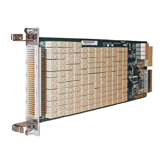
1450 144 Crosspoint
2A, Two-Wire Matrix
Plug-in Switch Card
Tel: (800) 722-2528, (949) 859-8999; Fax: (949) 859-7139
info@eads-nadefense.com
helpdesk@eads-nadefense.com
Copyright 2009 by EADS North America Test and Services, a division of EADS North America, Inc.
Printed in the United States of America. All rights reserved. This book or parts thereof may not be
reproduced in any form without written permission of the publisher.
Racal Instruments™
User Manual
Publication No. 980937-1450 Rev. A
EADS North America Test and Services,
a division of EADS North America, Inc.
4 Goodyear, Irvine, CA 92618
Publication Date: August 11, 2009
sales@eads-nadefense.com
http://www.eads-nadefense.com
Advertisement
Table of Contents

Related Manuals for Racal Instruments 1450D


Summary of Contents for Racal Instruments 1450D
- Page 1 Racal Instruments™ 1450 144 Crosspoint 2A, Two-Wire Matrix Plug-in Switch Card User Manual Publication No. 980937-1450 Rev. A EADS North America Test and Services, a division of EADS North America, Inc. 4 Goodyear, Irvine, CA 92618 Tel: (800) 722-2528, (949) 859-8999; Fax: (949) 859-7139 info@eads-nadefense.com...
- Page 2 THANK YOU FOR PURCHASING THIS EADS NORTH AMERICA TEST AND SERVICES PRODUCT For this product, or any other EADS North America Test and Services a division of EADS North America, Inc. (“EADS North America Test and Services”) product that incorporates software drivers, you may access our web site to verify and/or download the latest driver versions.
- Page 3 TRADEMARKS AND SERVICE MARKS All trademarks and service marks used in this document are the property of their respective owners. Racal Instruments and ActivATE are trademarks of EADS North America Test and Services in the United States. Windows, Visual Studio, Outlook, Excel, and IntelliSense are trademarks of the Microsoft Corporation Inc.
- Page 4 FOR YOUR SAFETY Before undertaking any troubleshooting, maintenance or exploratory procedure, read carefully the WARNINGS and CAUTION notices. This equipment contains voltage hazardous to human life and safety, and is capable of inflicting personal injury. If this instrument is to be powered from the AC line (mains) through an autotransformer, ensure the common connector is connected to the neutral (earth pole) of the power supply.
-
Page 5: Table Of Contents
1450 User Manual Table of Contents Chapter 1 Overview and Specifications.................1-1 Overview............................1-1 Specifications..........................1-2 Input............................1-2 DC Performance: 1450D/F (2-wire) ...................1-2 AC Performance (50Ω): 1450D (4x36)..................1-3 AC Performance (50Ω): 1450F (4x36) ..................1-3 Interface Data ..........................1-3 Software .............................1-4 Environmental Data ........................1-4 Conformance Testing .........................1-4 Reliability ............................1-4... - Page 6 1450 User Manual Publication No. 980937-1450 Rev. A Main Control Tab ........................3-22 Configuration Tab ........................3-22 Commonly Used SCPI Commands....................3-23 Channel Descriptors........................3-23 PATH Command .......................... 3-24 SCAN Command.......................... 3-25 INDEX ............................ 1 EADS North America Test and Services...
- Page 7 Figure 3-13: Example Visual C++ Program Using the IVI Driver ............3-16 Figure 3-14: Example Visual C++ Program Using the IVI Driver ............3-18 Figure 3-15: Example ActivATE Test Script for the 1450D .............3-19 Figure 3-16: ActivATE Main Tab for the 1450D Card ..............3-20 Figure 3-17: ActivATE Main Tab for the 1450F Card..............3-21...
- Page 8 1450 User Manual Publication No. 980937-1450 Rev. A This page was left intentionally blank. EADS North America Test and Services...
- Page 9 Publication No. 980937-1450 Rev. A 1450 User Manual List of Tables Table 2-1: 1450D Front Panel Pin Assignment (Columns E, D) ............2-4 Table 2-2: 1450D Front Panel Pin Assignment (Columns C, B, A)...........2-5 Table 2-3: 1450F Front Panel Pin Assignment (Columns E, D) ............2-6 Table 2-4: 1450F Front Panel Pin Assignment (Columns C, B, A) ...........2-7...
- Page 10 1450 User Manual Publication No. 980937-1450 Rev. A This page was left intentionally blank. EADS North America Test and Services...
- Page 11 Publication No. 980937-1450 Rev. A 1450 User Manual EADS North America Test and Services...
- Page 12 1450 User Manual Publication No. 980937-1450 Rev. A This page was left intentionally blank. EADS North America Test and Services...
- Page 13 Publication No. 980937-1450 Rev. A 1450 User Manual Document Change History Revision Date Description of Change 8/11/09 Document Control release EADS North America Test and Services...
- Page 14 1450 User Manual Publication No. 980937-1450 Rev. A This page was left intentionally blank. EADS North America Test and Services...
-
Page 15: Chapter 1 Overview And Specifications
Chapter 1 Overview and Specifications Overview The Racal Instruments™ 1450D and 1450F cards are expandable, high- density switch matrices for the 1800 Series Source/Measure Switch platform. The cards quickly and easily plug into a switching system like the Model 1830 Source/Measure Switch using LXI/GPIB/USB interfaces and easily expand with the internal Signal Raceway analog bus. -
Page 16: Specifications
Electromechanical relays support bi-directional operation. 1450 Series plug-in cards are available in the following two-wire configurations: 1450D (4x36): Using the analog bus of the Model 1830 Source/Measure Switch, matrix dimensions can be expanded up to 4x324 1450F (8x18): Using the analog bus of the Model 1830 Source/Measure... -
Page 17: Ac Performance (50Ω): 1450D (4X36)
Publication No. 980937-1450 Rev. A 1450 User Manual AC Performance (50Ω): 1450D (4x36) Bandwidth (-3 dB) > 65 MHz Insertion Loss 100 KHz: < 0.1 dB 1 MHz: < 0.2 dB 10 MHz: < 0.3 dB 65 MHz: < 3.0 dB Isolation 100 KHz: >... -
Page 18: Software
Running total of operations stored in on-board non- volatile memory Mean Time Between Failure (MTBF) The 1450D MTBF is 34,939 hours at 25° C and the 1450F MTBF is 33,910 hours at 25° C, calculated in accordance with MIL-HDBK-217FN2. Factors affecting relay life expectancy are: 1. -
Page 19: Mechanical
For additional information regarding the 160-pin cable assembly, see Chapter 2, Installation Instructions. Model/Description Part No. Racal Instruments™ 1450D, 4x36, 2-wire, 2A Matrix Switch Card 405331 Racal Instruments 1450F, 8x18, 2-wire, 2A Matrix Switch Card 405330 160-pin cable assembly, 6 ft... - Page 20 1450 User Manual Publication No. 980937-1450 Rev. A This page was left intentionally blank. Overview and Specifications 1-6 EADS North America Test and Services...
-
Page 21: Chapter 2 Installation Instructions
Publication No. 980937-1450 Rev. A 1450 User Manual Chapter 2 Installation Instructions Unpacking and Inspection CAUTION Use standard ESD procedures including ground straps and static-safe work surfaces whenever handling the 1450 card. 1. Upon receipt, remove the card from its packaging and inspect for damages. -
Page 22: Plug-In Card Shield
1450 User Manual Publication No. 980937-1450 Rev. A Figure 2-1: Inserting a Plug-In Card Plug-in Card Shield If you wish to reduce the electromagnetic interference (EMI) between cards, install an optional card shield (PN 408190) immediately above the cards. Refer to the Figure 2-2. 1. -
Page 23: Front Panel Connector Pin Assignment
See Figure 2-3 for a diagram of the front panel connector pin numbering. See Tables 2-1 and 2-2 for the pin assignment of the 1450D card and Tables 2-3 and 2-4 for the pin assignment of the 1450F card. -
Page 24: Table 2-1: 1450D Front Panel Pin Assignment (Columns E, D)
1450 User Manual Publication No. 980937-1450 Rev. A Table 2-1: 1450D Front Panel Pin Assignment (Columns E, D) SIGNAL SIGNAL COL_L_22 COL_H_22 COL_L_34 COL_H_34 COL_L_21 COL_H_21 COL_L_33 COL_H_33 COL_L_20 COL_H_20 COL_L_32 COL_H_32 COL_L_19 COL_H_19 COL_L_31 COL_H_31 COL_L_18 COL_H_18 COL_L_30 COL_H_30... -
Page 25: Table 2-2: 1450D Front Panel Pin Assignment (Columns C, B, A)
Publication No. 980937-1450 Rev. A 1450 User Manual Table 2-2: 1450D Front Panel Pin Assignment (Columns C, B, A) SIGNAL SIGNAL SIGNAL COL_L_23 COL_H_23 COL_L_35 COL_H_35 COL_L_11 COL_H_11 SGND COL_L_10 COL_H_10 SGND COL_L_9 COL_H_9 SGND COL_L_8 COL_H_8 SGND SGND COL_L_7... -
Page 26: Table 2-3: 1450F Front Panel Pin Assignment (Columns E, D)
1450 User Manual Publication No. 980937-1450 Rev. A Table 2-3: 1450F Front Panel Pin Assignment (Columns E, D) SIGNAL SIGNAL ROW_L_7 ROW_H_7 ROW_L_6 ROW_H_6 COL_L_17 COL_H_17 ROW_L_5 ROW_H_5 COL_L_16 COL_H_16 ROW_L_4 ROW_H_4 COL_L_15 COL_H_15 ROW_L_3 ROW_H_3 COL_L_14 COL_H_14 ROW_L_2 ROW_H_2 COL_L_13 COL_H_13 ROW_L_1... -
Page 27: Table 2-4: 1450F Front Panel Pin Assignment (Columns C, B, A)
Publication No. 980937-1450 Rev. A 1450 User Manual Table 2-4: 1450F Front Panel Pin Assignment (Columns C, B, A) SIGNAL SIGNAL SIGNAL COL_L_11 COL_H_11 SGND COL_L_10 COL_H_10 SGND COL_L_9 COL_H_9 SGND COL_L_8 COL_H_8 SGND SGND COL_L_7 COL_H_7 SGND COL_L_6 COL_H_6 SGND SGND SGND... -
Page 28: Mating Connectors
1450 User Manual Publication No. 980937-1450 Rev. A Mating Connectors The following 1450 mating connector accessories are available from your EADS North America Test and Services representative or through our main sales contact numbers. 160-Pin Connector Kit with backshell and pins, P/N 408192 The 160-Pin Connector Kit consists of a connector housing, plastic backshell, and 160 crimp pins. -
Page 29: Table 2-5: Cable Assembly Pin, Signal, And Wire Reference
Publication No. 980937-1450 Rev. A 1450 User Manual Table 2-5: Cable Assembly Pin, Signal, and Wire Reference Cable Wire No. Pin No. Wire Color Reference Card Signal PIN - A32 Cable 1 WHT_BLK_YEL_GRY PIN - A31 Cable 1 WHT_BLK_ORG_VIO PIN - A30 Cable 1 WHT_BLK_RED_VIO SGND... - Page 30 1450 User Manual Publication No. 980937-1450 Rev. A Cable Wire No. Pin No. Wire Color Reference Card Signal PIN - B22 Cable 1 WHT_BLK_GRY PIN - B21 Cable 1 WHT_BLK_ORG COL_H_7 PIN - B20 Cable 1 WHT_BLU PIN - B19 Cable 1 WHT_BRN PIN - B18...
- Page 31 Publication No. 980937-1450 Rev. A 1450 User Manual Cable Wire No. Pin No. Wire Color Reference Card Signal PIN - C11 Cable 2 WHT_BLU_VIO PIN - C10 Cable 2 WHT_YEL_VIO PIN - C9 Cable 2 WHT_ORG_BLU COL_L_3 PIN - C8 Cable 2 WHT_RED_BLU PIN - C7...
- Page 32 1450 User Manual Publication No. 980937-1450 Rev. A Cable Wire No. Pin No. Wire Color Reference Card Signal PIN - E32 Cable 1 WHT_BLK_BLU_VIO PIN - E31 Cable 1 WHT_BLK_YEL_VIO COL_L_22 PIN - E30 Cable 1 WHT_BLK_ORG_BLU COL_L_34 PIN - E29 Cable 1 WHT_BLK_RED_BLU PIN - E28...
-
Page 33: Installing Coding Keys On Cards And Connectors
Publication No. 980937-1450 Rev. A 1450 User Manual Installing Coding Keys on Cards and Connectors Included with each connector kit or cable assembly is a set of hardware (Figure 2-5) which you can use to key code your connector to specific plug-in cards to prevent cables from being misconnected to the wrong card. - Page 34 1450 User Manual Publication No. 980937-1450 Rev. A This page was left intentionally blank. Installation Instructions 2-14 EADS North America Test and Services...
-
Page 35: Chapter 3 Operation
1450 User Manual Chapter 3 Operation Block Diagram Figure 3-1 shows simplified block diagrams of the 1450D and 1450F cards where row and column intersections represent matrix crosspoints. Figure 3-1: 1450 Block Diagram Note: all wires shown are 2-wire pairs. -
Page 36: Operating The 1450 Switch Card
1450 User Manual Publication No. 980937-1450 Rev. A Operating the 1450 Switch Card The 1450 switch card is controlled by the firmware in the 1800-series Source/Measure Switch platform into which it is installed. There are several ways to operate the 1450 switch card. These include: ... -
Page 37: Analog Bus Safety Interlock Circuit
Publication No. 980937-1450 Rev. A 1450 User Manual <model code>,<manufacturer>,<serial number>,<revision info> A typical response for the 1450 card is: XI1450,EADS NORTH AMERICA,112508363942,1.0-0.0-2.1 If no card is recognized in the slot 9, the reply would be NONE,EADS NORTH AMERICA,0,0.0-0.0-0.0 Analog Bus Safety Interlock Circuit CAUTION The 1830 Analog Bus is rated for 300 VAC/VDC on ABus and 150 VAC/VDC on SABus. -
Page 38: Lxi Web Page Controls
The relay change is immediate. Figure 3-3 shows the Relay Control web page for the 1450D card. Figure 3-4 shows the web page for the 1450F card. Note the message on the top of the screen in those figures regarding the Analog Bus Safety Interlock. -
Page 39: Figure 3-3: 1450D Relay Control Tab
Publication No. 980937-1450 Rev. A 1450 User Manual Figure 3-3: 1450D Relay Control Tab Figure 3-4: 1450F Relay Control Tab EADS North America Test and Services Operation 3-5... -
Page 40: Scpi Commands Tab
1450 User Manual Publication No. 980937-1450 Rev. A SCPI Commands Tab The SCPI Commands tab (Figure 3-5) allows you to send SCPI commands to the card. A few common SCPI commands have clickable icons along the top of the tab including: ... -
Page 41: Module Overview Tab
Publication No. 980937-1450 Rev. A 1450 User Manual Module Overview Tab The Module Overview tab (Figure 3-6) allows you to review current card information including model and serial number, revision levels, channel/state configuration, relay cycle counts, and emergency reset status. Figure 3-6: Module Overview Tab Clicking Generate Report generates a status report and shows the results on the information screen to the right of the button. -
Page 42: Ivi Driver Operation
100 = row 1, column 0 417 = row 4, column 17 The 1450D card has 4 rows and 36 columns, so the valid matrix channel numbers range from 0 to 335. The 1450F card has 8 rows and 18 columns, so the valid matrix channel numbers for this card are 0 to 717. -
Page 43: Table 3-1: Ivi Driver Channel Names
9907 = connect row 6 to single-ended analog bus (SABUS) 5 & 6 9908 = connect row 7 to single-ended analog bus (SABUS) 7 & 8 Since the 1450D has only 4 rows, channels 9905 through 9908 are not supported by this module. -
Page 44: Ivi Configuration Store
1450 switch cards plugged into your 1800-series platform, then you will need to create three sessions to control them. The examples in this section demonstrate how to add a 1450D model switch card to the IVI configuration store. To add a 1450F model, follow the example but replace “1450F”... -
Page 45: Figure 3-8: Creating A New Ivi Driver Session
Publication No. 980937-1450 Rev. A 1450 User Manual Figure 3-8: Creating a New IVI Driver Session EADS North America Test and Services Operation 3-11... -
Page 46: Figure 3-9: Associating Software Module With Ivi Driver Session
(in this case via the Ethernet interface). This is shown in Figure 3-10. Note that the “Resource Descriptor” is the VISA resource descriptor for the 1800 series platform into which the 1450D module is plugged. VISA supports the Ethernet interface (as shown), the USB interface, or the GPIB interface. -
Page 47: Figure 3-10: Creating A Hardware Asset For The Ivi Driver Session
1450D. Select the Initial Settings tab and modify the “Module Address” entry to match the plug-in slot of the 1450D card. In the example shown in Figure 3-11, the module address is set to 5. -
Page 48: Figure 3-12: Creating A Logical Name For The Ivi Driver Session
1450 User Manual Publication No. 980937-1450 Rev. A The final step in the configuration process is to create a logical name. To do this, right mouse click on the Logical Names tree element and select the Create new (case sensitive) item. Enter the name of the new logical session (shown in Figure 3-12 as “RIXI1450D_L1”) and then select the driver session created previously (“RIXI1450D_S1”). -
Page 49: Visual C++ Example
(channels 0 and 9901). It then waits for the channel debounce to occur, and finally opens all channels. // Example console test program showing how to use the // basic methods of the 1450D IVI driver #include "stdafx.h"... -
Page 50: Figure 3-13: Example Visual C++ Program Using The Ivi Driver
1450 User Manual Publication No. 980937-1450 Rev. A strDriverSetupOptions; spDriver->Initialize(LPCTSTR(strResourceDesc), VARIANT_FALSE, VARIANT_FALSE, LPCTSTR(strOptions)); // cast the specific driver to an // IVISwtch class compliant one spSwitch = spDriver; // close channel 0 _bstr_t channel1 = _bstr_t("ROW00_H"); _bstr_t channel2 = _bstr_t("COL00_H"); spSwitch->Path->Connect(channel1, channel2);... - Page 51 EADS.RiXI1450D.Interop.dll The interoperability DLLs are installed when the IVI shared components are installed (first two items above) and when the 1450D IVI driver is installed. These are typically installed into the following directory, but your system may have a different IVI installation directory:...
-
Page 52: Activate Operation
Figure 3-14: Example Visual C++ Program Using the IVI Driver ActivATE Operation The 1450D and 1450F cards may also be used within the ActivATE™ test platform environment. Consult the 1800-series manual for a description of how to configure your system for use with the 1800-series plug-in cards. -
Page 53: Main Tab
An open check box means that relay is open. Figures 3-16 and 3-17 show the Main tab of the ActivATE GUI for the 1450D EADS North America Test and Services... -
Page 54: Figure 3-16: Activate Main Tab For The 1450D Card
Figure 3-18 shows the various messages and variations on the Main tab depending on the current situation. For more information, refer to the Analog Bus Safety Interlock Circuit section earlier in this chapter. Figure 3-16: ActivATE Main Tab for the 1450D Card Operation 3-20 EADS North America Test and Services... -
Page 55: Figure 3-17: Activate Main Tab For The 1450F Card
Publication No. 980937-1450 Rev. A 1450 User Manual Figure 3-17: ActivATE Main Tab for the 1450F Card Figure 3-18: Analog Bus Safety Interlock Information on ActivATE Screen. EADS North America Test and Services Operation 3-21... -
Page 56: Main Control Tab
1450 User Manual Publication No. 980937-1450 Rev. A Main Control Tab The Manual Control tab (Figure 3-19) acts very similar to the web page version. It allows you to send commands to and read replies from the system. Figure 3-19: ActivATE Manual Control Tab Configuration Tab The Configuration tab (Figure 3-20) provides the means to locate the XML command file that contains all of the relevant SCPI commands for this card. -
Page 57: Commonly Used Scpi Commands
(1 to 9) <module address> identifies the relay channel being controlled. <channel> The valid <channel> numbers for a 1450D are as follows: 0 to 35 (row 0, columns 0 to 35) 100 to 135... -
Page 58: Path Command
9905 to 9908 (SABUS relays to row 4 to 7) The correspondence between channel numbers and front panel connection is shown in Tables 2-1 and 2-2 and Figure 2-3 of this manual. The following would be valid channel descriptors for a 1450D switch card plugged into slot 5: (@5(0)) -
Page 59: Scan Command
Publication No. 980937-1450 Rev. A 1450 User Manual CLOSE (@TURN_OFF_POWER) is received, it will close all of the channels defined for the path named TURN_OFF_POWER. SCAN Command The SCAN command is used to instruct the 1800-series system to scan across a set of relay channels. The relay channels can occur in any order, across any number of plug-in modules. - Page 60 1450 User Manual Publication No. 980937-1450 Rev. A That is, if the scan list consists of 50 channels, each of those channels could have a unique sequence defined and then associated with it. For more information on the SCAN and SEQUENCE commands, consult the SCPI section of your 1800-series system user manual.
-
Page 61: Index
Publication No. 980937-1450 Rev. A 1450 User Manual INDEX ABUS ground plane, 2-5, 2-7 block diagram, 3-1 identifying, 3-2 installing IVI driver channel, 3-9 voltage limits, 3-3 card shield, 2-2 web page, 3-20 connector code key, 2-13 ActivATE plug-in card, 2-1 operation, 3-18 software, 1-2 configuration store, 3-10... - Page 62 1450 User Manual Publication No. 980937-1450 Rev. A DC performance, 1-2 tools menu, 3-7 environmental, 1-4 Visual C#, 3-17 input, 1-2 Visual C++, 3-15 interface data, 1-3 voltage limits, 3-3 mechanical, 1-4, 1-5 web page controls, 3-4 reliability, 1-4 modules overview tab, 3-7 software, 1-4 relay control tab, 3-4 switching, 1-2...
Need help?
Do you have a question about the 1450D and is the answer not in the manual?
Questions and answers