Table of Contents
Advertisement
Quick Links
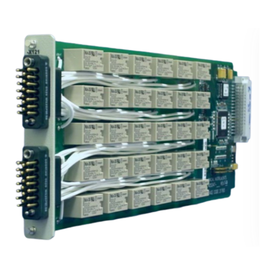
1260 VXI SWITCHING CARD
20 CHANNEL PLUG-IN
MODEL 1260-X121
Tel: (800) 722-2528, (949) 859-8999; Fax: (949) 859-7139
5730 Northwest Parkway Suite 700, San Antonio, TX 78249
Tel: +33 (0)1 39 23 22 22; Fax: +33 (0)1 39 23 22 25
29-31 Cobham Road, Wimborne, Dorset BH21 7PF, United Kingdom
Tel: +44 (0) 1202 872800; Fax: +44 (0) 1202 870810
Tel: +39 (0)2 6123 901; Fax: +39 (0)2 6129 3606
Racal Instruments Group Limited, Technologie Park, D-51429 Bergisch Gladbach, Germany
PUBLICATION DATE: October 21, 2005
Copyright 2005 by Racal Instruments, Inc. Printed in the United States of America. All rights reserved.
This book or parts thereof may not be reproduced in any form without written permission of the publisher.
PUBLICATION NO. 980914-X121
RACAL INSTRUMENTS
United States
(Corporate Headquarters and Service Center)
4 Goodyear Street, Irvine, CA 92618
Tel: (210) 699-6799; Fax: (210) 699-8857
Europe
(European Headquarters and Service Center)
18 Avenue Dutartre, 78150 LeChesnay, France
Via Milazzo 25, 20092 Cinisello B, Milan, Italy
Tel: +49 2204 844205; Fax: +49 2204 844219
info@racalinstruments.com
sales@racalinstruments.com
helpdesk@racalinstruments.com
http://www.racalinstruments.com
info@racalinstruments.de
www.racalinstruments.de
Advertisement
Table of Contents

Related Manuals for Racal Instruments 1260-X121


Summary of Contents for Racal Instruments 1260-X121
- Page 1 PUBLICATION DATE: October 21, 2005 Copyright 2005 by Racal Instruments, Inc. Printed in the United States of America. All rights reserved. This book or parts thereof may not be reproduced in any form without written permission of the publisher.
- Page 2 THANK YOU FOR PURCHASING THIS RACAL INSTRUMENTS PRODUCT. For this product, or any other Racal Instruments product that incorporates software drivers, you may access our web site to verify and/or download the latest driver versions. The web address for driver downloads is: http://www.racalinstruments.com/downloads...
- Page 3 Authorization is required from Racal Instruments before you send us your product for service or calibration. Call your nearest Racal Instruments support facility. A list is located on the last page of this manual. If you are unsure where to call, contact Racal Instruments, Inc. Customer Support Department in Irvine, California, USA at 1-800-722-3262 or 1-949-859-8999 or via fax at 1-949-859-7139.
- Page 4 FOR YOUR SAFETY Before undertaking any troubleshooting, maintenance or exploratory procedure, read carefully the WARNINGS and CAUTION notices. This equipment contains voltage hazardous to human life and safety, and is capable of inflicting personal injury. If this instrument is to be powered from the AC line (mains) through an autotransformer, ensure the common connector is connected to the neutral (earth pole) of the power supply.
-
Page 5: Table Of Contents
1260-X121 User Manual Table of Contents Chapter 1 ..........................1-1 SPECIFICATIONS .......................... 1-1 Introduction...........................1-1 Specifications ..........................1-2 Power Dissipation.........................1-3 About MTBF ..........................1-4 Ordering Information ........................1-5 Chapter 2 ..........................2-1 INSTALLATION INSTRUCTIONS....................2-1 Unpacking and Inspection ......................2-1 Reshipment Instructions.......................2-1 Installation ............................2-1 Module Configuration ........................2-2 Front Panel Connectors......................2-3... - Page 6 1260-X121 User Manual Chapter 3 ..........................3-1 MODULE OPERATION ........................3-1 Operating Modes..........................3-1 Operating In Message-Based Mode.....................3-1 Channel Descriptors For The 1260-121 ...................3-1 Reply To The MOD:LIST? Command ..................3-2 Operating in Register-Based Mode ....................3-3 Chapter 4 ..........................4-1 PRODUCT SUPPORT........................4-1 Product Support ...........................4-1 Reshipment Instructions.......................4-1...
- Page 7 Table 2-1, 1260-X121 Front-Panel Connections ................2-4 Table 2-2, Mating Connectors and Pins...................2-6 Table 3-1, Register Offset Addresses of the 1260-X121 Module ............3-4 Table 3-2, ID Register Functionality of the 1260-X121 Module ............3-4 Table 3-3, Register0 Functionality of the 1260-X121 Module............3-5 Table 3-4, Register1 Functionality of the 1260-X121 Module............3-5...
- Page 8 1260-X121 User Manual This page was left intentionally blank.
-
Page 9: Chapter 1
1260-X121 User Manual Chapter 1 SPECIFICATIONS The 1260-X121 is a plug-in switch module developed for the Racal Introduction Instruments 1260-100X Adapt-a-Switch Carrier. The 1260-X121 includes the following features: • Standard Adapt-a-Switch plug-in design, providing for ease of replacement • Data-Driven embedded descriptor, allowing immediate use with any Option-01T switch controller, regardless of firmware revision level. -
Page 10: Specifications
1260-X121 User Manual The 1260-X121 is a 20-channel single-wire switch consisting of 20 individual SPST relay switches and 10 1X2 switches by software configuration. The 1260-X121 plug-in fits into a 1260-100X Adapt- a-Switch Carrier. Bandwidth (-3dB) >300KHz Specifications Insertion Loss 300 KHz <... -
Page 11: Power Dissipation
For example, if a 1260-X121 module (containing 20 relays) has 5 relays closed, passing a current of 10 A, then: Total power dissipation =... -
Page 12: About Mtbf
By using a chassis with high cooling capacity, such as the Racal Instruments 1261B, almost any configuration may be realized. The 1260-X121 MTBF is 783,549 hours at 25°C and 718,344 About MTBF hours at 30°C, calculated in accordance with MIL-HDBK-217E, with the electromechanical relays set at 50% rated load at 85°C. -
Page 13: Ordering Information
The relay used on the 1260-X121 plug-in is Racal part no. 310344. The relay manufacturer’s specifications for this relay are: Life Expectancy... - Page 14 1260-X121 User Manual This page was intentionally left blank. Racal Instruments © 2005 Specifications 1-6...
-
Page 15: Chapter 2
ESD Shielding bag and use plastic spray foam to surround and protect the instrument. 3. Reship in either the original or a new shipping carton. Installation of the 1260-X121 Switching Module into a 1260-100X Installation Carrier assembly is described in the Installation section of the 1260-100X Adapt-a-Switch Carrier Manual. -
Page 16: Module Configuration
SPST relay switches ten SPST configuration Configuration relays. This architecture permits the 1260-X121 module to be organized via software as twenty SPST or ten 1X2 switches. For a block diagram of the 1260-X121, see Figure 2-1. CH00 CH01 CONTROL... -
Page 17: Front Panel Connectors
1260-X121 User Manual The 1260-X121 has two 20-pin front-panel connectors, labeled Front Panel J200 and J201. It has one pin for each input and one for each Connectors output. See Figure 2-2 for pin numbering. Table 2-1 shows the mapping of channel numbers to connector pins. Information about available mating connectors is provided immediately after Table 2-1. -
Page 18: Table 2-1, 1260-X121 Front-Panel Connections
1260-X121 User Manual Table 2-1, 1260-X121 Front-Panel Connections CH00 J200-C J200-F CH01 J200-B J200-E CH02 J200-A J200-D CH03 J200-K J200-N CH04 J200-J J200-M CH05 J200-H J200-L CH06 J200-S J200-V CH07 J200-R J200-U CH08 J200-P J200-T CH09 J200-X J200-W CH10 J201-C... - Page 19 1260-X121 User Manual CH00 J200-C J200-F (J200-B) J200-E CH02 J200-A J200-D (J200-K) J200-N CH04 J200-J J200-M (J200-H) J200-L CH06 J200-S J200-V (J200-R) J200-U CH08 J200-P J200-T (J200-X) J200-W CH10 J201-C J201-F (J201-B) J201-E CH12 J201-A J201-D (J201-K) J201-N CH14 J201-J...
-
Page 20: Mating Connectors
1260-X121 User Manual Mating connector accessories are available for the 1260-X121: Mating Connectors 20 Pin Connector Kit with backshell and pins P/N 407660 The 20-pin connector kit consists of a connector housing, aluminum backshell, and twenty solder-cup pins. The pins are also available from Positronic in crimp versions and for smaller wire diameters. -
Page 21: More About Maximum Current Ratings
The listed values are obtained from several tests in laboratories under room- temperature conditions (21°C). The contact is considered to be in free air. The maximum current carrying for the 1260-X121 is 10 A. •... -
Page 22: Installation
Installation Carrier, engage the printed circuit board into the grooves of the desired carrier slot. Slide the 1260-X121 into the carrier until its connector mates with the connector on the carrier backplane. Push firmly to fully seat the connector. Tighten the two retaining screws at the top and bottom of the 1260-X121 plug-in. -
Page 23: Chapter 3
This is a number is in the range from 1 through 12, inclusive. • <channel> is the 1260-X121 channel to operate. This is a number in the range from 0 through 19, inclusive. Multiple individual channels may be specified using the following channel descriptor syntax: @ <module address>... -
Page 24: Reply To The Mod:list? Command
<module address> : <module-specific identification string> For the 1260-X121 module the string value is: 1260-X121 20-CHANNEL SPST 10A SWITCH Thus, for a 1260-X121 whose module address is 2, the reply to this query would be: 2 : 1260-X121 20-CHANNEL SPST 10A SWITCH Racal Instruments ©... -
Page 25: Operating In Register-Based Mode
The A24 address offset is usually expressed in hexadecimal. A typical value of 204000 is used in the examples that follow. A 1260-X121 with a module address of 7 would have the base A24 address computed as follows: Base A24 Address of 1260-X121 = 204000... -
Page 26: Table 3-1, Register Offset Addresses Of The 1260-X121 Module
1260-X121 relays. Table 3-2 through 3-5 provides a detailed explanation of each register and how it interacts with the 1260-X121 module. Table 3-1, Register Offset Addresses of the 1260-X121 Module Register Register Offsets to Add to Base Module Address Name... -
Page 27: Table 3-3, Register0 Functionality Of The 1260-X121 Module
1260-X121 User Manual Table 3-3, Register0 Functionality of the 1260-X121 Module Register 0 Register Table Module Version Functionality Description Relay 00 (0: relay open 1: relay closed) Relay 01 (0: relay open 1: relay closed) Relay 02 (0: relay open 1: relay closed) -
Page 28: Table 3-6, Register3 Functionality Of The 1260-X121 Module
Note: Open: Indicates C not connected to NO contact Closed: Indicates C connected to NO contact Table 3-7, EPROM Descriptor Functionality of the 1260-X121 Module EPROM Descriptor Register Register Table Module Version Functionality Description Each time this register is read, it advances a memory pointer to the next memory location in the on-board EPROM. - Page 29 Because of the 1260-X121 relay driver architecture, registers A and B will read back inverted from what was written to them. The VISA I/O library may be used to control the module. The VISA...
- Page 30 1260-X121 User Manual This page was left intentionally blank. Racal Instruments © 2005 Module Operation 3-8...
-
Page 31: Chapter 4
For worldwide support and the office closes to your facility, refer to the Support Offices section on the following page. Use the original packing material when returning the 1260-X121 to Reshipment Racal Instruments for calibration or servicing. The original shipping... -
Page 32: Support Offices
Tel: +44 (0) 1202 872800; Fax: +44 (0) 1202 870810 Via Milazzo 25, 20092 Cinisello B, Milan, Italy Tel: +39 (0)2 6123 901; Fax: +39 (0)2 6129 3606 Racal Instruments Group Limited, Technologie Park, D-51429 Bergisch Gladbach, Germany Tel: +49 2204 844205; Fax: +49 2204 844219 Racal Instruments ©... -
Page 33: Repair And Calibration Request Form
1260-X121 User Manual Repair and Calibration Request Form To allow us to better understand your repair requests, we suggest you use the following outline when calling and include a copy with your instrument to be sent to the Racal Repair Facility.
Need help?
Do you have a question about the 1260-X121 and is the answer not in the manual?
Questions and answers