Sign In
Upload
Download
Table of Contents
Contents
Add to my manuals
Delete from my manuals
Share
URL of this page:
HTML Link:
Bookmark this page
Add
Manual will be automatically added to "My Manuals"
Print this page
×
Bookmark added
×
Added to my manuals
Manuals
Brands
Paragon Manuals
Controller
EL71
General instructions manual
Paragon EL71 General Instructions Manual
Single channel & two channel electronic time controls
Hide thumbs
1
Table Of Contents
2
3
4
5
6
7
8
9
10
11
12
13
14
15
16
17
18
19
20
21
22
23
24
25
26
27
28
29
30
31
32
33
34
35
36
37
38
39
40
41
42
43
44
45
46
47
48
49
50
51
52
53
54
55
56
57
58
59
60
page
of
60
Go
/
60
Contents
Table of Contents
Bookmarks
Table of Contents
Table of Contents
Introduction
Specifications
Programming Capabilities
Electrical
Environmental
Physical
Functional Description
Control Layout
Input Connections
Keypad Description
Hierarchy of Control
Programming
Programming Overview
Memory Clear
Set Time
Configuration
Astro
Events
Input Configuration
Sensor Events
Holiday
Override
Run
Accessories
Temperature Sensor
Light Sensor
Computer Software
Application Examples
Programming Worksheets
Advertisement
Quick Links
1
Programming Capabilities
2
Programming Overview
3
Programming
4
Set Time
5
Configuration
6
Events
7
Override
Download this manual
http://waterheatertimer.org/Paragon-timers-and-manuals.html#EL
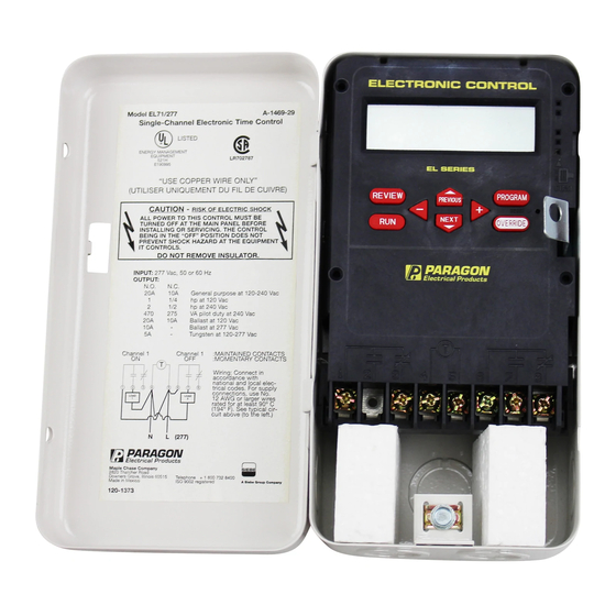
EL71 - Single Channel & EL72 - Two Channel
Electronic Time Controls
General Instructions
Table of
Contents
Previous
Page
Next
Page
1
2
3
4
5
Advertisement
Table of Contents
Need help?
Do you have a question about the EL71 and is the answer not in the manual?
Ask a question
Questions and answers
Related Manuals for Paragon EL71
Controller Paragon EL7100 General Instructions Manual
Electronic time controls (30 pages)
Controller Paragon EC7000 Series General Instructions Manual
Single channel electronic time controls (10 pages)
Controller Paragon EC7004 Series General Instructions Manual
Single channel electronic time controls (10 pages)
Controller Paragon EC7004 SPST General Instructions Manual
Single channel electronic time controls (10 pages)
Controller Paragon EC4000 Quick Start Manual
Single-channel electronic time control (2 pages)
Controller Paragon EL72 General Instructions Manual
Single channel & two channel electronic time controls (60 pages)
Controller Paragon EL712 General Instructions Manual
Twelve channel electronic time control (15 pages)
Controller Paragon EL78 General Instructions Manual
Eight channel electronic time control (28 pages)
Controller Paragon DTC 1000 Operation & Maintenance Instructions Manual
Digital temperature controller (24 pages)
Controller Paragon DTC 1000 series Troubleshooting Manual
(16 pages)
Controller Paragon Sentry Xpress 2.0 Instructions Manual
Digital temperature controller (8 pages)
Controller Paragon TnF 2 Installation Manual
Portable controller (2 pages)
Controller Paragon Sentry Xpress SC Series Quick Start Manual
(2 pages)
This manual is also suitable for:
El72
Table of Contents
Save PDF
Print
Rename the bookmark
Delete bookmark?
Delete from my manuals?
Login
Sign In
OR
Sign in with Facebook
Sign in with Google
Upload manual
Upload from disk
Upload from URL


Need help?
Do you have a question about the EL71 and is the answer not in the manual?
Questions and answers