
Related Manuals for National Flooring Equipment 3535


Summary of Contents for National Flooring Equipment 3535
-
Page 1: Instruction Manual
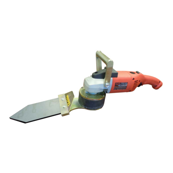
Rev A CORNER PREPARATION & POLISHING INSTRUCTION MANUAL TOOL Read Manual Before Operating Machine 122713... -
Page 3: Table Of Contents
Table of Contents Table of Contents ................................3 Features and Specifi cations ............................4 Safety ................................... 5-9 General Rules For Safe Operation ........................5-6 Grinding Equipment Guidelines ..........................6 Specifi c Safety Guidelines ............................. 6 Grounding ................................8 Extension Cords ..............................8 Guidelines For Using Extension Cords ....................... -
Page 4: Features And Specifi Cations
Features and Specifi cations Top Handle Handheld Size Brazed Diamonds & Polishing Pads Variable Speed FEATURES Handheld Size - allows the ability to work in areas which larger grind- Variable Speed - 0-6,000 variable speed motor powers various tool- ers won’t. ing options with a oscillating movement. -
Page 5: Safety
All operators must view the instruction video. Extra copies of the manual and video are avail- able by contacting National Flooring Equipment. KNOW YOUR EQUIPMENT: Read this manual carefully to learn equipment applications and limitations, potential hazards associated with this type of equipment. -
Page 6: Grinding Equipment Guidelines
Safety 24. ALWAYS KEEP THE MOTOR AIR VENT FULLY OPENED. Do not allow motor air vent to become blocked. Keep motor air vent open to allow the motor to cool. GRINDING EQUIPMENT GUIDELINES DO NOT FORCE GRINDER INTO THE WORK SURFACE: The machine will work faster, smoother and safer when used at the rate for which it was designed. - Page 7 Safety WARNING: ALWAYS WEAR RESPIRATOR PROTECTION, APPROPRIATE FOR THE APPLICATION, AS SPECIFIED BY OSHA REGU- LATIONS AND YOUR EMPLOYER. NEVER OPERATE OR MAINTAIN EQUIPMENT BEFORE READING AND UNDERSTANDING THE INSTRUCTIONS FOR OPERATION AND MAINTENANCE. OBEY ALL SAFETY SIGNS AND INSTRUCTIONS WHILE OPERATING OR MAINTAINING EQUIPMENT.
-
Page 8: Grounding
Safety WARNING: ELECTRICAL CORDS CAN BE HAZARDOUS. MISUSE CAN RESULT IN FIRE OR DEATH BY ELECTRICAL SHOCK. READ CAREFULLY AND FOLLOW ALL DIRECTIONS. GROUNDING Jobsite receptacles can vary. Check the voltage at different receptacles on the jobsite for a more accurate voltage reading. 15 amp GFI outlets are not recommended. GROUNDED TOOLS: TOOLS WITH THREE PRONG PLUGS FIG. - Page 9 Safety GUIDELINES FOR USING EXTENSION CORDS (CONTINUED) • Keep away from water. Do not use if wet. • Inspect thoroughly before each use. DO NOT USE IF DAMAGED. • Make sure equipment is not running before disconnecting cord. • FULLY INSERT plug into outlet. •...
-
Page 10: Machine Operation
Machine Operation BREAKING IN After the fi rst half hour (30 minutes) of use, check all screws and fi ttings for a tight secure fi t. ON/OFF SWITCH These grinders are equipped with a dead-man switch. Press to start and release to stop. The tool has a safety lock which prevents it from being started accidently. -
Page 11: Maintenance
Maintenance WARNING: TO REDUCE THE RISK OF INJURY, ALWAYS UNPLUG YOUR TOOL BEFORE PERFORMING ANY MAINTENANCE. NEVER DISASSEMBLE THE TOOL OR TRY TO DO ANY REWIRING ON THE TOOL’S ELECTRICAL SYSTEM. MAINTAINING TOOLS Keep your tool in good repair by adopting a regular maintenance program. Before use, examine the general condition of your tool. -
Page 12: Complete Parts List
Complete Parts List PART# DESCRIPTION PART# DESCRIPTION 1 6300-1 BASE PLATE 7 71231 BEARING 25MM ID 2 6300-2 RUBBER RING 8 73006 1/4-20 X 3/4 BUTTON HEAD CAP SCREW 4 3 6300-3 BEARING CUP 9 73014 1/4-20 X 1/2 HEXHEAD BOLT 4 6300-4 CUTTING HEAD 10 73019... -
Page 13: Parts Lists And Diagrams
Parts List and Diagrams TOOLING ATTACHMENTS PART# DESCRIPTION PART# DESCRIPTION 1 400012 ROUND 5” 4 400015 TRIANGLE 10” 2 400013 TRIANGLE 5” 5 400016 POST TOOL (LEFT) 3 400014 ROUND 10” 6 400026 POST TOOL (RIGHT) www.nationalequipment.com Phone: 763-315-5300... -
Page 14: Accessories
Accessories PART# DESCRIPTION GRIT CORNER BRAZED 9420-30 CORNER BRAZED 9420-50 CORNER BRAZED 9420-100 CORNER BRAZED CORNER RESIN PART# DESCRIPTION GRIT 9435-50 CORNER RESIN 9435-100 CORNER RESIN 9435-200 CORNER RESIN 9435-400 CORNER RESIN 9435-800 CORNER RESIN 9435-1500 CORNER RESIN 1500 9435-3000 CORNER RESIN 3000 POLISHING PADS... -
Page 15: Guarantee
This warranty gives you specifi c legal rights. You may also have other rights which vary from state to state. WARRANTY PERIOD The 3535 Corner Preparation & Polishing Tool is guaranteed to be free of manufacturer defective workmanship and in quality of materials for a period of one year. - Page 16 9250 Xylon Avenue N • Minneapolis, MN 55445 • U.S.A. Toll-free 800-245-0267 • Phone 763-315-5300 • Fax 800-648-7124 • Fax 763-535-8255 Web Site: www.nationalequipment.com • E-Mail: info@nationalequipment.com...
Need help?
Do you have a question about the 3535 and is the answer not in the manual?
Questions and answers