Table of Contents
Advertisement
Quick Links
Advertisement
Table of Contents

Related Manuals for LifeGear F2 body/BENCH


Summary of Contents for LifeGear F2 body/BENCH
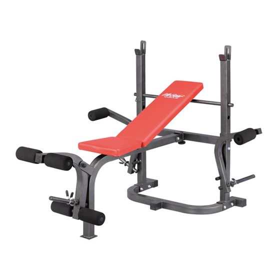
- Page 1 LifeGear F2 body/BENCH ITEM NO.: 76110 OWNER’S MANUAL IMPORTANT: Read all instructions carefully before using this product. Retain this owner’s manual for future reference. The specifications of this product may vary from this photo, subject to change without notice. 2011, July...
-
Page 2: Table Of Contents
WARM UP AND COOL DOWN ROUTINE ----------------------------------------- 13 ONE YEAR LIMITED WARRANTY LifeGear Inc. warrants to the original purchaser that this product is free from defects in material and workmanship when used for the purpose intended, under the conditions that it has been installed and operated in accordance with LifeGear's Owner's Manual. -
Page 3: Safety Instructions
SAFETY INSTRUCTIONS Basic precautions should always be followed, including the following safety instructions when using this body bench: Read all instructions before using this body bench. Read all the instructions in this manual and do warm up exercises before using this body bench. -
Page 4: Parts List
PARTS LIST Description Qty No. Description 001 Upright Beam 50x50xt1.5 2 020 Butterfly Arm Buffer Cap Ø22xØ19x48 002 Base Frame 50x50xt1.5 1 021 Leg Developer Buffer Cap Ø25 003 Cross Brace 50x50xt1.5 1 022 End Cap Ø22 004 Main Seat Support Frame 1 023 End Cap Ø25 50x50xt1.5 005 Left Butterfly Arm 50x50xt1.5... -
Page 5: Hardware Packing List
HARDWARE PACKING LIST (29) Nylon Nut M10 (30) Washer Ø6 (31) Washer Ø10 11 PCS 8 PCS 24 PCS (32) Bolt M6x35 (33) Bolt M6x40 (34) Bolt M10x25 4 PCS 4 PCS 2 PCS (35) Bolt M10x70 (36) Bolt M10x75 (37) Bolt M10x150 4 PCS 6 PCS... -
Page 6: Overview Drawing
OVERVIEW DRAWING 29 31... -
Page 7: Assembly Instructions
ASSEMBLY INSTRUCTIONS Tool: 2 Wrenches (14-17) Step 1 Attach the 50x50xt1.5 Cross Brace (3) onto the 50x50xt1.5 Upright Beams (1) with four M10x70 Bolts (35), four M10 Nylon Nuts (29), and eight Ø10 Washers (31). DO NOT fully tighten the bolts and nylon nuts. Attach the 50x50xt1.5 Base Frame (2) onto the 50x50xt1.5 Upright Beams (1) with four M10x75 Bolts (36), four M10 Nylon Nuts (29), and eight Ø10 Washers (31). - Page 8 Tool: 2 Wrenches (14-17) Step 2 Insert the Ø25x1.5x780 Backrest Adjustment Bar (8) into the one of the holes of the 50x50xt1.5 Upright Beams (1). Attach the 50x50xt1.5 Main Seat Support Frame (4) onto the 50x50xt1.5 Cross Brace (3) with one M10x75 Bolt (36), one M10 Nylon Nut (29), and two Ø10 Washers (31). Tighten bolt and nylon nut with two 14-17 Wrenches provided.
- Page 9 Tool: 2 Wrenches (14-17) 1 Wrench (14-10) Step 3 Attach the two side-holes on both 25x25xt1.5x780 Backrest Support Tubes (10) onto the 50x50xt1.5 Main Seat Support Frame (4) with one M10x150 Bolt (37), one M10 Nylon Nut (29), and two Ø10 Washers (31). Tighten bolt and nylon nut with two 14-17 Wrenches provided.
- Page 10 4 Bolts (M6x40) 4 Bolts (M6x35) 8 Washers (Ø6) ․․․․․․․․․․․․․․․․․․․․․․․․․․․․․․․․․․․․․․․ Tool: 2 Wrenches (14-17) Step 4 Attach the 50x50xt1.5-Ø25xt1.5 Leg Developer (7) onto the 50x50xt1.5 Main Seat Support Frame (4) with one M10x75 Bolt (36), one M10 Nylon Nut (29), and two Ø10 Washers (31). Tighten bolt and nylon nut with two 14-17 Wrenches provided.
- Page 11 Butterfly Arm (5) with one M10x25 Bolt (34) and one Ø10 Washer (31). Tighten bolt with the 14-17 Wrench provided. Slide the Ø70x140 Butterfly Arm Foam Roller (16) onto the B Ø25x1.5x185 Butterfly Arm Foam Roller Tube (9). Use the same procedure to install the 50x50xt1.5 Right Butterfly Arm (6) onto the 50x50xt1.5 Upright Beam (1).
-
Page 12: Adjustment
ADJUSTMENT Hook Insert the Ø25x1.5x780 Backrest Adjustment Bar (8) through into one of the selected holes on the two 50x50xt1.5 Upright Beams (1) to obtain desired incline of the Backrest Pad (12). The Hook on the Ø25x1.5x780 Backrest Adjustment Bar (8) must be hooked the 50x50xt1.5 Upright Beam (1) up before use. -
Page 13: Storage
STORAGE For your storage convenience, the bench can be folded for easy storage. Remove the M10 Lock Knob (18) from the Cross Brace (3). Then pull the Seat Support Frame (4) all the way up in the vertical position. Turn the M10 Lock Knob (18) back onto the bolt of the 50x50xt1.5 Cross Brace (3) that was removed. -
Page 14: Warm Up And Cool Down Routine
WARM UP AND COOL DOWN ROUTINE A good exercise program consists of a warm-up, aerobic exercise, and a cool down. Do the entire program at least two to three times a week, resting for a day between workouts. After several months you can increase your workouts to four or five times per week. AEROBIC EXERCISE is any sustained activity that sends oxygen to your muscles via your heart and lungs. - Page 15 SIDE STRETCHES Open your arms to the side and lift them until they are over your head. Reach your right arm as far toward the ceiling as you can for one count. Repeat this action with your left arm. QUADRICEPS STRETCH With one hand against a wall for balance, reach behind you and pull your right foot up.
- Page 16 TOE TOUCHES Slowly bend forward from your waist, letting your back and shoulders relax as you stretch toward your toes. Reach as far as you can and hold for 15 counts. HAMSTRING STRETCHES Extend your right leg. Rest the sole of your left foot against your right inner thigh.
Need help?
Do you have a question about the F2 body/BENCH and is the answer not in the manual?
Questions and answers