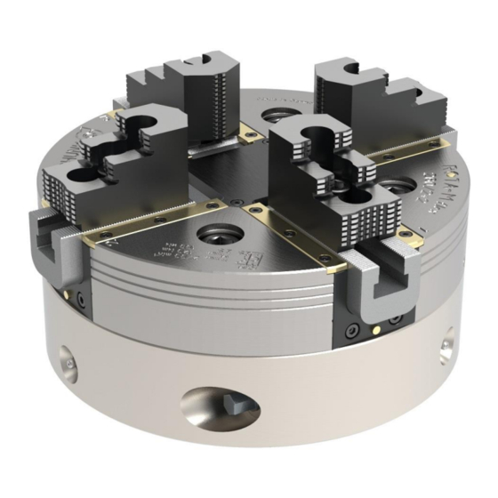
SCHUNK ROTA-M flex 2+2 Series Assembly And Operating Manual
Lathe chuck
Hide thumbs
Also See for ROTA-M flex 2+2 Series:
- Assembly and operating manual (51 pages) ,
- Assembly and operating manual (60 pages)

Related Manuals for SCHUNK ROTA-M flex 2+2 Series


Summary of Contents for SCHUNK ROTA-M flex 2+2 Series
- Page 1 Translation of Original Operating Manual Manual Lathe Chuck ROTA-M flex 2+2 Assembly and Operating Manual Superior Clamping and Gripping...
- Page 2 Imprint Copyright: This manual is protected by copyright. The author is SCHUNK GmbH & Co. KG. All rights reserved. Any reproduction, processing, distribution (making available to third parties), translation or other usage - even excerpts - of the manual is especially prohibited and requires our written approval.
-
Page 3: Table Of Contents
Table of Contents Table of Contents 1 General ........................5 1.1 About this Manual ....................5 1.1.1 Illustration of safety notes ................5 1.1.2 Applicable documents ................... 6 1.1.3 Sizes ....................... 6 1.2 Warranty ........................6 1.3 Scope of delivery ...................... 7 2 Basic safety notes ..................... - Page 4 Table of Contents 3.6 Permissible imbalance DIN ISO 21940-11 .............. 32 4 Screw tightening torques ..................32 5 Assembly ......................... 33 5.1 Installing and connecting ..................33 5.2 Testing the spindle nose and/or machine table ............ 34 5.3 Assembly ......................... 35 5.3.1 Assembly of the lathe chuck (with cylindrical recess) ........
-
Page 5: General
General General About this Manual This manual contains important information for the safe, correct use of the product. The manual is an integral part of the product and must be kept accessible by personnel at all times. Personnel must have read and understood this manual before beginning any work. -
Page 6: Applicable Documents
General 1.1.2 Applicable documents • General terms and conditions* • VDI guideline 3106 1.1.3 Sizes This manual applies to the following sizes: • ROTA-M flex 2+2 260 • ROTA-M flex 2+2 315 • ROTA-M flex 2+2 400 • ROTA-M flex 2+2 500 •... -
Page 7: Scope Of Delivery
General Scope of delivery Manual lathe chuck in the ordered variant Mounting screws (up to size 630) T-nuts with screws or 4 combi T-nuts (for variant with 60° fine serration) Assembly key Actuation key or wrench (from size 800) 1 (2) Eye bolt (from size 800) Assembly and Operating Manual... -
Page 8: Basic Safety Notes
Basic safety notes Basic safety notes Appropriate use The product is used to clamp workpieces in machine tools or assembly devices during machining. • Rotation of the lathe chuck can be initiated by the machine during machining or the lathe chuck can be at rest. The use of coolants during machining is permitted. -
Page 9: Structural Changes
• Use for stationary or rotating processes where there is no workpiece or the workpiece is not clamped. • Use of chuck jaws that have not been approved by SCHUNK (self-built, third-party products). • Removing the release mechanism from the actuation key. -
Page 10: Spare Parts
Use of unauthorized spare parts Using unauthorized spare parts can endanger personnel and damage the product or cause it to malfunction. • Use only original spare parts and spares authorized by SCHUNK. Chuck Jaws Requirements of the chuck jaws Accumulated energy can make the product unsafe and risk the danger of serious injuries and considerable material damage. -
Page 11: Ambient Conditions And Operating Conditions
• Materials used: steel alloys, elastomers, aluminum alloys, brass Safety data sheet for LINOMAX plus available at www.schunk.com Required ambient conditions and operating conditions Incorrect ambient and operating conditions can make the product unsafe, leading to the risk of serious injuries, considerable material damage and/or a significant reduction to the product's life span. -
Page 12: Personnel Qualification
Basic safety notes If the clamping force has dropped too much or if the base jaws no longer move properly, the chuck must be disassembled, cleaned, and relubricated ( 7, Page 46). Personnel qualification The following personnel qualifications are required for the various types of work on the product: Specialist personnel Specialist personnel have the specialized training, knowledge, and... -
Page 13: Personal Protective Equipment
Basic safety notes Personal protective equipment Use of personal protective equipment Personal protective equipment serves to protect staff in the event of a danger that may interfere with their health or safety at work. • When working on and with the product, observe the occupational health and safety regulations and wear the required personal protective equipment. -
Page 14: Transport
Basic safety notes 2.10 Transport Handling during transport Incorrect handling during transport can make the product unsafe and risk serious injuries and considerable material damage. • When handling heavy weights, use lifting equipment to lift the product and transport it by appropriate means. •... -
Page 15: Protection During Handling And Assembly
Basic safety notes • Disconnect power sources before installation, modification, maintenance, or calibration. Ensure that no residual energy remains in the system. • Do not reach into the open mechanism or movement area of the product during operation. 2.13.1 Protection during handling and assembly Incorrect handling and assembly Incorrect handling and assembly can make the product unsafe and pose a risk of serious injuries and considerable material damage. -
Page 16: Protection Against Dangerous Movements
Basic safety notes 2.13.3 Protection against dangerous movements Unexpected movements If the system still retains residual energy, serious injuries can be caused while working on the product. • Switch off the energy supply, ensure that no residual energy remains and secure against inadvertent reactivation. •... - Page 17 Basic safety notes DANGER Possible risk of fatal injury to operating personnel if a jaw breaks or if the chuck fails because the technical data have been exceeded and a workpiece is released or parts fly off! • The technical data specified by the manufacturer for using the lathe chuck must never be exceeded.
- Page 18 Basic safety notes CAUTION Risk of limbs being crushed when opening and closing the chuck jaws during manual loading or unloading or when exchanging moving parts. • Do not reach between the chuck jaws. • Wear protective gloves. • Follow the safety and accident prevention regulations when operating the chuck, especially when working with machine tools and other technical equipment.
-
Page 19: Technical Data
Screw tightening torques Technical data Lathe chuck data ROTA-M flex 2+2 1000 1200 Max. actuation moment [Nm] Max. clamping force [kN] Max. speed [rpm] 2700 2200 1500 1100 Overall stroke per jaw 14.5 17.8 17.8 17.8 17.8 17.8 [mm] Compensation per jaw [mm] Weight with base jaws [kg] 41.7 62.9... -
Page 20: Dimensions
Screw tightening torques Dimensions 02.00|1416054_ROTA-M2 + 2 |en-US... - Page 21 Screw tightening torques 02.00|1416054_ROTA-M2 + 2 |en-US...
- Page 22 Screw tightening torques Index 1000 1200 SV90° SV90° 90SV° SV90° SV90° module module module (60°) (60°) (60°) A [mm] 1000 1200 W [mm] 220 C [mm] 171.4 171.4 330.2 330.2 330.2 D [mm] 108.5 108.5 189.8 199.8 199.8 E [mm] F1 H7 25.5 25.5...
- Page 23 Screw tightening torques Index 800 module 2 1000 module 2 1200 module 2 60 H7 60 H7 60 H7 343.5 443.5 543.5 14.7 11.25 22.5 22.5 22.5 22 G7 22 G7 22 G7 13.5 17.5 1050 02.00|1416054_ROTA-M2 + 2 |en-US...
-
Page 24: Clamping Force Rpm Diagrams
The lathe chuck is in perfect condition and lubricated with SCHUNK LINOMAX plus special grease. If one or more of these prerequisites is modified, the graphs will no longer be valid. - Page 25 Screw tightening torques Clamping force/RPM graph for ROTA-M flex 2+2 315 Clamping force/RPM graph for ROTA-M flex 2+2 400 Clamping force/RPM graph for ROTA-M flex 2+2 500 02.00|1416054_ROTA-M2 + 2 |en-US...
- Page 26 Screw tightening torques Clamping force/RPM graph for ROTA-M flex 2+2 630 Clamping force/RPM graph for ROTA-M flex 2+2 800 Clamping force/RPM graph for ROTA-M flex 2+2 1000 02.00|1416054_ROTA-M2 + 2 |en-US...
-
Page 27: Calculating The Clamping Force And Rpm
Screw tightening torques Clamping force/RPM graph for ROTA-M flex 2+2 1200 Calculating the clamping force and RPM Missing information or specifications can be requested from the manufacturer. Legend Total centrifugal force [N] Centrifugal torque of top jaws [Kgm] Effective clamping force [N] Centrifugal torque of base jaws [Kgm] Minimum required clamping force Speed of rotation [RPM]... - Page 28 Screw tightening torques (–) for gripping from the outside inwards (+) for gripping from the inside outwards DANGER Risk to life and limb of the operating personnel and significant property damage when a certain RPM limit is exceeded! When clamping from the outside in, as the RPM increases, the effective clamping force decreases by the amount by which the centrifugal force increases (the forces are opposed).
- Page 29 Screw tightening torques NOTICE This calculated force must not be larger than the maximum clamping force ΣS engraved on the lathe chuck. See also "Lathe chuck data" table ( 3.1, Page 19) From the above formula it is evident that the sum of the effective clamping force F and the total centrifugal force F is multiplied by...
-
Page 30: Calculation Example: Required Initial Clamping Force For A Given Rpm
Screw tightening torques 3.4.2 Calculation example: required initial clamping force for a given Required initial clamping force F for a given RPM n The following data is known for the machining job: • Gripping from the outside in (application-specific) • Machining force F = 3000 N (application-specific) •... -
Page 31: Calculation Of The Permissible Rpm In Case Of A Given Initial Clamping Force
Screw tightening torques The total centrifugal force can now be calculated: Initial clamping force during shutdown that was sought: 3.4.3 Calculation of the permissible RPM in case of a given initial clamping force Calculation of the permissible RPM n in case of a given initial perm clamping force F The following formula can be used to calculate the permissible... -
Page 32: Accuracy Classes
Screw tightening torques The calculated RPM n = 1495 RPM is smaller than the perm maximum permissible RPM of the lathe chuck n = 3200 RPM (see "Lathe chuck data" table ( 3.1, Page 19)). This calculated RPM may be used. Accuracy classes Tolerances for run-out accuracy and axial run-out accuracy correspond to the Technical Supply Terms for lathe chucks as per... -
Page 33: Assembly
Assembly Assembly Installing and connecting WARNING Risk of injury due to sudden movements! If the energy supply is switched on or if residual energy is still present in the system, this can cause components to move unexpectedly, which may result in serious injuries. •... -
Page 34: Testing The Spindle Nose And/Or Machine Table
Assembly Testing the spindle nose and/or machine table Spindle nose The machine side must be aligned prior to the installation in order to achieve high run-out accuracy of the lathe chuck. To do this, check the contact surfaces on the spindle for axial and radial run- out accuracy using a dial indicator. -
Page 35: Assembly
Assembly Assembly Lathe chuck assembly 5.3.1 Assembly of the lathe chuck (with cylindrical recess) NOTE If the interface of the machine spindle and lathe chuck is identical, assembly is carried out without assembly preparation. If the interface of the machine spindle deviates from the interface of the lathe chuck, a connecting flange must be affixed before assembly. - Page 36 Assembly NOTICE Use a crane to install the chuck. Fasten the lathe chuck to the eye bolt provided for this purpose (see Fig. "Lathe chuck assembly" - C ( 5.3, Page 35)). The eye bolt must be removed prior to starting up. The eye bolt is included in the scope of delivery.
-
Page 37: Assembly Preparation For The Lathe Chuck With Reduction Or Expansion Adapter Plate
Assembly Concentricity and axial run-out tolerances Lathe chuck size Max. concentricity Max. axial run-out [mm] error [mm] error [mm] 0.03 0.02 0.04 0.06 0.03 5.3.2 Assembly preparation for the lathe chuck with reduction or expansion adapter plate If the bolt pitch circle of the machine spindle does not correspond to the bolt pitch circle of the lathe chuck, a reduction or expansion adapter plate must be used. -
Page 38: Assembly Preparation For The Lathe Chuck With Direct Mounting
Assembly 5.3.3 Assembly preparation for the lathe chuck with direct mounting If the bolt pitch circle of the short taper machine spindle is identical to that of the lathe chuck, a direct mount must be used. Fasten the direct mount to the lathe chuck prior to lathe chuck assembly. -
Page 39: Function
Function Function Function and handling The manual lathe chuck ROTA-M flex 2+2 has a centrically compensating clamping function, which enables the clamping of round, cubic and geometrically awkward workpieces. The opposite jaws move centrically towards each other. The workpiece is centered in two compensating planes that are perpendicular to each other. -
Page 40: Replacement Or Enlargement Of Jaws
Replacement or enlargement of jaws Changing the top jaws When changing the top jaws, the serration has to be cleaned and greased with SCHUNK LINOMAX plus special grease. Tighten the jaw mounting screws (screw quality 12.9) to the specified torque. -
Page 41: Clamping The Workpiece
Function Clamping the workpiece 1 Determination of the required actuation moment is based on the clamping force calculation. ( 3.4, Page 27) 2 The workpiece is clamped by twisting the spindle (item 8) using the actuation key or a torque wrench. 3 Check both stroke controls, which are located below guideways 1 and 4. -
Page 42: Compensation / Workpiece Dimensions
Function Compensation / workpiece dimensions ROTA-M flex 2+2 500-1200 Overall stroke per jaw [mm] 14.5 17.8 Compensation per jaw [mm] The compensation area of the lathe chuck is located in the center of the overall jaw stroke and is also the area within which the indicator pins are completely recessed. -
Page 43: Fixed Workpiece Stops And Stop Jaws
Function Fixed workpiece stops and stop jaws The ROTA-M flex 2+2 from size 800 offers the opportunity to realize clamping structures with one or two fixed workpiece stops through the use of fixed workpiece stops and the related stop jaws. Fixed workpiece stops and stop jaws are available as accessories. -
Page 44: Assembly Of The Locking Cover
Function 6.6.2 Assembly of the locking cover If a clamping structure is to be realized that only contains one active level of jaws (centric clamping vise and vise) using fixed workpiece stops and/or stop jaws, then it is necessary to install the locking cover: 1 Loosen the screws (item 33) and remove the cover (item 3) with the O-ring (item 37). -
Page 45: Possibilities For Clamping Structure Size 800 - 1200
Function 6.6.3 Possibilities for clamping structure size 800 - 1200 Centric-clamping devices: Each stop jaw presses the workpiece with 25% of the clamping force generated by the actuation moment. • max. actuation moment: 250 Nm • max. clamping force on the workpiece: 90 kN USE LOCKING COVER! FOR O.D. -
Page 46: Maintenance
Maintenance Maintenance Lubrication To maintain the safe function and high quality of the lathe chuck, it has to be regularly lubricated at the lubrication nipples in the chuck body. The lathe chuck must be lubricated in the open position. For optimum grease distribution, the chuck piston must travel through the entire stroke several times after lubrication. -
Page 47: Disassembling And Assembling The Chuck
Maintenance Disassembling and assembling the chuck The item numbers specified for the corresponding individual components relate to the drawing in chapter "Drawings" ( 12, Page 57). The lathe chuck can only be disassembled once it has been removed. ( 5, Page 33) 1 Loosen screws of the T-nuts and lift the lathe chuck from the machine spindle with lifting equipment. - Page 48 19 Remove the base jaws (item 2) 20 Remove the bolts (item 18) Degrease and clean all parts and check them for damage. Before assembly, grease well with LINOMAX. Only use original SCHUNK spare parts when replacing damaged parts. 02.00|1416054_ROTA-M2 + 2 |en-US...
-
Page 49: Assembling The Lathe Chuck
Maintenance Assembling the lathe chuck 1 Place the chuck body (item 1) with the guideways facing upwards 2 Slide the base jaws (item 2) into the guideways in the chuck body (item 1) CAUTION: The base jaws are numbered; install according to the numbering on the chuck body! 3 Wrap the sealing element (item 25) snugly around the projecting base jaws (item 2) and place in the gap between... - Page 50 Maintenance interlaces CAUTION: The wedge bars are numbered; install according to the numbering on the chuck body! 14 Place connecting member (item 6) on the bar of the wedge bars (item 5) 15 Place the upper drive ring (item 11) on the shaft in the lathe chuck center, thread the connecting members (item 6) into the holes.
- Page 51 Maintenance 29 Place the mounting assembly on the chuck body assembly. Observe the following points: 30 Thread the shaft of the mount into the drive rings 31 Thread the pin of the slide in the mounting assembly into the sliding block of the chuck body assembly 32 Thread the slide of the chuck body assembly into the groove of the mounting assembly 33 Fasten the mount (item 7) to the chuck body with screws...
-
Page 52: Remedies For Faults
Use correct tightening torque too high Damage to the guideways Disassemble and check the lathe chuck. Replace worn or damaged parts with SCHUNK spare parts Drive spindle damaged (due Disassemble and check the to overload) lathe chuck. Replace worn or... -
Page 53: Storage
• Dispose of the chuck's metal parts as scrap metal. Alternatively, you can return the chuck to SCHUNK for proper disposal. 02.00|1416054_ROTA-M2 + 2 |en-US... -
Page 54: Spare Parts
Spare parts Spare parts When ordering spare parts, it is imperative to state the type, size, and above all the serial number of the lathe chuck. Seals, sealing elements, screw connections, springs, bearings, screws, wiper bars and parts that come into contact with the workpiece are not covered by the warranty. - Page 55 Spare parts Item Designation Quantity Screw 28/36/44/60/ (260+315/400+500/630/800/1000/1200) 68/76 Screw Cylindrical pin O-ring O-ring Compression spring T-nut (SV90°/ SV60°) Screw Actuation key / from 800: wrench Cylindrical pin Assembly key Eye bolt 02.00|1416054_ROTA-M2 + 2 |en-US...
- Page 56 23776 T-slot nut (800/1000/1200) 12/12/16 Screw (800/1000/1200) 12/12/16 Cover (800/1000/1200) 12/12/16 Screw T-nut Screw Adapter Accessories and replacement orders at: H.-D. SCHUNK GmbH & Co. Spanntechnik KG Lothringer Str. 23 D-88512 Mengen Tel. +49–7572-7614-0 Fax +49-7572-7614-1099 info@de.schunk.com schunk.com 02.00|1416054_ROTA-M2 + 2 |en-US...
-
Page 57: Drawing
Drawing Drawing 02.00|1416054_ROTA-M2 + 2 |en-US... - Page 58 Drawing 02.00|1416054_ROTA-M2 + 2 |en-US...
-
Page 59: Declaration Of Incorporation
Declaration of Incorporation in accordance with Directive 2006/42/EC, Annex II, Part 1.B of the European Parliament and of the Council on machinery. Manufacturer/ H.-D. SCHUNK GmbH & Co. Spanntechnik KG distributor Lothringer Str. 23 D-88512 Mengen We hereby declare that on the date of the declaration the following partly completed... -
Page 60: Appendix On Declaration Of Incorporation, As Per 2006/42/Ec, Annex Ii, No. 1 B
Appendix on Declaration of Incorporation, as per 2006/42/EC, Annex II, No. 1 B Appendix on Declaration of Incorporation, as per 2006/42/EC, Annex II, No. 1 B 1. Description of the basic safety and health protection requirements, as per 2006/42/EC, annex I, that apply to and are fulfilled for the scope of the incomplete machine: Product designation Manually operated, centrically compensating 4-jaw lathe chuck... - Page 61 Appendix on Declaration of Incorporation, as per 2006/42/EC, Annex II, No. 1 B Risks from other hazards 1.5.1 Electrical energy supply 1.5.2 Static electricity 1.5.3 Non-electrical energy supply 1.5.4 Assembly errors 1.5.5 Extreme temperatures 1.45.6 Fire 1.5.7 Explosion 1.5.8 Noise 1.5.9 Vibrations 1.5.10...
Need help?
Do you have a question about the ROTA-M flex 2+2 Series and is the answer not in the manual?
Questions and answers