Sign In
Upload
Download
Table of Contents
Contents
Add to my manuals
Delete from my manuals
Share
URL of this page:
HTML Link:
Bookmark this page
Add
Manual will be automatically added to "My Manuals"
Print this page
×
Bookmark added
×
Added to my manuals
Manuals
Brands
SCHUNK Manuals
Industrial Equipment
FDB 150
Assembly and operating manual
SCHUNK FDB 150 Assembly And Operating Manual
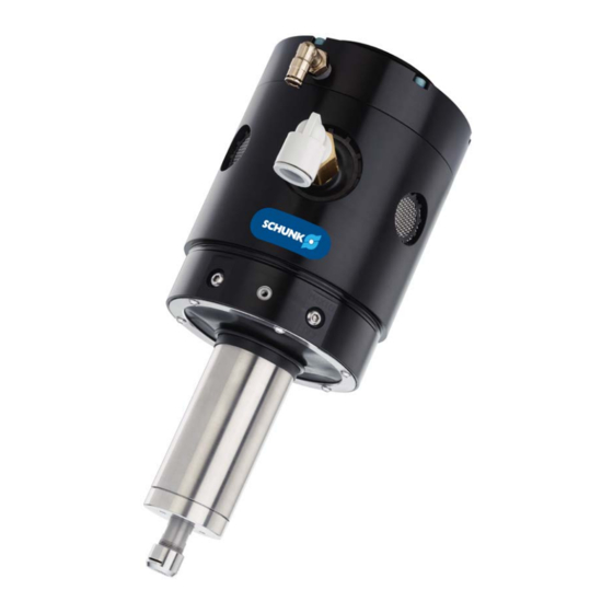
Deburring spindle
Hide thumbs
1
2
Table Of Contents
3
4
5
6
7
8
9
10
11
12
13
14
15
16
17
18
19
20
21
22
23
24
25
26
27
28
29
30
31
32
33
34
35
36
37
38
39
40
41
42
43
44
45
46
47
48
49
50
51
52
53
54
55
56
57
58
59
60
61
62
63
64
65
66
67
68
page
of
68
Go
/
68
Contents
Table of Contents
Troubleshooting
Bookmarks
Table of Contents
Table of Contents
Glossary
1 General
About this Manual
Presentation of Warning Labels
Applicable Documents
Sizes
Warranty
2 Safety
Intended Use
General Safety Guidelines
Safety Precautions
3 Product Overview
Tool Collet Systems
4 Technical Data
5 Installation
Inspection of Condition When Delivered
Unpacking and Handling
Mounting
Axial Mounting Installation
Pneumatics
Transportation and Protection During Transportation
Storage and Preventive Maintenance During Storage
6 Operation
General Precautions
Working Environment
Operational Considerations
Tool Center Point (TCP) Position and Programming
Cutter Operation and Burr Selection
Burr Selection Table
7 Troubleshooting
8 Maintenance
Recommended Spare Parts
Preventive Maintenance
Inspect Pneumatics Lines and Filter Regulator
Lubrication
Spindle Boot Inspection
Burr Inspection
Service Procedures
Burr Replacement
Air Motor Replacement
Pivot Bearing Replacement
Ring Cylinder Assembly Replacement
Spindle Boot Replacement FDB 660
9 Translation of Original Declaration of Incorporation
Advertisement
Quick Links
Download this manual
original manual
Deburring spindle
FDB 150, 300, 340, 660, 900, 1040
Assembly and operating manual
Superior Clamping and Gripping
Table of
Contents
Previous
Page
Next
Page
1
2
3
4
5
Advertisement
Table of Contents
Need help?
Do you have a question about the FDB 150 and is the answer not in the manual?
Ask a question
Questions and answers
Related Manuals for SCHUNK FDB 150
Industrial Equipment SCHUNK ROTA-S flex 550 Assembly And Operating Manual
Manual chuck (37 pages)
Industrial Equipment SCHUNK ROTA-S flex 1000 Assembly And Operating Manual
Manual chuck (37 pages)
Industrial Equipment SCHUNK ROTA-S flex 700 Assembly And Operating Manual
Manual chuck (37 pages)
Industrial Equipment SCHUNK Vario F Series Operating Manual
Collet chuck, supplement to rota thw vario (20 pages)
Industrial Equipment SCHUNK ROTA FSW Series Assembly And Operating Manual
Chuck quick-change (41 pages)
Industrial Equipment SCHUNK ROTA FSW Assembly And Operating Manual
Chuck quick-change (40 pages)
Industrial Equipment SCHUNK FDB 340 Assembly And Operating Manual
Deburring spindle (68 pages)
Industrial Equipment SCHUNK ROTA-M flex 2+2 Series Assembly And Operating Manual
Lathe chucks (51 pages)
Industrial Equipment SCHUNK ROTA-M flex 2+2 Series Assembly And Operating Manual
Lathe chuck (61 pages)
Industrial Equipment SCHUNK ROTA-M flex 2+2 Assembly And Operating Manual
(60 pages)
Industrial Equipment SCHUNK FDB Assembly And Operating Manual
Chamfering spindle (56 pages)
Industrial Equipment SCHUNK PGH 150 Operating Manual
2-finger parallel gripper (11 pages)
Industrial Equipment SCHUNK PFH 150 Assembly And Operating Manual
2-finger parallel gripper (36 pages)
Industrial Equipment SCHUNK VERO-S NSL3 Assembly And Operating Manual
Quick-change pallet system (56 pages)
Industrial Equipment SCHUNK MPG Series Assembly And Operating Manual
2-finger parallel gripper (48 pages)
Industrial Equipment SCHUNK MPG Assembly And Operating Manual
Small 2-finger parallel gripper (25 pages)
This manual is also suitable for:
Fdb 300
Fdb 340
Fdb 660
Fdb 900
Fdb 1040
Table of Contents
Print
Rename the bookmark
Delete bookmark?
Delete from my manuals?
Login
Sign In
OR
Sign in with Facebook
Sign in with Google
Upload manual
Upload from disk
Upload from URL


Need help?
Do you have a question about the FDB 150 and is the answer not in the manual?
Questions and answers