
Subscribe to Our Youtube Channel
Related Manuals for SCHUNK FDB


Summary of Contents for SCHUNK FDB
- Page 1 Translation of Original Operating Manual Assembly and Operating Manual Chamfering spindle...
- Page 2 Imprint Imprint Copyright: This manual is protected by copyright. The author is SCHUNK GmbH & Co. KG. All rights reserved. Technical changes: We reserve the right to make alterations for the purpose of technical improvement. Document number: 389072 Version: 04.00 | 30/08/2022 | en...
-
Page 3: Table Of Contents
General Precautions ................... 21 Working Environment .................. 22 Operational Considerations................ 22 Lock axis for compensation in one direction (FDB 900 / FDB 1040).... 22 Tool Center Point (TCP) Position and Programming........... 24 Cutter Operation and Burr Selection.............. 26 6.6.1 Burr Selection Table................ 26 Troubleshooting ..................... 30... - Page 4 8.3.5 Spindle Boot Replacement FDB 660 ............ 52 Transport and storage..................... 54 Transportation and Protection during Transportation........ 54 Storage and Preventive Maintenance during Storage........ 54 10 Translation of original declaration of incorporation .......... 55 04.00 | FDB | Assembly and Operating Manual | en | 389072...
-
Page 5: General
Dangers for persons! Non-observance can lead to irreversible injury and even death. CAUTION Dangers for persons! Non-observance can cause minor injuries. CAUTION Material damage! Information about avoiding material damage. 04.00 | FDB | Assembly and Operating Manual | en | 389072... -
Page 6: Definition Of Terms
• FDB 900 • FDB 1040 1.2 Warranty The warranty of the Chamfering spindle FDB is valid for 24 months. This does not apply to the air motor. The air motor is warranted for a period of 1000 hours at not lubricated operations or 12 month of operation from date of delivery from the production facility, whichever occurs first. -
Page 7: Basic Safety Notes
Flying debris can cause injury. Always use eye protection while working in the neighborhood • of the deburring tool. Never operate the FDB product without wearing eye • protection. 04.00 | FDB | Assembly and Operating Manual | en | 389072... - Page 8 Basic safety notes CAUTION Using burrs rated for less than the speed of the FDB being used may cause injury or damage equipment. Do not use burrs rated for less than the speed of the FDB • being used. Always use burrs rated for at least the speed of the FDB being •...
-
Page 9: General Safety Guidelines
The routing of pneumatic lines must minimize the possibility of stress/ strain, kinking, rupture, etc. Failure of critical pneumatic lines to function properly may result in equipment damage. 04.00 | FDB | Assembly and Operating Manual | en | 389072... -
Page 10: Product Overview
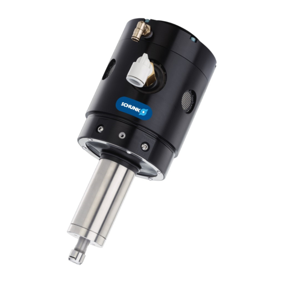
The FDB Deburring Spindle is a robust, high-speed and lightweight air turbine-driven deburring unit for deburring aluminum, plastic, steel, etc. with a robot or CNC machine. The FDB is especially suited for removal of parting lines and flash from parts. However, its flexible design allows it to be used in a wide variety of applications. -
Page 11: Tool Collet Systems
The air motor design does not allow the installation of spindle brakes or quick- change (drawbar) collet systems. 04.00 | FDB | Assembly and Operating Manual | en | 389072... -
Page 12: Technical Data
10.2 l/s (21.5 CFM) 10.2 l/s (21.5 CFM) (blocked) Noise pressure level * 78 dB(A) (without 78 dB(A) (without 78 dB(A) (without milling cutter) milling cutter) milling cutter) 04.00 | FDB | Assembly and Operating Manual | en | 389072... - Page 13 All noise emission measurements were taken under no load idle conditions without a cutting tool. Because the working environment is unknown it is impossible to predict the noise that will occur during a deburring operation. The FDB may also excite resonant frequencies on equipment to which it is mounted creating higher sound pressure levels than the unit by itself.
- Page 14 (centering) air pressure. Measurements may vary from one product to another, and should only be treated as nominal. FDB 150 Compliance Air Pressure (Bar) FDB 300/340 Compliance Air Pressure [bar] 04.00 | FDB | Assembly and Operating Manual | en | 389072...
- Page 15 The air turbine will attempt to maintain its full rated speed even under loaded conditions. However, when extremely heavy cuts are taken the motor may eventually stall. Therefore, multiple light passes are preferred over slow, heavy cuts. 04.00 | FDB | Assembly and Operating Manual | en | 389072...
-
Page 16: Installation
5 micron or better. The use of a coalescing air filter is recommended to remove all trace moisture and oil. 04.00 | FDB | Assembly and Operating Manual | en | 389072... -
Page 17: Axial Mounting Installation
FDB. SCHUINK can provide custom interface plates and adapters upon request. An optional bench mount adapter plate allows the FDB to be permanently attached to a bench or other work surface . If the FDB is permanently mounted to a work surface, the robot carries the part to be deburred to the FDB. -
Page 18: Pneumatics
6.2 bar Spindle Filter Motor Supply Air: Vent to clean, dry, Atmosphere non-lubricated 6.9 bar min. Compliance (centering) Cylinders Precision Regukator 0-4.2 bar Pneumatic connections FDB-900 and FDB-1040 04.00 | FDB | Assembly and Operating Manual | en | 389072... - Page 19 Solenoid valves are actuated from the robot or program logic controller by means of a digital output signal. 04.00 | FDB | Assembly and Operating Manual | en | 389072...
- Page 20 12]). The compliance force, air supply pressure regulator should have a (FDB 150: 1.4 - 4.2 bar / FDB 300-1040: 0-4.1 bar) range. When testing for the proper contact force, start with a very low pressure and increase slowly until the desired cut is achieved.
-
Page 21: Operation
Countersinking and other axial metal-forming processes should not be performed by the FDB. It may be dangerous to operate the FDB deburring tool for these purposes. If a failure occurs due to forces caused by improper use, hazardous situations for both personnel and equipment could be created. -
Page 22: Working Environment
Be aware of rotating parts. Use eye-protection while working around the FDB. Be aware of high sound levels. While the FDB air motor is not loud, the cutting action associated with deburring frequently is. Always use hearing protection while working in the neighborhood of the deburring cell. - Page 23 M4 x 16 mm into the threads on the housing from which the 4 hexagon socket screws M5 x 6 mm were removed. Tighten the screws to 2.82 Nm. 5. Connect all compressed air lines. 04.00 | FDB | Assembly and Operating Manual | en | 389072...
-
Page 24: Tool Center Point (Tcp) Position And Programming
The diameter of the cutter should not exceed that of the dowel pin by more than the compliance range of the FDB. 04.00 | FDB | Assembly and Operating Manual | en | 389072... - Page 25 (FBD-150) oe 0.35 bar (FDB-300/-340/-660/990/1040). When the robot path speed is increased, it is important to notice that robot may deviate from the programmed path. Verify that at 04.00 | FDB | Assembly and Operating Manual | en | 389072...
-
Page 26: Cutter Operation And Burr Selection
This can quickly load a cutter and produce unacceptable results. In general, the traverse or feed rate of the FDB will be higher for plastics to minimize this behavior. This results in larger cuts, which more effectively remove heat from the cutter-tool interface. - Page 27 Fiberglass Router, Straight, 1/8" Burr Diameter, 1/2" Burr Length, 1/8" Shank • For trimming and contour milling of all • Special cut geometry allows high glass and carbon fiber reinforced feed rates due to low cutting plastics forces 04.00 | FDB | Assembly and Operating Manual | en | 389072...
- Page 28 • Lower axial force than ADC. plastics. • Edge and surface working. • Built up Welds of high-tensile strength in mold and die making. • Higher cutting capacity than standard cuts. 04.00 | FDB | Assembly and Operating Manual | en | 389072...
- Page 29 • Rough finishing of castings. • High cutting action. • Surface working. • Non-clogging. • Weld removal. • Smaller chips, reduced slivers. • Brazed welds. • Even, smooth surfaces. 04.00 | FDB | Assembly and Operating Manual | en | 389072...
-
Page 30: Troubleshooting
Inspect burr if worn, replace } 8.3 [ / 34]. Motor bearings are worn Inspect spindle shaft, if shaft feels loose } 8.3.3 [ / or has play, replace. 45]. 04.00 | FDB | Assembly and Operating Manual | en | 389072... - Page 31 Decrease width of cut/make multiple passes } 8.3.2 [ / Air motor needs replacing Replace air motor 35]. } 8.3.2 [ / Sticking spindle Motor bearings are worn Replace air motor 35]. 04.00 | FDB | Assembly and Operating Manual | en | 389072...
-
Page 32: Maintenance
FDB in the field. For all maintenance, it is recommended that the air supply (before the solenoid valves) be disconnected. Drain any trapped air pressure in the lines. It is suggested that the air supply be “locked out”... -
Page 33: Preventive Maintenance
7/16" [11 mm] open-end wrench 9/16” [14.5 mm] open-end wrench 8.2 Preventive Maintenance The FDB is designed to provide a long life with few parts requiring regular maintenance. The preventive maintenance of the deburring tool consists of cleaning the unit and regular inspection for wear or damage of the pneumatic lines, filter element, spindle boot, and burr. -
Page 34: Spindle Boot Inspection
Spindle shaft beyond collet to and record the length of the recorded length burr extending beyond the collet nut Collet Burr Collet nut Open-end Wrench Collet nut 04.00 | FDB | Assembly and Operating Manual | en | 389072... -
Page 35: Air Motor Replacement
The air motor is replaced as a subassembly. Should the customer wish to replace the motor subassembly after the warranty period, the steps in the following chapters must be performed: 04.00 | FDB | Assembly and Operating Manual | en | 389072... - Page 36 14. Move the air motor spindle sideways in the housing toward where the fitting was removed in the previous step and pull the motor assembly from the unit. 04.00 | FDB | Assembly and Operating Manual | en | 389072...
- Page 37 Continue to slide the motor assembly into the housing until the bearing (without the extended inner race) in the gimbal ring aligns with the threaded hole on the housing flat surface. 04.00 | FDB | Assembly and Operating Manual | en | 389072...
- Page 38 5. Remove the brass plug or hex socket screw from the center of the deburring unit's rear plate. 04.00 | FDB | Assembly and Operating Manual | en | 389072...
- Page 39 1. Remove and/or lock-out the spindle motor air supply for safety. 2. Disconnect the air hose from the spindle supply fitting and the compliance air fitting. 3. Remove the deburring tool from the robot or work location. 04.00 | FDB | Assembly and Operating Manual | en | 389072...
- Page 40 14. Using a 1.3 mm Allen wrench inserted into the side hole of the threaded bushing, turn the bushing in toward the gimbal ring. 04.00 | FDB | Assembly and Operating Manual | en | 389072...
- Page 41 22. Using a 1.3 mm Allen wrench inserted into the side hole of the threaded bushing, turn the bushing in toward the motor ring. 04.00 | FDB | Assembly and Operating Manual | en | 389072...
- Page 42 1/6 of a turn (one through hole). 29. Using a 2 mm Allen wrench, tighten the M4 set screw at the bottom of the motor ring to 2.82 Nm. 04.00 | FDB | Assembly and Operating Manual | en | 389072...
- Page 43 1/6 of a turn (one through hole). 34. Using a 2 mm Allen wrench, tighten the 2 M4 set screws at the bottom of the gimbal ring to 2.82 Nm. 04.00 | FDB | Assembly and Operating Manual | en | 389072...
- Page 44 41. Assemble the O-ring over the disk boot, it will seat in the groove in the air motor assembly. 42. Assemble the new internal retaining ring and rubber disk to the spindle supply fitting as shown in the figure. 04.00 | FDB | Assembly and Operating Manual | en | 389072...
-
Page 45: Pivot Bearing Replacement
There are two bearings in the outer gimbal ring and two bearings in the black anodized ring on the motor subassembly. Should the bearings require replacement refer to the steps below: 04.00 | FDB | Assembly and Operating Manual | en | 389072... - Page 46 36]. 8.3.3.2 Pivot Bearing Replacement FDB 300 / FDB 340 Early FDB units can be identified by their lack of radial and axial tapped holes for the pivot bearing keying dowel (see Figure). During maintenance of these units the customer should replace the entire rear housing assembly to upgrade the deburring tool.
- Page 47 3. Remove the large clamping washer which rests on top of the pivot bearing. 4. Locate and loosen the radially tapped bearing preload set screw in the rear housing. 04.00 | FDB | Assembly and Operating Manual | en | 389072...
- Page 48 Tighten all socket head cap screws securely. Do not tighten the set screws further. 04.00 | FDB | Assembly and Operating Manual | en | 389072...
-
Page 49: Ring Cylinder Assembly Replacement
8. Install the rear housing to the front housing assembly and secure with six socket head cap screws and torque to 1.35 Nm. 04.00 | FDB | Assembly and Operating Manual | en | 389072... - Page 50 Use hand pressure and a flat plate to press the ring cylinder ✓ into the housing and past the retaining ring groove. 04.00 | FDB | Assembly and Operating Manual | en | 389072...
- Page 51 IMPORTANT! Be sure O-ring stay properly seated into grooves. Tighten to 2.82 Nm. 13. Assemble the rear housing to the front housing. 04.00 | FDB | Assembly and Operating Manual | en | 389072...
-
Page 52: Spindle Boot Replacement Fdb 660
9. Apply Loctite 222 to the threads of the M3 socket button head cap screws. 04.00 | FDB | Assembly and Operating Manual | en | 389072... - Page 53 12. Install the deburring tool to the robot or work location. 13. Connect the air hose to the spindle supply fitting and the compliance air fitting. 14. Apply and/or unlock the spindle motor air supply. 04.00 | FDB | Assembly and Operating Manual | en | 389072...
-
Page 54: Transport And Storage
9.2 Storage and Preventive Maintenance during Storage The FDB should be stored in its crate when it is not in use. The FDB should also be stored in a dry place. -
Page 55: Translation Of Original Declaration Of Incorporation
Person authorized to compile the technical documentation: Robert Leuthner, Address: see manufacturer's address Lauffen/Neckar, August 2022 p.p. Ralf Winkler; Head of Technology & Engineering, Mechanics Gripping Systems 04.00 | FDB | Assembly and Operating Manual | en | 389072... - Page 56 Translation of Original Operating Manual SCHUNK GmbH & Co. KG Clamping and gripping technology Bahnhofstr. 106 - 134 D-74348 Lauffen/Neckar Tel. +49-7133-103-0 Fax +49-7133-103-2399 info@de.schunk.com schunk.com Folgen Sie uns I Follow us...
Need help?
Do you have a question about the FDB and is the answer not in the manual?
Questions and answers