Table of Contents
Advertisement
Quick Links
Advertisement
Table of Contents

Related Manuals for DMP Electronics 734INT


Summary of Contents for DMP Electronics 734INT
- Page 1 734INT Access Control Module INSTALLATION AND PROGRAMMING GUIDE...
-
Page 3: Table Of Contents
TABLE OF CONTENTS About the 734INT ........1 Program the Panel ........17 Power Supply ............1 Device Setup ............17 Zone Terminals ............1 Device Number ..............17 Annunciators ............1 Device Name ............... 17 Indicator LEDs ............1 Device Type .................18... - Page 4 Keypad Bus Wiring Specifications ..32 Public Card Formats ........33 International Certifications ....34 Intertek (ETL) Listed ........34 Product Specifications ......36 Readers and Credentials ......37...
-
Page 5: About The 734Int
ABOUT THE 734INT The 734INT Access Control Module allows you to use the powerful, built in access control capability of DMP Panels using smartcard, proximity, mag stripe, or biometric readers, or other compatible authentication devices. The 734INT includes the following features:... -
Page 6: Form C Relay
The keypad out (KYPD OUT) connection Programming Connection receives and transmits data out to other keypads or modules. Install a The 734INT also provides a keypad dual connector four‑position harness programming connection that allows to allow daisy chain connection to... -
Page 7: Pcb Features
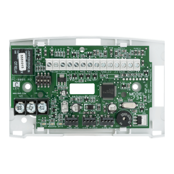
AX-Bus Piezo Piezo – RELAY WIEGAND DATA PROG KYPD IN KYPD OUT READ LED XMT LED To Other Keypad Keypad Bus Programming or AX-Bus Indicator Header LEDs Figure 1: PCB Features Digital Monitoring Products, Inc. 734INT Installation and Programming Guide... -
Page 8: Install The 734Int
The module comes in a high‑impact plastic housing that you can mount directly to a wall, backboard, or other flat surface. For easy installation, the back and ends of the 734INT housing have wire entrances. The back also contains multiple mounting holes that allow you to mount the module on a single‑gang switch box. -
Page 9: Wire The Access Control Lock
Wire the Access Control Lock The 734INT provides a Form C (SPDT) relay for controlling locks and other electronically‑controlled barriers. The three relay terminals marked NO C NC allow you to connect the device wiring to the relay for module control. - Page 10 Install a dual‑connector harness to allow connection to other devices up to the maximum number of devices supported. When the 734INT is powered from 24 VDC, do not connect devices to KYPD OUT header. Status LEDs The 734INT board contains three status LEDs.
-
Page 11: Isolation Relay (Optional)
M a g n e t i c L o c k Mag Lock Normally Open Supply – Normally Closed – – – – Figure 5: Magnetic Lock with an Isolation Figure 6: Door Strike with an Isolation Relay Relay Digital Monitoring Products, Inc. 734INT Installation and Programming Guide... -
Page 12: Install The 333 Suppressor
Install the 333 Suppressor Use the included 333 suppressor with 734INT Interface Module the 734INT to suppress any surges caused by energizing a magnetic lock Piezo or door strike. – PROG KYPD IN KYPD OUT RELAY WIEGAND DATA READ LED XMT LED Install the 333 across the 734INT C... -
Page 13: Wire The Zone Terminals
Use the supplied 311 1k Ohm End‑of‑Line (EOL) resistors on each zone. Refer to the panel programming guide for programming instructions. See Table 1 and Figure 8 for more information on wiring the zone terminals. Digital Monitoring Products, Inc. 734INT Installation and Programming Guide... - Page 14 Zone 3 can also Zone 2 be wired normally closed with an Zone 3 in-line 1k Ohm resistor Zone 4 RED WHTGRN BLK Z2 Z3 Z4+ Z4– Figure 8: Zone Terminal Wiring 734INT Installation and Programming Guide Digital Monitoring Products, Inc.
-
Page 15: Connect A Wiegand Card Reader
Connect a Wiegand Card Reader The 734INT provides direct 12/24 VDC, 200 mA output to the reader on the Red terminal connection. Figure 9 shows a reader with wire colors RED, WHT, GRN, and BLK connecting to Terminals 1, 2, 3, and 4. - Page 16 ALL SYSTEM ON. Connect a wire from the AS Terminal to an armed status indicator. Caution: Status indicator outputs support a maximum of 100 mA per terminal. Exceeding the maximum rating on LC, RA, or AS terminals can damage equipment. 734INT Installation and Programming Guide Digital Monitoring Products, Inc.
- Page 17 Wiegand Card Reader Yellow Orange or Brown Black (GND) Green (Data 0) White (Data 1) Red (12/24VDC) RED WHT GRN BLK Z4+ Z4– Figure 9: Card Reader Wiring Digital Monitoring Products, Inc. 734INT Installation and Programming Guide...
-
Page 18: Set The 734Int Address
Set the 734INT Address To set the 734INT address, move the DIP switches on the PCB to the appropriate positions. See the following sections, Figure 10, and Table 2 to determine how to set Keypad Bus or AX‑Bus addresses. Keypad Bus Addresses Explained Each Keypad Bus address can accommodate one door output and four expansion zones. - Page 19 Figure 10: Keypad/AX Bus Addresses Digital Monitoring Products, Inc. 734INT Installation and Programming Guide...
- Page 20 131‑134 549‑552 649‑652 749‑752 849‑852 949‑952 141‑144 553‑556 653‑656 753‑756 853‑856 953‑956 151‑154 557‑560 657‑660 757‑760 857‑860 957‑960 161‑164 561‑564 661‑664 761‑764 861‑864 961‑964 Table 2: Device Addresses and 734INT Zone Numbers 734INT Installation and Programming Guide Digital Monitoring Products, Inc.
-
Page 21: Program The Panel
Set the module’s address. For information about valid DEVICE NO: ‑ addresses, refer to Table 2. Device Name DEVICE SETUP Press any select area or top row key, then enter a name for *UNUSED* the module. Digital Monitoring Products, Inc. 734INT Installation and Programming Guide... -
Page 22: Device Type
AX‑BUS. Press any select area or top row key to display available options. Configure additional options as needed. To configure specific options for the module locally, do not program CARD OPTIONS or 734 OPTIONS in Device Setup. 734INT Installation and Programming Guide Digital Monitoring Products, Inc. -
Page 23: Program The 734Int
PROGRAM THE 734INT When you program a 734INT, you can use a keypad connected to the 734INT programming header and set to address 1. For 12 V applications, connect the keypad to the module using a Model 330 4‑wire harness. For 24 V applications, connect the keypad to the module using a Model 330‑24 4‑wire programming harness with in‑line resistor. -
Page 24: Programmer Menu
PROGRAMMER MENU 734INT PROGRAMMING When you connect the keypad to the 734INT module, the VER VVV MM/DD/YY version number and release date display. Press CMD to advance to Initialization Options. INITIALIZATION OPTIONS INITIALIZE ALL? These options can set the 734INT module’s programming NO YES memory back to factory defaults. -
Page 25: Access Options
NO YES NO allows standard zone operation on zone 2. The default is If the door being released by the 734INT module is protected (contact installed), a programmable bypass entry/exit timer can be provided by connecting its contact wiring to module zone 2. - Page 26 Selecting NO leaves the relay on when zone 2 changes state. Turning off the relay allows a long strike time to be automatically ended upon zone 2 change and relocks the door. The default is NO. 734INT Installation and Programming Guide Digital Monitoring Products, Inc.
-
Page 27: Activate Zone 3 Request To Exit
Activate Bypass Only Wire zone 3 as normally closed with an in‑line 1k Ohm resistor. When zone 3 opens from a normal state, only a bypass occurs and the onboard relay does not activate. Digital Monitoring Products, Inc. 734INT Installation and Programming Guide... -
Page 28: Activate Onboard Speaker
The door strike relay is activated for the length of time programmed in ZN 3 REX TIME. No user code information is sent to the panel. The menu advances to “No Communication with Panel”. The default card format is DMP. 734INT Installation and Programming Guide Digital Monitoring Products, Inc. - Page 29 See “Public Card Formats” for some publicly available card formats that can be used with the 734. Other private or custom formats may also be compatible. Please contact the credential supplier or manufacturer for the bit structure. Digital Monitoring Products, Inc. 734INT Installation and Programming Guide...
- Page 30 Position = 1 Position = 9 Received Received Length = 8 Length = 16 Position = 25 Position = 0 Example: Wiegand Code Length = 26 bits Figure 12: Wiegand Data Stream Bit Location 734INT Installation and Programming Guide Digital Monitoring Products, Inc.
- Page 31 0‑255. Press CMD to save. Default is 9. Press select area 4 to clear the user code length and enter a number between 16‑64. Press CMD to save. Default is 16. Digital Monitoring Products, Inc. 734INT Installation and Programming Guide...
-
Page 32: Require Site Code
In the keypad display, enter site code 1 and press CMD. The display will ask for site code 2 followed by site code 3 and so on. When you have selected the site code you want to change, press CMD. 734INT Installation and Programming Guide Digital Monitoring Products, Inc. -
Page 33: Number Of User Code Digits
Number of User Code Digits NO OF USER CODE The 734INT module recognizes user codes from 4‑12 digits DIGITS: long. Press any top row select key or area to enter a user code digit length. This number must match the user code number length being programmed in the panel. -
Page 34: No Communication With Panel
Press CMD to display additional actions. Press the first LAST select key or area to choose LAST (Keep Last State). The relay remains in the same state and does not change when communication is lost. 734INT Installation and Programming Guide Digital Monitoring Products, Inc. -
Page 35: Remove Keypad
After five seconds, the piezo begins sounding continually. To disconnect the keypad and silence the piezo, remove the keypad harness. Digital Monitoring Products, Inc. 734INT Installation and Programming Guide... -
Page 36: Keypad Bus Wiring Specifications
When voltage is too low, the devices cannot operate properly. For additional information refer to the panel’s Installation Guide or the 710 Installation Sheet (LT‑0310). 734INT Installation and Programming Guide Digital Monitoring Products, Inc. -
Page 37: Public Card Formats
Code Position Length Position Length Digits Length H10301 26 bit H10302 37 bit w/o FAC H10304 37 bit w/ FAC Farpointe 39 bit Corporate 1000 35 bit Corporate 1000 48 bit Digital Monitoring Products, Inc. 734INT Installation and Programming Guide... -
Page 38: International Certifications
Alarm systems. Intrusion and hold‑up systems. System requirements. EN 50131‑3:2009 Alarm systems. Intrusion and hold‑up systems. Control and indicating equipment. EN 60839‑11‑1:2013 Alarm and electronic security systems. Electronic access control systems. System and components requirements. 734INT Installation and Programming Guide Digital Monitoring Products, Inc. - Page 39 Part 3‑3: Limits ‑ Limitation of voltage changes, voltage fluctuations and flicker in public low‑voltage supply systems, for equipment with rated current ≤16 A per phase and not subject to conditional connection. EN 61000‑6‑4:2007 Emission standard for industrial environments Digital Monitoring Products, Inc. 734INT Installation and Programming Guide...
-
Page 40: Product Specifications
260 mA (Includes 200 mA for proximity reader) Form C Relay 35 mA at 12/24 VDC Zones 5 VDC, 2 mA max Dimensions 11.43W x 7H x 4.45D cm 4.5W x 2.75H x 1.75D in Weight 0.16 kg (5.6 oz) 734INT Installation and Programming Guide Digital Monitoring Products, Inc. -
Page 41: Readers And Credentials
ProxKey III® access device ProxPoint Plus® proximity PP‑6005B 1351 ProxPass® reader ProxPro® proximity reader with PR‑5355 1386 ISOProx II® card keypad PR‑5455 ProxPro® II proximity reader TL‑5395 Thinline II® proximity reader Digital Monitoring Products, Inc. 734INT Installation and Programming Guide... - Page 42 Delta3* Mullion mount smartcard reader MIFARE® DESFire® EV2 smartcard Delta5* Single gang box mount CSK‑2 MIFARE® DESFire® EV2 keyfob smartcard reader smartcard Delta6.4* Smartcard reader with keypad CSR‑35P Bluetooth smartcard reader 734INT Installation and Programming Guide Digital Monitoring Products, Inc.
- Page 44 LT-0737INT 20314 1.01 © 2020 Digital Monitoring Products, Inc.
Need help?
Do you have a question about the 734INT and is the answer not in the manual?
Questions and answers