Table of Contents
Advertisement
Quick Links
Advertisement
Table of Contents

Related Manuals for DMP Electronics 734N Series


Summary of Contents for DMP Electronics 734N Series
- Page 1 734N Series Wiegand Interface Modules INSTALLATION AND PROGRAMMING GUIDE...
-
Page 3: Table Of Contents
TABLE OF CONTENTS About the 734N Series ......1 Program the 734N Series Module ..19 Power Supply ............1 Version Display ...........20 Zone Terminals ............1 Zone Status Display..........20 Annunciators ............1 Diagnostic: Menu ..........20 Indicator LEDs ............2 Connect Status ............ - Page 4 Site Code Position and Length ....32 User Code Position and Length ....32 Require Site Code ..........33 Site Code ..............33 Number of User Code Digits ......34 No Communication with Panel ....35 Stop ...............36 Public Card Formats ........37 734N Series Network Specifications ..38...
-
Page 5: About The 734N Series
Warning: To avoid the risk of also connect a variety of switched ground equipment damage, do not exceed annunciators to the module for remote 750 mA total output current for zones annunciation. connected to the module. Digital Monitoring Products, Inc. 734N Series Installation and Programming Guide... -
Page 6: Indicator Leds
Indicator LEDs 734N Series modules provide three indicator LEDs. The red LED turns on for the same duration as the door strike relay. The yellow LED turns on for one second to indicate receipt of a valid Wiegand input. The green LED indicates that data is being sent to the panel. -
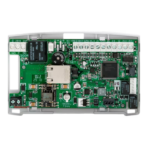
Page 7: Pcb Features
PCB FEATURES Wiegand Piezo Inputs Zones Door Relay Reset Header Status Indicator Indicator LEDs Outputs Output 2 Network Connection Output 1 Input Keypad Programming Header Figure 1: PCB Features Digital Monitoring Products, Inc. 734N Series Installation and Programming Guide... -
Page 8: Install The 734N Series Module
Insert the included screws in the desired mounting hole locations and tighten them to secure the housing to the surface. Reinstall the PCB in the housing base. Figure 2: Mounting Hole Locations 734N Series Installation and Programming Guide Digital Monitoring Products, Inc. -
Page 9: Wire The Electronic Lock
When the 734N Series module is powered with a 12/24 V power supply, the device can power an electric strike, up to 750 mA. See Figures 3 and 4 for typical magnetic lock and door strike wiring. - Page 10 12/24 VDC Suppressor – 12/24 VDC Power Supply Power Supply Magnetic Door Lock Model 333 DC Door Strike Suppressor Figure 3: Typical Magnetic Lock Wiring Figure 4: Typical Door Strike Wiring 734N Series Installation and Programming Guide Digital Monitoring Products, Inc.
- Page 11 Card Reader RED WHT GRN BLK Z1 Z4+ Z4– Door Strike POE Switch or Injector Figure 5: Typical Door Strike Wiring with POE (734N‑POE only) Digital Monitoring Products, Inc. 734N Series Installation and Programming Guide...
-
Page 12: Isolation Relay (Optional)
Interface Interface Suppressor Suppressor Module Module DC Input DC Input 12/24VDC 12/24VDC Power Power Supply Supply Figure 7: Door Strike with an Figure 6: Magnetic Lock with an Isolation Relay Isolation Relay 734N Series Installation and Programming Guide Digital Monitoring Products, Inc. -
Page 13: Install The 333 Suppressor
Install the 333 Suppressor Use the included 333 suppressor with the 734N Series module to suppress any surges caused by energizing a magnetic lock or door strike. Install the 333 across the 734N C (common) and NO (normally open) or NC (normally closed) terminals. -
Page 14: Wire The Zone Terminals
If the door is still open at the end of the second timer, Aux Output 2 is turned on. Aux Outputs 1 and 2 turn off when the door contact is closed. Use the Model 431 Relay Harness for connection of Output 1 and Output 2. 734N Series Installation and Programming Guide Digital Monitoring Products, Inc. - Page 15 1K EOL be wired normally closed with an Zone 3 1K EOL in-line 1K Ohm resistor 1K EOL Zone 4 RED WHT GRN BLK Z4+ Z4– Figure 9: Zone Terminal Wiring Digital Monitoring Products, Inc. 734N Series Installation and Programming Guide...
-
Page 16: Connect A Card Reader
Connect a Card Reader The 734N Series module provides direct 12/24 VDC, 200 mA output to the reader on the Red terminal connection. Figure 10 shows a reader with wire colors RED, WHT, GRN, and BLK connecting to terminals 1, 2, 3, and 4. - Page 17 SYSTEM ON or ALL SYSTEM ON. Connect a wire from the AS Terminal to an armed status indicator. Digital Monitoring Products, Inc. 734N Series Installation and Programming Guide...
- Page 18 Wiegand Card Reader Yellow Orange/Brown Black (GND) Green (Data 0) White (Data 1) Red (12/24VDC) RED WHT GRN BLK Z1 Z4+ Z4– Figure 10: Card Reader Wiring 734N Series Installation and Programming Guide Digital Monitoring Products, Inc.
-
Page 19: Network Connection
Network Connection Connect an IP network cable from the LAN/WAN connection to the 734N Network connector. The 734N Series module communicates AES encrypted TCP with panels that have network installed. Two LEDs are located on the Ethernet jack. • The green LED indicates that data is being sent to the panel •... -
Page 20: Set The 734N Address
DMP XR550 panels are capable of access control expansion using any of the five AX/LX‑Bus headers (AX/LX500, 600, 700, 800, and 900). An AX‑Bus address can accommodate 1 door output and 1 expansion zone. Because the 734N Series module has a built‑in 4‑zone expander, 3 extra zones must be mapped to the 734N. - Page 21 549‑552 649‑652 749‑752 849‑852 949‑952 141‑144 553‑556 653‑656 753‑756 853‑856 953‑956 151‑154 557‑560 657‑660 757‑760 857‑860 957‑960 161‑164 561‑564 661‑664 761‑764 861‑864 961‑964 Table 1: Device Addresses and 734N Zone Numbers Digital Monitoring Products, Inc. 734N Series Installation and Programming Guide...
-
Page 22: Connect The Power Supply
Use 22 AWG wire to connect the DC power terminal block on the device to the DC power terminal on the 505‑12 power supply PCB. Connect the transformer to an unswitched 120 VAC 1.5 Amp power source. 734N Series Installation and Programming Guide Digital Monitoring Products, Inc. -
Page 23: Program The 734N Series Module
PROGRAM THE 734N SERIES MODULE When you program the 734N Series module, you must use a keypad connected to the programming header and set to address 1. For 12 V applications, connect the keypad to the module using a Model 330 4‑wire harness. For 24 V applications, connect the keypad to the module using a Model 330‑24 4‑wire programming harness with in‑line resistor. -
Page 24: Version Display
CMD. 734N ZONE: 2 ‑OPEN 734N ZONE: 3 ‑SHORT Diagnostic: Menu Select YES to display Panel Communication Connect Status. MENU? NO YES Select NO to return to Version Display. 734N Series Installation and Programming Guide Digital Monitoring Products, Inc. -
Page 25: Connect Status
Duplicate Device: There is another device on the network CONNECT STATUS with the same device number. DUPLICATE DEVICE Transmit Time: The speed of the last transmission and CONNECT STATUS acknowledgement in milliseconds. XMIT TIME XXX mS Digital Monitoring Products, Inc. 734N Series Installation and Programming Guide... -
Page 26: Programming Menu
Press CMD to enter programming and display initialization PROGRAMMER options. Initialization Options 734N These options set the 734N Series module programming INITIALIZATION memory back to factory defaults. Press any select key or area to enter the initialization menu. Initialization: Communication... -
Page 27: Initialization: Access
Press the back arrow to display the 734N Initialization menu. 734N Device Number 734N DEVICE NO: Enter a device number from 2 ‑16 for the 734N Series module. This device number must also be programmed in the panel. Default is 7. -
Page 28: Dhcp
Note: This IP address must match the address programmed in the panel at the Local IP Address option in Network Options. The DHCP programming in the panel must be set to NO. 734N Series Installation and Programming Guide Digital Monitoring Products, Inc. -
Page 29: Panel Ip Port
Press any select key or area to enter the Access Options ACCESS OPTIONS menu. Press CMD to advance to the Stop options. Press the back arrow to display the Communication menu. Digital Monitoring Products, Inc. 734N Series Installation and Programming Guide... -
Page 30: Activate Zone 2 Bypass
BYPASS? NO YES NO allows standard zone operation on zone 2. The default is If the door being released by the 734N Series module is protected (contact installed), a programmable bypass entry/exit timer can be provided by connecting its contact wiring to the 734N Series module zone 2. When the onboard Form C relay activates and the user opens the door connected to zone 2, the zone is delayed for the number of... -
Page 31: Zone 2 Bypass Time
Selecting NO leaves the relay on when zone 2 changes state. Turning off the relay allows a long strike time to be automatically ended upon zone 2 change and relocks the door. The default is NO. Digital Monitoring Products, Inc. 734N Series Installation and Programming Guide... -
Page 32: Activate Zone 3 Request To Exit
Activate Bypass Only Wire zone 3 as normally closed with an in‑line 1K Ohm resistor. When zone 3 opens from a normal state, only a bypass occurs: the onboard relay does not activate. 734N Series Installation and Programming Guide Digital Monitoring Products, Inc. -
Page 33: Zone 3 Rex Strike Time
ZN 3 REX TIME. No user code information is sent to the panel. The menu advances to NO COMM WITH PNL. The default card format is DMP. Digital Monitoring Products, Inc. 734N Series Installation and Programming Guide... -
Page 34: Custom Card Definitions
Note: If you select slot 1 and you are upgrading from XR panel version 182 or earlier, FORMAT NAME will automatically be named SINGLE CARD FORMAT and WIEGAND CODE LENGTH will default to 45. 734N Series Installation and Programming Guide Digital Monitoring Products, Inc. -
Page 35: Format Name
Position = 9 Received Length = 8 Length = 16 Position = 25 Position = 0 In this example the Wiegand Code Length = 26 bits. Figure 12: Wiegand Data Stream Bit Location Digital Monitoring Products, Inc. 734N Series Installation and Programming Guide... -
Page 36: Site Code Position And Length
0‑255. Press CMD to save. Default is 9. Press select area 4 to clear the user code length and enter a number between 16‑64. Press CMD to save. Default is 16. 734N Series Installation and Programming Guide Digital Monitoring Products, Inc. -
Page 37: Require Site Code
In the keypad display, enter site code 1 and press CMD. The display will ask for site code 2 followed by site code 3 and so on. When you have selected the site code you want to change, press CMD. Digital Monitoring Products, Inc. 734N Series Installation and Programming Guide... -
Page 38: Number Of User Code Digits
All bits are read and converted into a decimal number string. The number string is left padded with 0 (zero) if needed for long user code lengths. Example: # decoded 1234567 10 digits 0001234567 4 digits 4567 734N Series Installation and Programming Guide Digital Monitoring Products, Inc. -
Page 39: No Communication With Panel
Press the first select key or area to choose LAST (Keep Last NO COMM WITH PNL State). The relay remains in the same state and does not LAST change when communication is lost. Digital Monitoring Products, Inc. 734N Series Installation and Programming Guide... -
Page 40: Stop
Press any select key to initiate the stop routine. When STOP programming is saved successfully, the version number displays. Remove the keypad harness to disconnect the keypad from the module. 734N Series Installation and Programming Guide Digital Monitoring Products, Inc. -
Page 41: Public Card Formats
FORMAT CODE CODE CODE CODE CODE CODE LENGTH POSITION LENGTH POSITION LENGTH DIGITS H10301 26 BIT H10302 37 BIT W/FAC H10304 37 BIT W/O FAC FARPOINTE 39 BIT CORPORATE 1000 35 BIT CORPORATE 1000 48 BIT Digital Monitoring Products, Inc. 734N Series Installation and Programming Guide... -
Page 42: Series Network Specifications
734N SERIES NETWORK SPECIFICATIONS The 734N Series was designed to have minimum impact on network performance. The modules are supervised in the panel by exchanging two data packets every five seconds. The payload of the data packets exchanged between the XR150/XR550 Series and the modules is a very small 18 bytes. - Page 43 A pair of supervision packets are sent every 5 seconds. ‑ The payload for each packet is 18 bytes and the total traffic, including overhead, is approximately 2 kilobytes per minute for each 734N Series module. ‑ Non‑Supervision messages have a payload range of 18‑50 bytes.
-
Page 44: Compliance Listing Specifications
POE power to be supplied by a UL 294 Listed, power limited, injector providing 50‑57 VDC and 30.0 W for maximum output (POE+). POE power to be supplied by a UL 294 Listed POE+ Midspan or Endspan providing 44‑57 VDC and 30 W for maximum output. 734N Series Installation and Programming Guide Digital Monitoring Products, Inc. - Page 45 (for example, Alternative A or Alternative B or both), and the maximum power class supported by the PSE. The 734N‑POE is compatible with the Altronix Netway 1. Figure 13: Cat 5 568‑B Wiring Digital Monitoring Products, Inc. 734N Series Installation and Programming Guide...
-
Page 46: Ulc Commercial Burglary (Xr150/Xr550 Series Panels)
The 734N Access Control features have not been investigated by ULC. The 734N zones can be used in a Low Risk application. For Medium or High Risk applications, refer to the Dual Zone Protection diagram in the XR150/XR550 Canadian Installation Guide. 734N Series Installation and Programming Guide Digital Monitoring Products, Inc. -
Page 47: Certifications
Destructive Attack, Line Security, and Standby Power Level IV Endurance ANSI/UL 609 Local Burglar Alarm Units And Systems ANSI/UL 1076 Proprietary Burglar Alarm Units And Systems ANSI/UL 1610 Central Station Burglar‑Alarm Units Digital Monitoring Products, Inc. 734N Series Installation and Programming Guide... -
Page 48: Product Specifications
When powered from POE Standby 243 mA (includes 200 mA for proximity reader) +1.6 mA per active zone Alarm 273 mA (includes 200 mA for proximity reader) +10 mA with Annunciator ON +2 mA per faulted zone 734N Series Installation and Programming Guide Digital Monitoring Products, Inc. - Page 49 Maximum Power Draw (POE) 12.95 W Total Available Output Current 750 mA Zones 5 VDC, 2 mA max Dimensions 4.5 W x 2.75 H x 1.75 D in 11.43 W x 7 H x 4.45 D cm Weight 8 oz 0.23 kg Digital Monitoring Products, Inc. 734N Series Installation and Programming Guide...
-
Page 50: Readers And Credentials
PROXPOINT® PLUS 1346 PROXKEY III® ACCESS PROXIMITY READER DEVICE PP‑5355 PROXPRO PROXIMITY 1351 PROXPASS® READER WITH KEYPAD PR‑5455 PROXPRO® II PROXIMITY 1386 ISOPROX II® CARD READER TL‑5395 THINLINE II® PROXIMITY READER 734N Series Installation and Programming Guide Digital Monitoring Products, Inc. - Page 51 FARPOINTE IMAGEABLE READER SMARTCARD DELTA5.3 FARPOINTE SMARTCARD FARPOINTE READER MIFARE® DESFIRE® EV1 SMARTCARD DELTA6.4 FARPOINTE SMARTCARD READER DK1‑3 FARPOINTE KEY FOB SMARTCARD *Delta Proximity Readers and Credentials not evaluated by UL. Digital Monitoring Products, Inc. 734N Series Installation and Programming Guide...
- Page 52 LT-1197 19345 1.04 © 2019 Digital Monitoring Products, Inc.
Need help?
Do you have a question about the 734N Series and is the answer not in the manual?
Questions and answers