DMP Electronics 734 Installation And Programming Manual
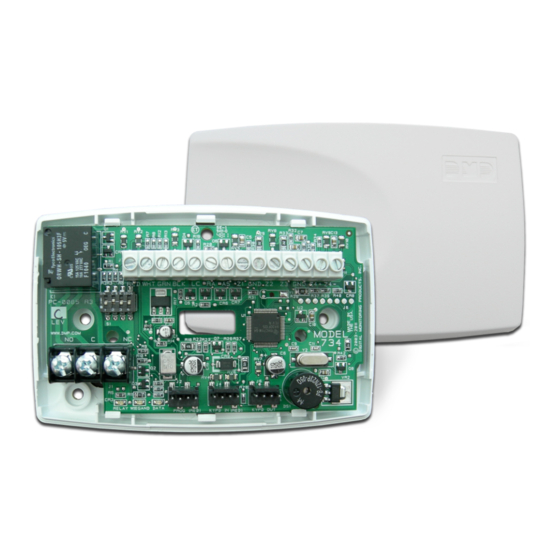
Access control module
Hide thumbs
Also See for 734:
- Installation and programming manual (44 pages) ,
- Installation sheet (10 pages) ,
- Quick start manual (2 pages)
Table of Contents
Advertisement
Quick Links
Advertisement
Table of Contents

Related Manuals for DMP Electronics 734


Summary of Contents for DMP Electronics 734
- Page 1 INSTALLATION AND PROGRAMMING GUIDE Access Control Module...
-
Page 2: Table Of Contents
Certifications ........20 Device Setup ............11 Underwriters Laboratory (UL) Listed ..20 Device Number ..........11 FCC Information ..........21 Device Name ...........11 Industry Canada Information ......21 Device Type ............11 Communication Type ........11 734 Installation and Programming Guide | Digital Monitoring Products... -
Page 3: Get Started
GET STARTED The 734 Access Control Module allows you to use the powerful, built-in access control capability of DMP Panels using smartcard, proximity, mag stripe, or biometric readers and other compatible authentication devices. What’s Included ▶ One 734 Access Control Module ▶... -
Page 4: About The 734
Zone Terminals Zones 1, 2, and 3 on the 734 can be programmed for a variety of burglary or access control applications. Zone 4 is a class B, style A circuit that may be programmed as a fire zone. -
Page 5: 734 Pcb Features
AX-Bus Piezo Piezo – RELAY WIEGAND DATA PROG KYPD IN KYPD OUT READ LED XMT LED Keypad To Other Programming Keypad Bus Indicator Header or AX-Bus LEDs Figure 1: 734 Layout 734 Installation and Programming Guide | Digital Monitoring Products... -
Page 6: Install The 734
The module comes in a high-impact plastic housing that you can mount directly to a wall, backboard, or other flat surface. For easy installation, the back and ends of the 734 housing have wire entrances. The back also contains multiple mounting holes that allow you to mount the module on a single-gang switch box. DMP recommends mounting the 734 near the protected door. -
Page 7: Isolation Relay (Optional)
Figure 6: Door Strike with an Isolation Relay Install the 333 Suppressor Use the included 333 suppressor with the 734 to suppress any surges caused by energizing a magnetic lock or door strike. Install the 333 across the module’s C (common) and NO (normally open) or NC (normally closed) terminals. -
Page 8: Wire The Zone Terminals
Connect a Wiegand Card Reader The 734 provides direct 12/24 VDC output to the reader on the Red terminal connection. Figure 9 shows a reader with wire colors RED, WHT, GRN, and BLK connecting to Terminals 1, 2, 3, and 4. -
Page 9: Connect An Osdp Card Reader
Figure 9: Wiegand Card Reader Wiring Connect an OSDP Card Reader The 734 provides 12/24 VDC to the reader on the RED terminal connection and two-way data transmission on the GRN and WHT connection. Only one OSDP reader can be connected to a module. - Page 10 If disabled, the reader LED is turned off and does not operate in any condition. OSDP Reader Annunciation OSDP readers connected to 734 modules provide audible indication of card reads. Enable reader annunciation in BUZZER CONTROL. If enabled, the reader’s internal annunciator follows normal RA terminal operation.
-
Page 11: Set The 734 Address
Set the 734 Address To set the 734 address, move the DIP switches on the PCB to the appropriate positions. See the following sections, Figure 11, and Table 2 to determine how to set Keypad Bus or AX-Bus addresses. Keypad Bus Addresses Explained Each Keypad Bus address can accommodate one door output and four expansion zones. -
Page 12: Connect The Power Supply
Connect the Power Supply Power for the 734 can be provided by a 12 or 24 VDC power supply. The 12 VDC power can be provided by the panel keypad bus or from a separate power supply. The 24 VDC power supply can be connected directly to the relay terminal block (J1). -
Page 13: Program The Panel
AX-Bus, select AX-BUS. Press any select area or top row key to display available options. Configure additional options as needed. To configure specific options for the module locally, do not program CARD OPTIONS or 734 OPTIONS in Device Setup. 734 Installation and Programming Guide | Digital Monitoring Products... -
Page 14: Program The 734
PROGRAM THE 734 When you program a 734, you can use a keypad connected to the 734 programming header and set to address 1. For 12 V applications, connect the keypad to the module using a Model 330 4-wire harness. For 24 V applications, connect the keypad to the module using a Model 330-24 4-wire programming harness with in-line resistor. -
Page 15: Activate Zone 2 Bypass
If zone 2 restores prior to the end of the programmed time, the piezo silences. If the zone does not restore before the programmed time, the 734 ends the bypass and indicates the open or short zone condition to the panel. -
Page 16: Activate Zone 3 Request To Exit
ZN 3 REX TIME. No user code information is sent to the panel. The menu advances to “No Communication with Panel”. The default card format is DMP. 734 Installation and Programming Guide | Digital Monitoring Products... - Page 17 2-8. See “Public Card Formats” for some publicly available card formats that can be used with the 734. Other private or custom formats may also be compatible. Please contact the credential supplier or manufacturer for the bit structure. Note: If you select slot 1 and you are upgrading from XR panel version 182 or earlier, FORMAT NAME will automatically be named SINGLE CARD FORMAT and WIEGAND CODE LENGTH will default to 45.
-
Page 18: Require Site Code
Number of User Code Digits NO OF USER CODE The 734 module recognizes user codes from 4-12 digits long. Press any top row select DIGITS: key or area to enter a user code digit length. This number must match the user code number length being programmed in the panel. -
Page 19: No Communication With Panel
After programming is saved, the REMOVE KEYPAD option continually displays with no timeout if the keypad remains connected to the module. After five seconds, the piezo begins sounding continually. To disconnect the keypad and silence the piezo, remove the keypad harness. 734 Installation and Programming Guide | Digital Monitoring Products... -
Page 20: Additional Information
MIFARE® DESfire® EV2 Key Fob Smartcard OSDP capability for 734 modules was designed and tested with Farpointe readers. Other reader brands may be usable, but have not been tested with 734 modules and are not deemed compatible. *Delta Proximity Readers and Credentials not evaluated by UL. -
Page 21: Reference
UL Commercial Burglary (XR150/XR550 Series Panels) When using the zones of the 734 in a listed application, place the module in a listed enclosure and connect a DMP Model 307 Clip-on Tamper Switch to the enclosure programmed as a 24-Hour zone. -
Page 22: Specifications
Central Station Burglar-Alarm Units ANSI/UL 864 Fire Protective Signaling ANSI/UL 985 Household Fire-warning ULC S304 Central and Monitoring Station Burglar Alarm ULC/ORD-C1076 Proprietary Burglar ULC Subject-C1023 Household Burglar ULC S545 Household Fire 734 Installation and Programming Guide | Digital Monitoring Products... -
Page 23: Fcc Information
FCC Information This device complies with Part 15 of the FCC Rules. Operation is subject to the following two conditions: This device may not cause harmful interference, and This device must accept any interference received, including interference that may cause undesired operation. Changes or modifications made by the user and not expressly approved by the party responsible for compliance could void the user’s authority to operate the equipment.
Need help?
Do you have a question about the 734 and is the answer not in the manual?
Questions and answers