Thermo Scientific invitrogen EVOS M5000 Manual
Imaging system for fluorescence and transmitted light applications
Hide thumbs
Also See for invitrogen EVOS M5000:
- User manual (89 pages) ,
- Quick reference instructions (12 pages) ,
- Installation manual (9 pages)

Related Manuals for Thermo Scientific invitrogen EVOS M5000


Summary of Contents for Thermo Scientific invitrogen EVOS M5000
- Page 1 EVOS M5000 Imaging System ™ For Fluorescence and Transmitted Light Applications Catalog Number AMF5000 Publication Number MAN0017563 Revision C.0 For Research Use Only. Not for use in diagnostic procedures.
- Page 2 Information in this document is subject to change without notice. Revision history MAN0017563 Revision Date Description Add information about adjustable scale bar, Clear All button for images in the memory buffer, Hot Pixel Correction, Z-Stack infographics, additional objective data, additional metadata for PNG and TIFF images, Time/Date setup, automatic 14 January 2020 reconnect to WiFi networks and mapped network drives, new authentication code requirement for first-time Connect...
-
Page 3: Table Of Contents
Contents About this guide ........................4 1. Product information ......................5 Product description ............................5 Standard items included ..........................6 Instrument exterior components and mechanical controls ............... 7 Graphical user interface (GUI)........................9 2. Installation ........................10 Operating environment and site requirements ..................10 Prepare for installation .......................... - Page 4 9. Adjust instrument settings ....................61 Overview ................................ 61 Adjust objective settings ..........................62 Calibrate white balance ..........................64 Set saturated pixel options ........................... 65 General settings ............................. 66 Configure network settings .......................... 67 Service ................................70 10. Instrument care and maintenance ................... 72 General care ..............................
- Page 5 Appendix F: Safety ....................... 106 Safety conventions used in this document ....................106 Symbols on instruments ..........................107 Safety labels on instruments ........................109 General instrument safety .......................... 110 Chemical safety ............................111 Chemical waste safety..........................112 Electrical safety ............................113 Physical hazard safety ..........................
-
Page 6: About This Guide
About this guide Audience This user guide is for laboratory staff operating, maintaining, and analyzing data using the Invitrogen ™ EVOS ™ M5000 Imaging System. User attention Two user attention words appear in this document. Each word implies a particular level of observation or action as described below. -
Page 7: Product Information
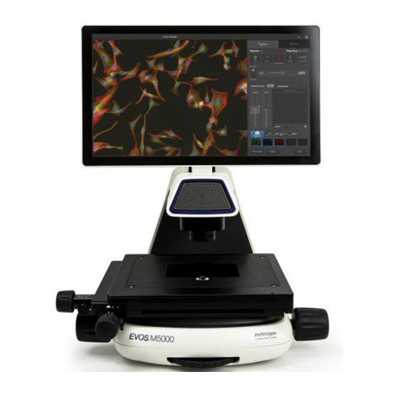
1. Product information Product description EVOS M5000 The Invitrogen EVOS M5000 Imaging System (Cat. No. AMF5000) is a fully ™ ™ ™ integrated, digital, inverted imaging system for four-color fluorescence and Imaging System transmitted-light applications. It combines precision optics, a five-objective turret, an 18.5 inch high-resolution LCD display (1920 ×... -
Page 8: Standard Items Included
Standard items included EVOS M5000 • EVOS ™ M5000 Imaging System, includes the following components and pre- ™ installed accessories: Imaging System 18.5 in articulated LCD monitor (1920 ×1080 pixel resolution) Embedded PC (4 GB RAM) Light cube shipping restraint (remove before use) Stage lock pin (remove before use) EVOS ™... -
Page 9: Instrument Exterior Components And Mechanical Controls
Instrument exterior components and mechanical controls Front view LCD monitor Focusing knobs Condenser slider slot Objective selection wheel Condenser head Vessel holder Mechanical X-Y stage Objective Stage X-axis positioning knob Phase annuli selector Stage Y-axis positioning knob Stage positioning Mechanical X-Y stage knobs and brakes Stage X-axis positioning knob Stage brake for X-axis... - Page 10 Rear view LCD monitor Network port Mechanical X-Y stage USB-A 2.0 ports (4×) Focusing knobs USB 3.0 port (1×) Power switch Stage X-axis positioning knob 4-pin power input port (12 VDC, 5 A) Stage Y-axis positioning knob* Display port (video output) * Not visible in this perspective.
-
Page 11: Graphical User Interface (Gui)
Graphical user interface (GUI) GUI layout The GUI of the system consists of the Viewing area on the left and Capture and Review tabs and the Settings and Virtual keyboard buttons on the right. Each tab and button opens the controls necessary to execute the selected function. Sign In/User: Allows you to sign in to your Connect account, Thermo Fisher’s cloud- ™... -
Page 12: Installation
2. Installation Operating environment and site requirements • The dimensions of the EVOS ™ M5000 Imaging System are 18 × 23 × 18 in (W×H×D) (46 × 59 × 46 cm). The system requires a benchtop of approximately 36 × 36 in (92 ×92 cm). •... -
Page 13: Prepare For Installation
Prepare for installation Receive and inspect Verify that the items shown on the shipping list are the same items that you ordered at the time of purchase. the shipment Carefully inspect the shipping containers and report any damage to the Thermo Fisher Scientific service representative. - Page 14 Remove shipping The EVOS ™ M5000 Imaging System is equipped with two shipping restraints (stage lock pin and light cube shipping restraint) to protect the instrument from restraints shock and vibration during transport. You must remove the shipping restraints before you power on the EVOS M5000 Imaging System.
- Page 15 Blank light cube Thread hold Screws Using the light cube tool, loosen the two screws that secure the blank light cube to the instrument. You do not need to remove the screws. Screw the light cube tool to the thread hold on the light cube, then lift the blank light cube up and out of the light cube turret.
- Page 16 Secure the UV light shield mount to the top of the condenser light shield using the two screws supplied with the UV shield assembly (not the protruding screws on the mount). Clip the condenser light shield with the attached UV light shield mount back onto the condenser head.
-
Page 17: Turn On The Evos ™ M5000 Imaging System
Turn on the EVOS M5000 Imaging System ™ Turn the instrument power switch (located on the back; see page 8) to the ON position. When the Capture tab is displayed, the EVOS ™ M5000 Imaging System is ready to use. IMPORTANT! All shipping restraints must be removed before turning on the EVOS ™... - Page 18 Sign in to your Connecting to your Connect ™ account, Thermo Fisher’s cloud-based platform, allows you to save captured images in your unique user account in addition to Connect account ™ local storage. Note: You must have a Connect ™ account or create one to sign in.
-
Page 19: Capture Images
3. Capture images Overview Capture tab The basic functions of the EVOS ™ M5000 Imaging System, such as viewing the sample, setting optimal focus, and capturing and saving images are performed in the Capture tab, which is the first screen after start-up. Workflow Select objective and light source ... -
Page 20: Capture Images In A Single Channel
Capture images in a single channel Select objective and Place the vessel containing your sample on the stage using the appropriate vessel holder. light source Note: When capturing images in fluorescence channels, place the light shield box on the stage, over the sample. This is important for optimal image quality. Set the magnification using the objective selection wheel (page 7). - Page 21 Adjust brightness For Brightness mode, select Simple or Actual. Simple mode allows you to control Brightness as a single parameter. Actual mode allows you to adjust Light (i.e., LED intensity), Exposure, and Gain parameters individually. Adjust brightness using the Brightness controls: •...
- Page 22 Focus on the Use the Coarse and Fine focus sliders to focus on the sample. sample Alternatively, click Coarse and Fine autofocus to autofocus on the sample. To limit the autofocus algorithm to a specific region along the Z-axis, use the Autofocus Maximum and Autofocus Minimum controls (blue triangles on the Coarse focus slider) to set the upper and lower bounds.
- Page 23 Optional : Configure Hover the pointer over the Viewing area to reveal the buttons for Display Settings and Analysis Tools. display settings Click Image Display Settings button to expand the controls for image display settings for the selected channel. Adjust Brightness , Contrast , and Gamma using the corresponding...
- Page 24 Capture image in a Ensure that the Channel you want to capture is selected. single channel When you select a Channel, the corresponding Capture channel box is automatically checked. Note: If you exit the Live mode, the current channel remains selected, as indicated by the blue line underneath the channel button.
- Page 25 To capture the same field of view in another channel, select the desired Channel. If needed, re-adjust the brightness and focus, then click Capture. The viewing area shows the image captured in the new channel superimposed on the image captured in the previous channel. A thumbnail of the image captured in the new channel is displayed along with the thumbnail of the image from the previously captured channel.
-
Page 26: Capture Images In Multiple Channels
Capture images in multiple channels Capture multiple To capture multiple channels simultaneously, select the desired channels by checking corresponding boxes. channels simultaneously If needed, adjust brightness and focus for each of the selected channels as described. Click Capture to acquire an image in each of the selected channels. The Viewing area shows a multicolor overlay of the images captured in each selected channel. -
Page 27: Analyze And Annotate Captured Images
4. Analyze and annotate captured images Display settings and analysis tools Display settings and analysis tools allow you to change image display settings for live and captured images in the Viewing area, annotate captured images, and perform cell count and confluence measurements. Hover the pointer over the Viewing area to reveal the buttons for Display Settings and Analysis Tools. - Page 28 Display grid Click the Grid button to superimpose a grid over the Viewing area. To change the grid size, click the Grid Settings button (arrow on the Grid split button) to open the Grid Settings tool. Select the Size for the grid. Available grid sizes depend on the magnification of the selected objective.
- Page 29 To move the scale bar, hover your pointer over the scale bar until a bounding box appears, then click within the box and drag the scale bar to the desired location within the Viewing area. To adjust the length of the scale bar, hover your pointer over the scale bar until a bounding box appears, then the click left or right side of the box and drag the box to the desired length.
-
Page 30: Add And Show Measurements And Annotations
Add and show measurements and annotations Click the Measurement and Annotations Tools button (the arrow on the Show Measurements and Annotations split button) to open the measurement and annotations tools. Using the Draw tools, draw a rectangle, line, ellipse, polygon, or a free-form shape over the region of interest on the Viewing area. -
Page 31: Show Cell Count
Show cell count Cell count tool Hover the pointer over the Viewing area to reveal Display Settings and Analysis Tools, then click the Analysis button to display Auto Count, Manual Count, and Confluence options in the tabs area. • Auto Count: Automatically counts the objects displayed in the Viewing area based on your specifications (page 30). - Page 32 Perform Auto Click the Analysis button, then select Auto Count. Count If counting from the Capture tab, select the Channel in which to count objects. This option is available only when you are counting from the Capture tab. Available options depend on the LED light cubes installed, and you can only select channels that contain captured images.
- Page 33 If needed, click Target again to identify further objects to include in your count (for example, targets that might appear different). Note: For best results, follow these guidelines when identifying target objects: • When selecting objects, circle the entire object and include a slight border around it.
- Page 34 When you are finished defining the target and background areas, the software automatically counts the objects based on your criteria. Viewing area identifies the objects that were counted with colored circles and the Object Count field displays the number of objects included in the count. To change the color of the circles that identify the objects included in the count, select the desired color from the Count Color dropdown.
- Page 35 The Refine section displays a histogram plot showing Count versus Intensity, Area, or Circularity. In this example, Area is selected. 10. To refine your count, select Intensity, Area, or Circularity, move the gate handles to set the upper or the lower boundary for the selected parameter. You can refine the count by a single parameter or by multiple parameters.
- Page 36 Perform Manual Click the Analysis button, then select Manual Count. Count Select the Channels to display in the Viewing area for manual count. You can select multiple channels, provided that they contain captured images. In this example, DAPI and TX Red channels contain captured images, and both are selected for the manual count.
- Page 37 Click on the Label number to select a label, then left-click at each point on the Viewing area to tag the items in that label category. You can switch labels as desired. As you tag the objects onscreen with the selected label, the system keeps a running tally of the counts with percentages for each label assigned.
-
Page 38: Measure Confluence
Measure confluence Confluence tool Confluence is a measure of how tightly cells are packed in a culture. When all available growth area is utilized in a culture vessel and the cells make close contact with one another, the culture is at 100% confluence. Guidelines for •... - Page 39 Click Target, then click and drag on the image to draw a circle around an area that contains cells (green circle). Click Background, then click and drag on the image to draw a circle around a background area that does not contain any cells (red circle).
-
Page 40: Save Analysis Results
Save analysis results Save When finished with the Auto count, Manual count, or Confluence measurement, click Save to open the Save Composite Image dialog, then navigate to the destination folder to save your count results. Enter File name and select File type. Select Save screenshot to preserve a detailed account of your count results as an image. -
Page 41: Save Captured Images
5. Save captured images Save Save images After capturing an image in a single channel or a set of images in multiple channels, click Save to open the Save dialog, then navigate to the destination manually folder to save your captured images. Enter a new file name for your saved images or use the default file name, then select the file format from the Save as type dropdown. - Page 42 Select Save screenshot to save an image of the entire instrument screen in addition to the captured image. Leave the Save screenshot option unselected to save only the captured image. Note: Save screenshot function allows you retain an image of the annotations and image display selections as seen in the viewing area along with the instrument controls.
-
Page 43: Quick Save Images
Quick Save images Optional : Enable Quick Save function allows you to set the save options in advance and save your captured images with a single click directly from the Capture tab or automatically Quick Save without having to click Save after each capture. Click the Quick Save Settings button (the arrow on the Save split button) to open the Quick Save Settings dialog. -
Page 44: Capture Time Lapse Images
6. Capture time lapse images Time Lapse tool With the Time Lapse tool, you can set up your cells and program the EVOS ™ M5000 Imaging System to capture images (including Z-Stack images) at given intervals over a time period based on your specifications. For repeat experiments, time lapse routines can be saved, recalled, and edited. - Page 45 Select Z-Stack to capture multiple images along the Z-axis based on your specifications. Unselect Z-Stack to capture images only at the focus position set for each channel (either Auto Focus as part of the routine or initial focus positions). If you have the optional EVOS ™...
- Page 46 Select to autofocus at Every interval or at First interval of each run, then click Next. Note: In a time lapse routine, images are captured at the end of each interval of a run. For more information, see “Intervals”, page 46. If you have opted to capture Z-Stack images, define the Top, In Focus, and Bottom positions for the Z-Stack image set.
- Page 47 10. Define the Z-Stack parameters to determine the number of “optical sections” captured in the Z-Stack image set: • Automatically compute Z-Stack Parameters: Select to calculate the number of images and their Z-positions automatically based on the Z-Stack boundaries and the default Step Size. •...
- Page 48 13. Enter the Total Time for Run 1 in Hours, Minutes, and Seconds. You can create multiple Runs for a Time Lapse Routine, each with its own duration and image capture frequency. 14. Set the Image capture options for Run 1. Available options are Frequency, Intervals, and As fast as possible.
- Page 49 15. If you have opted to use the EVOS ™ Onstage Incubator in your time lapse routine, set the Incubator options for Run 1. Enter the target values for Temperature, CO , and Oxygen. b. If desired, select Humidity to use a humidified atmosphere in the incubator.
- Page 50 17. When finished with adding Runs, click Next to set the Save options. 18. Click the Browse button, navigate to the desired destination folder for the Time Lapse images, then click Select Folder. 19. Select the File Type: PNG or TIFF. 20.
- Page 51 23. Click Start to run the Time Lapse routine. The system provides information about the progress of the Time Lapse routine as it captures the images based on the routine specifications. 24. When the Time Lapse routine is completed, the Review tab opens to the files captured in the routine.
- Page 52 Run a saved time Each time you run a Time Lapse routine, the system saves the specifics of the routine, which you can then recall and run with a new sample. lapse routine On the Capture tab, click Automate, then select Time Lapse to open the Time Lapse tool.
- Page 53 Review images and To review the results from your completed time lapse routine, click Results. The viewing area displays the first image captured in the video captured in a time lapse routine and the Review tab shows the Image Properties, time lapse routine and Time Lapse and Auto Focus Settings.
- Page 54 To play the time lapse movie, select the Time-lapse Video file, then click Play on the Time Lapse Video Player. To change the playback speed, select the desired speed from the Playback Speed menu. EVOS M5000 Imaging System User Guide ™...
- Page 55 To review individual images captured during the time lapse routine, select the desired image from the Review tab. The viewing area displays the selected image and the Review tab shows the Image Properties, and Time Lapse and Auto Focus Settings. To zoom in on the image, use the Zoom slider.
-
Page 56: Capture Z-Stack
7. Capture Z-Stack Z-Stack tool Z-Stack tool allows you to capture multiple images of a selected field at different focal planes along the Z-axis and combine them to generate a final image with a greater depth of field than any of the individual source images. Capture Z-stack images On the Capture tab, click Automate, then select Z Stack to open the Z-Stack tool. - Page 57 If not already on, click the Light button to illuminate the sample, then adjust brightness and focus using the corresponding sliders on the Capture tab. The focus position you set in this step is the initial Current Z position. To accept the Current Z as the In Focus position, click Set for In Focus. To change the In Focus position, move the Coarse and Fine focus sliders on the Capture tab to focus on the sample, then click Set.
- Page 58 Click the Browse button to open Choose Save Folder dialog. Go to the destination folder for the Z Stack images, then click Select Folder. 10. Select the File Type: PNG or TIFF. 11. Select Generate Projection Image to generate a projection image. When selected, the system uses the most in-focus pixels from images captured at different focal planes to generate a composite in-focus image.
- Page 59 13. When the Z-Stack routine is completed, the Review tab opens to the files captured in the routine. EVOS M5000 Imaging System User Guide ™...
-
Page 60: Review Saved Images
8. Review saved images The Review tab allows you to review still images, including those captured in Time Lapse routines and Z-Stacks. You can also use this tool to annotate the saved images, and to re-save or delete saved files. For the descriptions of the controls available in the Review tab, see page 86. - Page 61 To display the folder/image preview in grid format, click the Grid view button. If needed, use the scroll bar to search the preview list for the desired image file. Click the image to select it. The selected image is indicated with a box around it and the viewing area displays the selected image.
-
Page 62: Analyze Saved Images
Analyze saved images Analyze and Hover the pointer over the Viewing area to reveal the buttons for Display Settings and Analysis Tools. annotate saved images The analysis and annotations tools function in the same way in the Capture and Review tabs: •... -
Page 63: Adjust Instrument Settings
9. Adjust instrument settings Overview Settings tab The Settings tab allows you to assign objectives to the objective turret, to calibrate objective magnification, to set image and general instrument options, add and remove light cubes, and to connect to a Wi-Fi network and to map network drives. •... -
Page 64: Adjust Objective Settings
Adjust objective settings Assign objectives After adding a new objective to the objective turret or replacing an older objective, assign the new objective to the appropriate turret position. For instructions on how to remove an objective, see “Change the objectives”, page 75. Go to the Settings ... - Page 65 Calibrate objective Go to the Settings Objective Selection and Calibration, click the Action button next to the newly installed objective, then select Calibrate to launch magnification the Objective Calibration tool. Mount the EVOS ™ Calibration Slide in the vessel holder, select the objective you want to calibrate, then click Calibrate Objective.
-
Page 66: Calibrate White Balance
Calibrate white balance Calibrate white Calibrate White Balance calibrates color channel lighting. balance Go to the Settings Visuals tab, then click White Balance Calibration to open the White Balance Calibration tool. Select a 20X or higher objective, then set the phase ring to Brightfield using the Phase annuli selector (page 7). -
Page 67: Set Saturated Pixel Options
Set saturated pixel options Highlight saturated Highlight saturated pixels function displays overexposed pixels on an image with the user-defined color, which provides a visual aid for optimal illumination when pixels adjusting the brightness settings. Go to the Settings Visuals tab, then click the Highlight Saturated Pixels checkbox. -
Page 68: General Settings
General settings General settings options Define saving To save TIFF files in a Microsoft compatible format, select the corresponding option. options for TIFF files To save TIFF files uncompressed, select the corresponding option. When finished with your selections, click Done. Reverse focus Select Reverse focus wheel action. -
Page 69: Configure Network Settings
Configure network settings You can connect the EVOS M5000 Imaging System to a network via an Ethernet ™ cable or Wi-Fi adaptor and save captured images directly to shared folders on the network. You can also connect to your Connect ™... - Page 70 Map network drive Go to the Settings Network tab, then click Map Network Drive. Map Network Drive dialog opens. Select the drive you want to map from the Drive menu. Click Browse to open the Browse for Folder dialog. Navigate to the folder you want to map, then OK.
- Page 71 If you want to reconnect as a different user, check Connect using different credentials. To connect to a Web site that you can use to store your documents and pictures, click the hyperlink, then navigate to the desired Web site. After you have mapped the desired network drive and folder or connected to the website, click Finish.
-
Page 72: Service
Service Service tab displays the current software and firmware versions of the system and allows you to copy error logs, set date and time, and update software and firmware from the cloud or the USB flash drive. To view the Service tab, click the Settings button, then select Service. Copy error logs On the Service tab, click Copy Error Logs. - Page 73 Update from Cloud Restart your EVOS ™ M5000 instrument before an update to optimize the update process. To update the instrument software and firmware from the Cloud, sign in to your Connect account (page 16). ™ On the Service tab, click Update from Cloud. The instrument automatically searches your Connect ™...
-
Page 74: Instrument Care And Maintenance
10. Instrument care and maintenance General care • When cleaning optical elements, use only optical-grade materials to avoid scratching soft lens coatings. • Use the appropriate cleaning solutions for each component, as indicated in the Decontamination Procedures below. • If liquid spills on the instrument, turn off the power immediately and wipe dry. -
Page 75: Stage Care
Stage care • Clean the X-Y stage as needed with paper towels or Kimwipes ™ tissues dampened with 70% ethanol. • When moving the EVOS ™ M5000 Imaging System, be sure to lock the X-Y stage using the Shipping Restraint as shown on page 75 to prevent the stage from sliding. -
Page 76: Change Evos ™ Led Light Cubes
Change EVOS LED light cubes ™ To customize your EVOS M5000 Imaging System, you can add and remove LED ™ light cubes to fit the instrument’s functionality to your own specific research needs. Each LED light cube is coded to allow the EVOS ™... -
Page 77: Change The Objectives
Change the objectives To customize your EVOS M5000 Imaging System, you can add and remove ™ objectives to fit the instrument’s functionality to your own specific research needs. Procedure for Remove the objective you want to objective change replace from the objective turret. You may need to move the stage so that the objectives are accessible. -
Page 78: Calibrate The Objectives
Calibrate the objectives Calibrate objective magnification allows the calibration of the field of view, parfocality, and parcentration parameters of the selected objective. When calibrated, parfocality ensures that the sample stays in focus when the objective is changed, and parcentration ensures that an object in the center of the field of view stay in the center of the field no matter which objective is being used. - Page 79 Find a calibration circle that fits entirely in the field of view. Focus on the calibration circle using the focus controls. Click and drag the green calibration lines to align them along the outer borders of the calibration circle. When finished, click Save to complete the calibration. Repeat the calibration process for each additional objective to be calibrated.
-
Page 80: Appendix A: Troubleshooting
Appendix A: Troubleshooting Note: For additional technical support, contact your local EVOS ™ distributor. If you do not have your distributor information, visit thermofisher.com/evos or contact Technical Support (page 116). Image quality issues Problem Possible solutions Image is too dim (at higher Remove condenser slider, if one is in place. -
Page 81: Software Interface Issues
Software interface issues Note: We recommend keeping the EVOS ™ M5000 Imaging System up to date with the latest software. Problem Possible solutions Image does not respond to changes in Click the Light button to return to live observation. focus or stage position The controls available on the EVOS ™... -
Page 82: Appendix B: Graphical User Interface (Gui)
Appendix B: Graphical user interface (GUI) Capture tab Sign In/User: Allows you to sign in to and sign out of your Thermo Fisher Connect account. ™ Viewing area: Displays the sample. Zoom slider: Zooms in and out of the Viewing area. The zoom range is 100% to 1000%. - Page 83 Brightness mode: Toggles between Simple and Actual modes for brightness controls. • Simple mode allows you to control light intensity as a single Light parameter. • Actual mode allows you to adjust Brightness (i.e., LED intensity), Exposure, and Gain parameters individually.
- Page 84 Display settings and analysis tools: Allow you to change image display settings in the Viewing area, and analyze and annotate captured images. Image Display Settings: Opens the Image display settings tool, which allows you to adjust image display parameters (Brightness , Constrast , Gamma Correction ) for the selected...
- Page 85 Show Cell Count: Allows you to perform cell counts using the Auto Count or Manual Count tools. • Auto Count: Allows you define auto count parameters by selecting representative target objects, then count the objects by intensity, area, and circularity (page 30). •...
- Page 86 Automate: Allows you to display the controls for the Time Lapse and Z-Stack tools, and the EVOS Onstage Incubator. ™ Time Lapse: Opens the Time Lapse tool, which allows you to create and run time lapse routines to capture images at given intervals over a time period based on your specifications.
- Page 87 Incubator: Opens the Incubator Controls, which allow you to control the EVOS Onstage Incubator and monitor its status ™ during your experiments. Save: Opens the Save dialog, which allows you to select a save location, set save options, and enable the Quick Save option. EVOS M5000 Imaging System User Guide ™...
-
Page 88: Review Tab
Review tab Viewing area: Displays the sample. Folder: Displays the location of the current folder or image. Up: Goes up one folder from the current folder. Refresh: Refreshes the list or grid of images in the current folder. Grid view and List view buttons: Display the folders or saved images in grid or list view. Folder/Image display size: Increase and decrease the display size of the folders or image files. -
Page 89: Settings
Settings Objective Selection and Calibration: Allows you to assign and unassign objectives on the objective turret, and to calibrate objective magnification. Visuals: Allows you to calibrate color channel lighting (White Balance Calibration) and to assign saturated pixel colors in the Fluorescence, Transmitted, and RGB Transmitted channels. - Page 90 General: Allows you to define saving options for TIFF files and Saved Settings, and to reverse the focus wheel action. Filter Cubes: Allows you to add or remove EVOS ™ light cubes from the instrument and to assign pseudocolors to specific channels. Network: Allows you to connect to a Wi-Fi network and to map network drives.
-
Page 91: Appendix C: System Overview
Appendix C: System overview Technical specifications Note: Technical specifications of the EVOS M5000 Imaging System are subject to change without notice. ™ For the latest product information, see the product page (thermofisher.com/evos). Physical Dimensions (W × H × D): 46 × 59 × 46 cm (18 × 23 × 18 in) characteristics Weight: 16 kg (35 lbs.) Footprint: Approximately 92 cm ×... -
Page 92: Operation Principles And Technical Overview
Operation principles and technical overview LED illumination The EVOS ™ M5000 Imaging System utilizes an adjustable intensity LED light source provided by the proprietary, user-interchangeable LED light cube (see below). Because the LED light source is as close as possible to the objective turret, the number of optical elements in the channel is minimized. -
Page 93: Appendix D: Evos ™ Onstage Incubator
Appendix D: EVOS Onstage Incubator ™ EVOS Onstage The EVOS ™ Onstage Incubator (Cat. No. AMC1000) is an optional accessory for the ™ EVOS ™ FL Auto Imaging System that enables the incubation of cells on the Incubator automatic X-Y stage, allowing the capture of images from the same sample over long periods of time and recording of time lapse movies. -
Page 94: Technical Specifications
Technical specifications Note: Specifications of the Onstage Incubator are subject to change without notice. Refer to the EVOS ™ product page at www.thermofisher.com/evos for the latest product information. Physical Stagetop Environmental Chamber Control Unit characteristics Height: 25 cm (9.7 in) 37 cm (15 in) Depth: 19 cm (7.6 in) -
Page 95: Evos ™ Onstage Incubator Components
EVOS Onstage Incubator components ™ Control unit and EVOS ™ Onstage Incubator consists of an environmental chamber and a separate control unit that supplies the power and gas (air or air-CO premix, CO , and N environmental displacement in hypoxia experiments), and controls the humidity and chamber temperature. - Page 96 Environmental The environmental chamber of the EVOS ™ Onstage Incubator consists of the incubator chamber, the vessel holder/adaptor, the heated glass lid, the light chamber shield, and the light shield cover. The environmental chamber sits on the onstage incubator master plate attached to the X-Y stage of the EVOS ™...
-
Page 97: Set Up The Evos ™ Onstage Incubator
Set up the EVOS Onstage Incubator ™ Install the Onstage Remove the X-Y stage base plate from the X-Y stage by unscrewing the four 3.0-mm screws (indicated by red arrows) on the base plate. If necessary, unscrew Incubator Master and remove the vessel holder/adaptor before removing the base plate. Plate Secure the onstage incubator master plate to the X-Y stage using the four thumb screws. - Page 98 Assemble the Place the incubator chamber on the onstage incubator master plate and secure it in place using the four 2.0-mm hex screws (indicated by red arrows). environmental chamber Attach the vessel holder/adaptor to the incubator chamber using the four thumb screws (indicated by red arrows).
- Page 99 Place the light shield with tinted plastic window on top of the heated glass lid. Use of the light shield is required for fluorescence imaging applications. If desired, place the light shield cover on the light shield for fluorescence imaging applications. The light shield cover completely blocks any ambient light from entering the environment chamber and improves image quality in fluorescence imaging applications.
- Page 100 Set up for operation Follow the procedure below to set up the EVOS ™ Onstage Incubator for operation. For the locations of the various input jacks and gas ports, refer to “Control unit rear view”, page 93. IMPORTANT! Do not position the control unit so that it is difficult to turn off the main power switch.
- Page 101 Assemble the water reservoir and add warm water (approximately 50°C) to the max fill line through the fill hole (see image below). Do not overfill the water reservoir. Place the water reservoir into the control unit with the fill holes to the front and close the lid.
-
Page 102: Use The Evos ™ Onstage Incubator
Use the EVOS Onstage Incubator ™ IMPORTANT! Before using the EVOS ™ Onstage Incubator in your experiments, make sure that: • The gas inputs have been configured (see “Configure gas inputs”, page 102). • The oxygen sensor has been calibrated (see “Calibrate oxygen sensor”, page 103). - Page 103 Note: Alternatively, go to the Settings tab, click Incubator to display the Incubator panel, then click Main Incubator Control to open the Incubator Control window. Select Enable to turn on the incubator. Select the desired Shutdown option: • Manually shutdown: The incubator will remain on until the Enable option is manually deselected and the Close button is clicked.
- Page 104 Configure gas Go to the Settings tab, then click Incubator to display the Incubator panel. inputs Click Incubator Setup to open the Incubator Setup window. Select the appropriate options for the Gas Inputs that reflects your set-up for the EVOS ™...
- Page 105 Calibrate oxygen Calibrating the oxygen sensor ensures that the atmosphere in the environmental chamber is replenished with the appropriate gasses in the correct proportion. sensor Go to the Settings tab, then click Incubator to display the Incubator panel. Click Oxygen Sensor Calibration to open the Incubator Setup window. Verify that your gas connections have been correctly configured.
-
Page 106: Appendix E: Evos ™ Image Analysis
Appendix E: EVOS Image Analysis ™ EVOS Image The EVOS ™ Image Analysis is an easy to use application for storing, ™ viewing, and analyzing images from your EVOS ™ M5000 Imaging Analysis System. After you have signed in to your Connect ™... - Page 107 Edit Image Edit Image screen contains the Adjust and Analyze tabs. Adjust tab Adjust tab allows you to zoom in to your selected image, adjust brightness and contrast values, and add line measurements and annotations. The measurement and annotation functions of the EVOS ™...
-
Page 108: Appendix F: Safety
Appendix F: Safety Safety conventions used in this document Safety alert words Three safety alert words appear in this document at points where you need to be aware of relevant hazards. Each alert word—CAUTION, WARNING, DANGER— implies a particular level of observation or action, as defined below: CAUTION! –... -
Page 109: Symbols On Instruments
Symbols on instruments Electrical symbols The following table describes the electrical symbols that may be displayed on Thermo Fisher Scientific instruments. on instruments Symbol Description Indicates the On position of the main power switch. Indicates the Off position of the main power switch. Indicates a standby switch by which the instrument is switched on to the Standby condition. - Page 110 Safety symbols The following table describes the safety symbols that may be displayed on Thermo Fisher Scientific instruments. Each symbol may appear by itself or in combination with text that explains the relevant hazard (see “Safety labels on instruments”). These safety symbols may also appear next to DANGERS, WARNINGS, and CAUTIONS that occur in the text of this and other product- support documents.
-
Page 111: Safety Labels On Instruments
Safety labels on instruments The following CAUTION, WARNING, and DANGER statements may be displayed on Thermo Fisher Scientific instruments in combination with the safety symbols described in the preceding section. Hazard English Français Symbol CAUTION! Hazardous chemicals. Read the ATTENTION! Produits chimiques dangereux. Safety Data Sheets (SDSs) before handling. -
Page 112: General Instrument Safety
General instrument safety WARNING! PHYSICAL INJURY HAZARD. Use this product only as specified in this document. Using this instrument in a manner not specified by Thermo Fisher Scientific may result in personal injury or damage to the instrument. Moving and lifting CAUTION! PHYSICAL INJURY HAZARD The instrument is to be moved and the instrument... -
Page 113: Chemical Safety
Chemical safety Chemical hazard WARNING! CHEMICAL HAZARD. Before handling any chemicals, refer to warning the Safety Data Sheet (SDS) provided by the manufacturer, and observe all relevant precautions. WARNING! CHEMICAL HAZARD. All chemicals in the instrument, including liquid in the lines, are potentially hazardous. Always determine what chemicals have been used in the instrument before changing reagents or instrument components. -
Page 114: Chemical Waste Safety
Chemical waste safety Chemical waste CAUTION! HAZARDOUS WASTE. Refer to Safety Data Sheets (SDSs) and hazard local regulations for handling and disposal. Chemical waste To minimize the hazards of chemical waste: safety guidelines • Read and understand the Safety Data Sheets (SDSs) provided by the manufacturers of the chemicals in the waste container before you store, handle, or dispose of chemical waste. -
Page 115: Electrical Safety
Electrical safety DANGER! ELECTRICAL SHOCK HAZARD. Severe electrical shock can result from operating the EVOS ™ M5000 Imaging System without its instrument panels in place. Do not remove instrument panels. High‐voltage contacts are exposed when instrument panels are removed from the instrument. Fuses WARNING! FIRE HAZARD. -
Page 116: Physical Hazard Safety
Physical hazard safety Moving parts WARNING! PHYSICAL INJURY HAZARD. Moving parts can crush and cut. Keep hands clear of moving parts while operating the instrument. Disconnect power before servicing the instrument. Biological hazard safety WARNING! BIOHAZARD. Biological samples such as tissues, body fluids, and blood of humans and other animals have the potential to transmit infectious diseases. -
Page 117: Safety And Electromagnetic Compatibility (Emc) Standards
Safety and electromagnetic compatibility (EMC) standards This section provides information on: • U.S. and Canadian safety standards • European safety and EMC standards • Australian EMC standards U.S. and Canadian The CSA C/US Mark signifies that the product meets applicable U.S. and Canadian standards, including those from CSA, CSA America, ANSI, ASME, safety standards ASSE, ASTM, NSF and UL. -
Page 118: Documentation And Support
Documentation and support Related The publication numbers in this section are for the latest product versions available at the time of publication. For documentation supporting newer product documentation versions, go to thermofisher.com/support. Document Pub. No. EVOS M5000 Imaging System Quick Reference Guide MAN0017565 ™... - Page 119 thermofisher.com/support | thermofisher.com/askaquestion thermofisher.com 14 January 2020...
Need help?
Do you have a question about the invitrogen EVOS M5000 and is the answer not in the manual?
Questions and answers