Thermo Scientific Invitrogen EVOS M5000 Installation Manual
Hide thumbs
Also See for Invitrogen EVOS M5000:
- User manual (89 pages) ,
- Quick reference instructions (12 pages) ,
- Manual (119 pages)
Table of Contents
Advertisement
Quick Links
EVOS
M5000 Imaging System
™
Catalog Number AMF5000SV
Pub. No. MAN0017783 Rev. C.0
Note: For safety and biohazard guidelines, see the "Safety" appendix in the following product documentation: EVOS
System User Guide (Pub. no. MAN0017563). Read the Safety Data Sheets (SDSs) and follow the handling instructions. Wear appropriate
protective eyewear, clothing, and gloves.
Standard items included
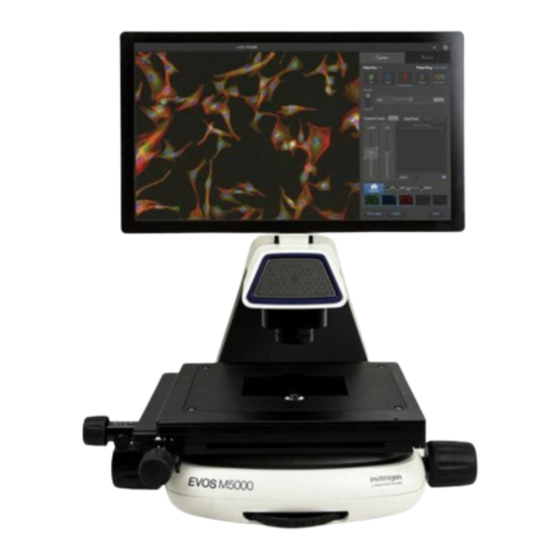
EVOS
M5000 Imaging System
™
™
EVOS
M5000 Imaging System, includes the following components and pre-installed accessories:
• 18.5 in articulated LCD monitor (1920 ×1080 pixel resolution)
• Embedded PC (4 GB RAM)
• Manual X-Y stage with position-sensing technology
• 5‑position objective turret
• Condenser with 4‑position turret
• Light cube shipping restraint (remove before use)
• Stage lock pin (remove before use)
™
• EVOS
Condenser Light Shield
• Light cube tool (remove before use)
• Blank light cube (remove before use)
• LED light cubes, as ordered
• Objectives, as ordered
EVOS
M5000 Accessories Kit
™
™
EVOS
M5000 Accessories Kit (located in the instrument box), contains:
• Wireless mouse and keyboard
• USB receiver (for wireless mouse and keyboard connection)
• USB Wi-Fi adaptor (for wireless network connection to Connect applications and mapped network drives)
• USB 3.0 flash drive, 16 GB (for image storage, preloaded with user documentation)
™
• EVOS
Vessel Holder, Multiwell Plate (Cat. No. AMEPHV022)
™
• EVOS
Vessel Holder, Two 25 × 75 mm slides (Cat. No. AMEPVH001)
™
• EVOS
Vessel Holder, Universal (Cat. No. AMEPVH009)
™
• EVOS
Calibration Slide (Cat. No. AMEP4720)
™
• EVOS
Light Shield
• UV shield assembly
• Condenser Slider, Block (Cat. No. AMEP4688)
• Condenser Slider, 4X Pupil (Cat. No. AMEP4738)
• Condenser Slider, Diffusion for Brightfield Applications (Cat. No. AMEPDFS1)
• Universal power supply (12 V, 5 A) and power cord (type B, North America)
™
• EVOS
Dust Cover
• Accessories box with adjustable compartments
For Research Use Only. Not for use in diagnostic procedures.
INSTALLATION GUIDE
™
M5000 Imaging
Advertisement
Table of Contents

Related Manuals for Thermo Scientific Invitrogen EVOS M5000


Summary of Contents for Thermo Scientific Invitrogen EVOS M5000
- Page 1 INSTALLATION GUIDE EVOS M5000 Imaging System ™ Catalog Number AMF5000SV Pub. No. MAN0017783 Rev. C.0 ™ Note: For safety and biohazard guidelines, see the “Safety” appendix in the following product documentation: EVOS M5000 Imaging System User Guide (Pub. no. MAN0017563). Read the Safety Data Sheets (SDSs) and follow the handling instructions. Wear appropriate protective eyewear, clothing, and gloves.
-
Page 2: Operating Environment And Site Requirements
• Hex key, 2 mm • Mouse pad EVOS M5000 Imaging System user documentation ™ ™ • EVOS M5000 Imaging System Quick Start Guide, printed (Pub. No. MAN0017765) ™ • EVOS M5000 Imaging System Installation Guide, printed (Pub. No. MAN0017783) • USB 3.0 flash drive (located in the accessories box) contains: ™... -
Page 3: Instrument Exterior Components And Mechanical Controls
Instrument exterior components and mechanical controls Front view LCD monitor Objective selection wheel Condenser Focusing knobs Condenser light shield USB-A 3.0 port Vessel holder and thumb screws Objective Mechanical X-Y stage Phase ring selector Stage X- and Y-axis positioning knobs ™... -
Page 4: Prepare For Installation
Rear view LCD monitor DisplayPort (video output) Mechanical X-Y stage Network port Focusing knobs USB-A 2.0 ports (2×) USB-A 3.0 port (2×) Stage X- and Y-axis positioning knobs Power switch Instrument passwords sticker Single-pin power input port (12 VDC, 5 A) Prepare for installation Receive and inspect the shipment 1. -
Page 5: Install The Instrument
Install the instrument Unpack the instrument 1. Open the shipping box and remove the accessory box. 2. Carefully lift the instrument out of the box by grasping it firmly with both hands under the support arm. IMPORTANT! ™ Do not subject the EVOS M5000 Imaging System to sudden impact or excessive vibration. - Page 6 Figure 1 Before stage reposition Figure 2 After stage reposition 3. Unscrew and remove the light cube tool, which secures the shipping restraint block to the blank light cube. 4. Remove the shipping restraint block and store it in the accessories box. Removal of the restraint block provides access to the blank light cube in the light cube turret.
- Page 7 Install the UV light shield ™ 1. Verify that the EVOS Condenser Light Shield is installed on the condenser assembly. The condenser shield is pre-installed and helps reduce the potential effects of overhead lighting on your image. 2. Pull the condenser light shield out from the condenser head. 3.
-
Page 8: Connect The Instrument
5. Peel the protective paper from the UV light shield, then slide the orange UV light shield over the two protruding screws on light shield mount to attach it to the instrument. Note: The UV light shield is provided as a safety feature and should be installed whenever the unit is in operation. The UV light shield is removable for access to the condenser sliders used in transmitted light mode. - Page 9 Power on the EVOS M5000 Imaging System ™ 1. Turn the instrument power switch (located on the back; see “Rear view” on page 4) to the ON position. ™ 2. When the Capture tab is displayed, the EVOS M5000 Imaging System is ready to use. ™...
Need help?
Do you have a question about the Invitrogen EVOS M5000 and is the answer not in the manual?
Questions and answers