
Related Manuals for ECHO Robotics RP-1200

Summary of Contents for ECHO Robotics RP-1200
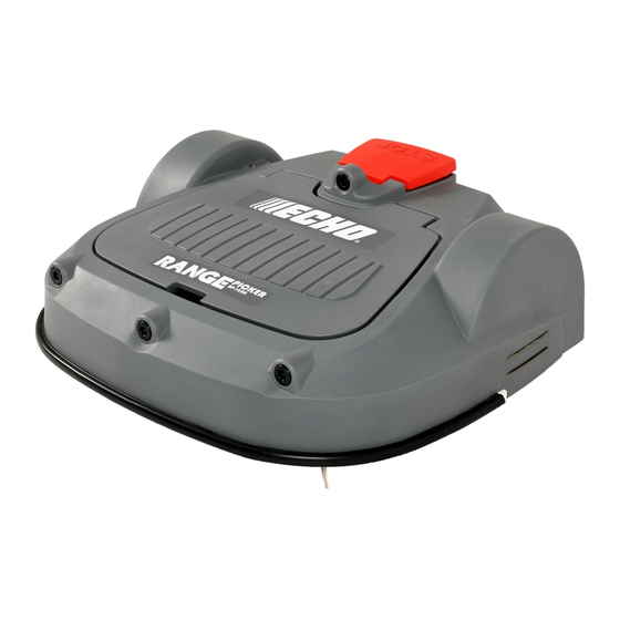
- Page 1 Technical Manual Range Picker RP-1200 P/N 99922205439 VERSION 1.0 08/06/2019 ENGLISH ©2019 ECHO Incorporated. All Rights Reserved.
-
Page 2: Table Of Contents
Chapter: 1 Important Information ......1 Administrative Support ......1 Service and Parts . - Page 3 Multi-Field Peripheral Wire Installation ....18 Obstacles ........19 Islands .
- Page 4 To View the Alarm History of a Robot ....61 To View a Map of a Robot's Movement ....61 To View a Robot's Statistics .
- Page 5 Range Picker Body ......75 Electrical Box, Battery, and Housing ....76 Chassis .
-
Page 6: Important Information
“WARNING” calls attention to an act or condition which Dealer for service procedures. CAN lead to serious personal injury or death if not Genuine ECHO Robotics parts and are available only avoided. from an Authorized ECHO Robotics Dealer. Always The safety alert symbol accompanied by the word supply a model and serial number when purchasing “CAUTION”... -
Page 7: Safety Symbols
HEORY OF PERATION AFETY YMBOLS 3 Theory of Operation 2.1 Safety Symbols The robot collects golf balls in a random pattern. The Safety and Information Label robot fills its internal collection basked with balls. When the basket is full, the robot moves to a charging Caution: The robot can be dangerous if station with a ball drop pit. -
Page 8: System Components
YSTEM OMPONENTS OBOT OMPONENTS 4.1 Robot Components 3 – Peripheral wire 4 – Charging station 5 – Obstacle 6 – Station loop peripheral wire 7 – Trackborder 8 – Drop pit 4 System Components 1 – Stop button - Press to stop the robot. Smartbox - A graphical user interface used to set configuration parameters. - Page 9 YSTEM OMPONENTS OBOT OMPONENTS 4.1.1 STOP Button The LCD Screen Located on the top of the robot. Press or lift to stop the robot. 1 – Name - The name of the robot. 2 – WiFi / Mobile connection - Indicates the robot is connected as a WiFi client.
- Page 10 YSTEM OMPONENTS OBOT OMPONENTS When the bumper contacts an object, the robot will 4.1.5 Coil touch the object, stop, move backwards, and by The coil detects the intensity of the magnetic field that default, turn between 60° and 120°, then continue is generated by the peripheral wire.
-
Page 11: Charging Station Components
YSTEM OMPONENTS HARGING TATION OMPONENTS station with a drop pit. When the robot docks at the charging station it will release balls into the drop pit. 1 – Full basket detector 2 – Ball counting band 3 – Rotational speed detector 1 –... - Page 12 YSTEM OMPONENTS OW THE OBOT ORKS 4.4.2 Autonomous Mission State The robot performs programmed instructions when in the Autonomous Mission State. NOTE: Programmed instructions can be over-ridden by instructions acti- vated from the smartbox. For a single robot application, one charging station can activate the function of the drop pit, and charge the robots battery.
- Page 13 YSTEM OMPONENTS OW THE OBOT ORKS • a specific command has been issued Charge Battery Mode • the temperature is too low The robot will return to a charging station specifically to charge when: Return to Station Mode • the battery need to be charged The robot will return to a station to: •...
- Page 14 YSTEM OMPONENTS OW THE OBOT ORKS It will then follow the trackborder in this field before 7 – Trackborder turning into it to start working. 8 – Peripheral wire of field closest to charging station Go Zone Mode describes the maneuvers the robot Wait In Station Mode makes to leave the charging station and start collecting The robot will stay in the charging station once the...
- Page 15 YSTEM OMPONENTS OW THE OBOT ORKS 4.4.4 Go Zone Mode If there are no schedule constraints, the robot will choose the field based on the percentage values. Over Go Zone Mode describes the maneuvers the robot a period of time the robot ensures that it starts in each makes to leave the charging station and start working.
-
Page 16: Installation Example
NSTALLATION XAMPLE OW THE OBOT ORKS 5 Installation Example The following figure represents the components of a typical golf course installation. Area A is the high-density ball area. Area B is the working area. nance of the outfield is essential for the optimal opera- 1 –... -
Page 17: Robots, Ball-Collecting Capacity, And Working Areas
OBOTS OLLECTING APACITY ORKING REAS OWING OBOTS 6.4 Ball Collecting Capacity robot has discharged all its balls and moved away. The second robot will then dock with the charging station attached to the drop pit. Asses the number of ball-collecting robots required and the definition of the areas in which they will work. -
Page 18: Charging Station Requirements
HARGING TATION EQUIREMENTS YPE OF HARGING TATIONS • There a clear high density zone (four times higher • one station loop wire (returns robot to charging than the density elsewhere) on busy days. station) • The high density zone is 30% of the entire working area. -
Page 19: The Drop Pit Charging Station
HARGING TATION • position the charging station on a straight section of the peripheral wire 6.0 in. (150 mm) • minimum length of wire on the incoming and outgoing side is 8.2 ft. (2.5 m) • minimum distance between charging stations is 49.2 ft. -
Page 20: Location Of The Drop Pit
NSTALLATION OCATION OF THE 8.1 Location of the Drop Pit 8.2 Drop Pit Elevator The robot will dock at the drop pit charging station multiple times per day. Consider the location carefully. 8.3 Drop Pit Without Elevator Reinforce the surface leading to the drop pit to avoid excessive wear. -
Page 21: Station Loop Wire Inside Of Peripheral Wire
NSTALLATION TATION NSIDE OF ERIPHERAL (2.0 m) (4 ± 0.5 m) (2.5 m) (2.5 m) (2.5 m) (3.5 m) 1 – Station loop wire 2 – Peripheral wire 3 – Charging station 9.3 Station Loop Wire Installation With Multiple Robots The following figure shows required dimensions. -
Page 22: Peripheral Wire Installation Next To Landscaping
NSTALLATION ERIPHERAL NSTALLATION EXT TO ANDSCAPING 9.4 Peripheral Wire Installation 9.4.4 Lawn-level planting (e.g. flower bed). Next to Landscaping 3.5 in. NOTE: The dimensional values shown apply when the (90 mm) “Wire crossing distance” parameter is at the default setting of 20 in. (510 mm). 9.4.1 Rough grass that does not need to be mowed: 29.5 in. -
Page 23: Multi-Field Peripheral Wire Installation
NSTALLATION ULTI IELD ERIPHERAL NSTALLATION 1 – Field 1 1 – Field 1 2 – Field 2 2 – Field 2 3 – Start and finish side of Field 1 peripheral wire 3 – Start and finish side of Field 1 peripheral wire 4 –... -
Page 24: Obstacles
NSTALLATION BSTACLES Overlap With Station Loop Wire In Single Field Field 1 Field 2 Field 3 (> 3.0 m) 1 – Station loop wire (> 3.0 m) 2 – Overlap area All three fields are neighbors to each other. The proportion of time that the robot spends working 1 –... - Page 25 NSTALLATION BSTACLES 9.7.1 Water Obstacle CAUTION WATER AMPLIFIES THE ELECTROMAG- NETIC SIGNAL OF THE PERIPHERAL WIRE The robot is attracted towards higher signal levels. Failure to correctly avoid a water obstacle can re- sult in submersion of the robot. • Use an island or a pseudo-island to avoid a wa- ter obstacle.
-
Page 26: Islands
NSTALLATION SLANDS 9.7.2 Obstacles Near the Boundary to be Mowed If an obstacle is less than 3.3 ft. (1.0 m) from the boundary, install the peripheral wire around the obstacle. If the distance between the obstacle and the boundary is greater than 3.3 ft. (1.0 m), but less than 16.4 ft. -
Page 27: Sloped Fields
NSTALLATION LOPED IELDS 9.11 Configuration Settings, Single Ball-Collecting Robot, Single Field Installation The instructions given are the minimum set of configu- ration parameters that must be set for this type of installation. 15.7 - 23.6 in. (400 - 600 mm) 1 –... -
Page 28: Configuration Settings, One Mowing Robot, One Ball-Collecting Robot, Single Field Installation
NSTALLATION ONFIGURATION ETTINGS OWING OBOT OLLECTING OBOT INGLE IELD NSTALLATION Confirm creation of the new wire, then press OK. Press once to return to the INFRASTRUC- TURE menu. Select the wire in the list and press Select Infrastructure > Stations > Create manual station Select Signal channel, then press . - Page 29 NSTALLATION ONFIGURATION ETTINGS OWING OBOT OLLECTING OBOT INGLE IELD NSTALLATION 9.12.1 Configuration Settings for the 9.12.2 Configuration Settings for the Mowing Robot Ball-Collecting Robot Press and hold 9 on the numeric keypad until the Press and hold 9 on the numeric keypad until the TECHNICIANS SETTINGS menu appears.
- Page 30 NSTALLATION ONFIGURATION ETTINGS OWING OBOT OLLECTING OBOT INGLE IELD NSTALLATION 9.12.3 Configuration Settings, Select wire CH0 and rename it to D-RANGE. Define the return direction required and check Two Ball-Collecting Robots, the Use trackborder parameter ON. Single Field Installation Return to the PARCELS screen and select the In this configuration three charging stations are parcel associated with the loop wire (CH1 in this required;...
- Page 31 NSTALLATION ONFIGURATION ETTINGS OWING OBOT OLLECTING OBOT INGLE IELD NSTALLATION Return to the INFRASTRUCTURE screen and Return to the INFRASTRUCTURE screen and select Parcels. select Stations. Select wire CH0 and rename it to D-RANGE. Select Create manual station. Set the Charge Define the return direction required and check parameter ON.
- Page 32 NSTALLATION ONFIGURATION ETTINGS OWING OBOT OLLECTING OBOT INGLE IELD NSTALLATION 5 – Station loop wire (CH5) 11 – Station loop wire (CH1) 6 – Station loop wire (CH4) 12 – Peripheral wire / Working area (W-area) 9.12.7 Configuration for Mowing Robot 1 9.12.8 Configuration for Mowing Robot 2 Press and hold 9 on the numeric keypad until the Press and hold 9 on the numeric keypad until the...
- Page 33 NSTALLATION ONFIGURATION ETTINGS OWING OBOT OLLECTING OBOT INGLE IELD NSTALLATION 9.12.9 Configuration for Ball-Collecting eter and select the parcel in the loop wire (LOOP DP). Robot 1 9.12.10 Configuration for Ball-Collecting Press and hold 9 on the numeric keypad until the TECHNICIANS SETTINGS menu appears.
- Page 34 NSTALLATION ONFIGURATION ETTINGS OWING OBOT OLLECTING OBOT INGLE IELD NSTALLATION 9.12.11 Configuration for One Return to the WIRE SETTINGS screen. Select Create new wire and set the Signal channel Ball-Collecting Robot, One Mowing Robot, number to the signal to be used for the “low and Two Working Areas density area”...
- Page 35 NSTALLATION ONFIGURATION ETTINGS OWING OBOT OLLECTING OBOT INGLE IELD NSTALLATION 9.12.13 Configuration for the (LD AREA in this example). Define the return direction required and check the Use track- Ball-Collecting Robot border parameter ON. Select Infrastructure > Peripheral wires Select Neighboring parcels. Select the HD AREA On the WIRE SETTINGS screen, select the first parcel and check the button ON.
- Page 36 NSTALLATION ONFIGURATION ETTINGS OWING OBOT OLLECTING OBOT INGLE IELD NSTALLATION 9.12.14 Two Ball-Collecting Robots, One Mowing Robot, Two Working Areas In this example, there are two ball-collecting robots that work predominately in the high ball density area near the driving range. Each robot requires a charging station. An additional station connected to the drop pit is required with a busy loop to ensure that the only one robot is using it at a time.
- Page 37 NSTALLATION ONFIGURATION ETTINGS OWING OBOT OLLECTING OBOT INGLE IELD NSTALLATION Return to the PARCELS screen and select the for the “return to station loop” wire (CH3 in this parcel associated with the high density area wire example). (CH1 in this example). Rename the parcel to indi- Return to the WIRE SETTINGS screen.
-
Page 38: Technician Settings Menu
ECHNICIAN ETTINGS ONFIGURATION ETTINGS OWING OBOT OLLECTING OBOT INGLE IELD NSTALLATION select the parcel in the loop wire (station loop Select Neighboring parcels. Select the HD AREA wire for ball-collecting robot 1). parcel and check the button ON. Return to PAIRED STATIONS screen. Create Return to the PARCELS screen and select the manual station (for the drop pit). -
Page 39: Infrastructure
ECHNICIAN ETTINGS NFRASTRUCTURE 10.1 Infrastructure Use this menu to configure wires, parcels, and stations. 10.1.1 Wires Signal channel The signal (frequency) channel for the peripheral wire. Wire CH# This corresponds to the channel set using the rotating switch in the charging station. In the case of a A list of defined wires is presented, with the corre- multi-field installation, each wire used, must be sponding channel number. - Page 40 ECHNICIAN ETTINGS Parcel properties Name The current name of the parcel. The name can be edited. Return direction Defines the default direction (clockwise or counter- clockwise) in which the robot returns to its charging station following the wire. Set the value of this parameter to ensure that the robot can return to the charging station in the most efficient manner.
- Page 41 ECHNICIAN ETTINGS • A start zone is defined for a parcel. 2 – Min. Bounce Angle 3 – Max. Bounce Angle • Multiple start zones can be defined for the same wire/parcel. Perimeter The Start Zone screen displays the following: This defines a distance the robot will travel along the trackborder to return to the charging station.
-
Page 42: Stations
ECHNICIAN ETTINGS TATIONS 1 – Distance Min. 2 – Distance Max. 3 – Trackborder Angle Min. / Angle Max. This is the angle that the robot will turn through to take it into the field to start working. Minimum and maximum values are defined and the robot will choose a random value between the defined limits. -
Page 43: Mobile Connection
ECHNICIAN ETTINGS OBILE ONNECTION Existing stations Connected to parcels If stations have already been defined a list of them is This defines to which of the defined parcels the station presented. is connected. For a multi-field installation a list of defined parcels will be presented and button next to Selecting a station enables you to view and edit the the required one must be checked ON. -
Page 44: Demonstration
ECHNICIAN ETTINGS EMONSTRATION 10.6 Service Bit Error Rate Number of errors during transmission. Very standard in The Service menu contains the following options: every communication. • Calibrations ICCID • Information Integrated circuit card identifier. • Tests • Software update IMEI International Mobile Equipment Identity. - Page 45 ECHNICIAN ETTINGS ERVICE X/Y CHARGE _LR Disable Sensors X represents the current test in the current sequence. The sides of the bumper that need to be disabled (Bumper Left Bumper Right) Y represents the total number of tests to be performed in the current sequence.
- Page 46 ECHNICIAN ETTINGS ERVICE Disable Sensors • the motor drives the wheel forward at 0.2 mph (0.1m/s) The number of sensors that need to be deactivated • a current of 2.5 A is delivered to the motor (CollisionLeft, CollisionRight). To test the Drive Motor To test the Back Sensors Check that CollisionLeft and CollisionRight are Press...
-
Page 47: Technician Settings Advanced Parameters
SING THE OBOT ECHNICIAN ETTINGS DVANCED PARAMETERS 10.7 Technician Settings roller position up and down to check that it moves between the two stops. Advanced parameters To test the Linear Actuator Press to start the test Max speed Sets the maximum speed at which the robot will move Press to continue if you don't want to (maximum speed is 2.2 mph [3.2 km/hr]). -
Page 48: Actions Menu
SING THE OBOT CTIONS • Only use the robot charging station to charge the NOTE: If the STOP button cover is not closed withing 10 robot’s battery. Use of any other charger can seconds, the operation is canceled and will need to be cause damage and loss of warranty coverage. - Page 49 SING THE OBOT ERVICE 11.3.1 Regional Parameters 11.3.2 Connections Use this option to set the robot time zone and the To display the connections screen: language. Press To set the time zone: The Connections screen will display. Use the arrow keypad to select an option. Press Press the arrow keys to highlight Regional IP address...
- Page 50 SING THE OBOT ERVICE • To modify the current network, highlight the To set the operating parameters: network, press . The following operations are Press available: Use the arrow keys to highlight Operations, then – Disable Network - Disconnects the press robot from this network.
- Page 51 SING THE OBOT ERVICE 11.3.6 Device info Identification of the Access Point Network To see the device info: MAC address Press MAC address. Press the arrow keys to highlight Device then press 11.3.7 System version To see the System version information: Highlight Device info and press •...
-
Page 52: Service Menu
SING THE OBOT ERVICE Use the numeric keypad to enter the required Press to accept the new setting. value. From now on certain commands will require the PIN code to be entered before they can be executed. Press to return to the main menu. Change pin code 11.3.10 Advanced Parameters Use to change the pin code. - Page 53 SING THE OBOT ERVICE Mode Select to set the mode in which the robot is to operate. Mode selections are: • OFF - The robot will not be connected to a network. • Client - The robot will connect to the selected network as a client.
- Page 54 SING THE OBOT ERVICE 11.4.3 Using the Robot as a Client 11.4.5 Device For normal operation, set up the robot as a WiFi client. Use this menu to display the characteristics of the This will enable the robot to communicate with the device and change the robot’s name.
- Page 55 SING THE OBOT ERVICE Serial number • Press to scroll through the list. Serial number of the robot. Version Latitude Current software version. Current latitude of the robot position. Brain version Longitude Current AI version. Current longitude of the robot position. System version Visible satellites Current version of the system software.
-
Page 56: Error Messages
RROR ESSAGES IRECT NTERACTION WITH THE OBOT this area, a security notification will be issued. The circular area is defined by its center and a radius. The current location of the center point can be viewed in the device settings menu. ADVANCED PARAMETERS Wire CH1: -11.29 Good shape Wire CH0: +511.75 Bad shape... -
Page 57: Remote Access Via The Web Server
ONNECTING TO OBOTS EMOTE CCESS IA THE ERVER There are five entities in the image below that are related in a hierarchical structure. The parent entity is the “City Authority”. It has four child entities: • Sports Field 1 • Sports Field 2 •... - Page 58 ONNECTING TO OBOTS EMOTE CCESS IA THE ERVER used to access the web server are created at the Stage 2: The parent entity creates a user account for moment when the robot is commissioned. Following the new entity manager this, the account holder will receive an email from Once the new entity has been created, a user account which the account can be activated.
- Page 59 To Activate an Account You can then: Open the “Account validation” email received • Modify your profile parameters. from ECHO Robotics. • Change your password. Copy the link in the email into the address bar of • See a list of your robots and information about a browser.
- Page 60 ONNECTING TO OBOTS EMOTE CCESS IA THE ERVER • Create and manage users and entities. This func- My Robots tionality is only available to users who have a suitable role. • Specify the type of notifications you want to receive and how they will be delivered. •...
- Page 61 ONNECTING TO OBOTS EMOTE CCESS IA THE ERVER The time period is shown in the period field. To adjust NOTE: You can add a “Symbolic” map of the field which the time period, use the up and down arrows to choose improves the visualization of the robot movements.
- Page 62 ONNECTING TO OBOTS EMOTE CCESS IA THE ERVER Manage Robots The breadcrumb above the list is adapted. Clicking on any entry will take you to that level. This enables the user to: To Create a New Entity • view the robots in an entity Select the parent of the new entity in the Entities •...
- Page 63 Choose the delivery method: • Email - to your email address • Smartphone - the notification can be viewed in the ECHO Robotics application Click . The list of users and their parent Click entity will be displayed. To Modify a Notification To View the Properties of a User Click on the user in the list.
-
Page 64: Using The Application
CCESSING THE ERVER SING THE PPLICATION • Change your password. • See a list of your robots and information about their activity, alarms, statistics and the map of the field they mow. • Create and manage users and entities. This func- tionality is only available to users who have a 13.3 Using the Application suitable role. -
Page 65: My Robots
OBOTS EARCH FOR A OBOT 15.3 View the Current Status and : There are no restrictions on the pass- NOTE word. Use a strong password which has at Issue a Command least 12 characters and includes numbers, symbols, and a mixture of upper and lower Click on the robot in the Favorites list. -
Page 66: To View The Alarm History Of A Robot
REATING CCOUNTS IEW THE LARM ISTORY OF A OBOT 15.7 To View the Alarm History Click on of a Robot To change the presentation of the data click on If the robot is in an alarm state, this will be indicated in to see cumulative data in a pie chart. -
Page 67: Creation Of An Account By An End-User
REATING CCOUNTS REATION OF AN CCOUNT BY AN USER Enter a description if necessary (this is optional). Click on the entity. Enter the “Street”, “Number”, “City”, “Postcode” The robot will be transferred and the information and “Country” fields (all are required). updated on the screen. -
Page 68: Account Activation
This enables the user to: Open the “Account validation” email received • view the robots in an entity from ECHO Robotics. • view the properties of a robot Copy the link in the email into the address bar of •... -
Page 69: Managing Robots
ANAGEMENT ANAGING OBOTS 17.5 Managing Robots NOTE: The information given here, refers to the opera- tions available from the Management section of the web-server. 17.5.1 To View the Robots in an Entity Enter the name (or part of the name) in the search field. -
Page 70: Notifications
• Smartphone - the notification can be NOTE: The properties of a user can not be modified viewed in the ECHO Robotics application here. This must be done by the user adapting his profile. 17.6.3 To Create a New User:... -
Page 71: Using The Application
SING THE PPLICATION AINTENANCE HART liability in case of accident due to the use of non-OEM parts. 21.1 Maintenance Chart 20 Using the Application Component Weekly 6 months Annual Inspect Cover You can view information about your robots using an /Clean application that can be downloaded onto a tablet or a Charge contacts... - Page 72 OBOT AINTENANCE INTER ERVICE HECK Service Tests Service Inspections (indicate condition as appropriate) (indicate condition as appropriate) Backward Sensors Inspect the inside of the cover and the chassis: Signal Sensors • cable condition Drive Motor (gear (check for cuts or motor) abrasions) Sonar Sensors...
-
Page 73: General Inspection And Cleaning
OBOT AINTENANCE ENERAL NSPECTION AND LEANING Service Inspections (indicate condition as appropriate) Inspect the backwards sensors. Inspect all electrical cables for cuts or abrasions. Verify that all connectors are securely assembled. Replace damaged cables. 21.3.1 Charge Contacts Electrical box: check cable connections, Clean once per week. -
Page 74: Service Procedures
Complete all weekly, 6 month, and annual main- tenance procedures. • Schedule service procedures with an authorized ECHO Robotics dealer (if required). • Store the robot in a protected dry location where the temperature is above 32° F (0° C). -
Page 75: Bumper Replacement
ERVICE ROCEDURES UMPER EPLACEMENT Assemble the new bumper assembly to the cover. Insert and securely seat the replacement sonars into the cover. Assemble the bumper retaining screws, tighten to 1.5 lbf• ft (2 N•m). Connect the sonar cables and replace the cover. Connect the bumper cable to the bumper. -
Page 76: Rear Lift Cushion Replacement
ERVICE ROCEDURES USHION EPLACEMENT 4 – Bottom washer 5 – Bottom screw 22.4 Rear Lift Cushion Replacement Remove the cover. Remove the rear lift cushion from the bracket. The bracket is captive to the chassis. Assemble the new rear lift cushion. Complete the Lift Sensor Service Test. -
Page 77: Battery Removal And Installation
ERVICE ROCEDURES ATTERY EMOVAL AND NSTALLATION 4 – Axle 5 – Gear motor assembly Installation: Connect the gear motor cable. Place the gear motor assembly into the axle. Seat the assembly into the holes of the axle flange. Assemble the washers and nuts to the gear motor assembly. -
Page 78: Correcting Stop Button Lid Closure Problems
ERVICE ROCEDURES ORRECTING UTTON LOSURE ROBLEMS In order for the robot to be able to execute its missions the lid needs to be shut, and to form a closed circuit between magnets on the lid and relays on the body. This circuit needs to be open when the lid is open. -
Page 79: Torque References
ORQUE EFERENCES ORRECTING UTTON LOSURE ROBLEMS to the magnets. Select Service > Tests > Lid from the service menu. 22.8.2 Magnets Assemble the magnets to the lid at the positions shown in the figure below. 1 – Relay (NO - normally open) 2 –... -
Page 80: Range Picker Body
ORQUE EFERENCES ANGE ICKER 23.1 Range Picker Body 1.5 lbf· † (2 N·m) 1.5 lbf· (2 N·m) † 6 lbf· <1 lbf· (5 N·m) † (<0.7 N·m) 1.5 lbf· 5 lbf· † (2 N·m) 1.5 lbf· 1.5 lbf· (7 N·m) (2 N·m) 1.5 lbf·... -
Page 81: Electrical Box, Battery, And Housing
ORQUE EFERENCES LECTRICAL ATTERY OUSING 23.2 Electrical Box, Battery, and Housing 4.5 lbf· (6 N·m) 4.5 lbf· (6 N·m) 9 lbf· † (12 N·m) 2 lbf· (3 N·m) 9 lbf· (12 N·m) † 2 lbf· (3 N·m) 2 lbf· (3 N·m) 1.5 lbf·... -
Page 82: Chassis
ORQUE EFERENCES HASSIS 23.3 Chassis † 9 lbf· † (12 N·m) 2 lbf· † † 2 lbf· (3 N·m) † † (3 N·m) † 2 lbf· † (3 N·m) † 9 lbf· † (12 N·m) † 4.5 lbf· † (6 N·m) 2 lbf·... -
Page 83: Rear Sensors
ORQUE EFERENCES ENSORS 23.4 Rear Sensors 0.75 - 1 lbf· 9 lbf· † (1.0 - 1.5 N·m) † (12 N·m) 1.5 lbf· † (2 N·m) 9 lbf· 1.5 lbf· † (12 N·m) (2 N·m) 1.5 lbf· (2 N·m) 9 lbf· (12 N·m) †... -
Page 84: Wheels
ORQUE EFERENCES HEELS 23.5 Wheels 9 lbf· † (12 N·m) 33 lbf· 0.75 - 1.0 lbf· 9 lbf· † (45 N·m) (1.0 - 1.5 N·m) † (12 N·m) 7.5 lbf· 7.5 lbf· (10 N·m) (10 N·m) 7.5 lbf· (10 N·m) 1.5 lbf·... -
Page 85: Wheel Gearbox
ORQUE EFERENCES HEEL EARBOX 23.6 Wheel Gearbox 4 lbf· † (3 N·m) 1 lbf· (1.5 N·m) 4.5 lbf· 2 lbf· †† (6 N·m) † (3 N·m) † Loctite 243 Blue Threadlocker †† Loctite 2701 Green Threadlocker... -
Page 86: Barrow Components
ORQUE EFERENCES ARROW OMPONENTS 23.7 Barrow Components 3 lbf· (4 N·m) † 9 lbf· 15 lbf· † (12 N·m) (20 N·m) †† 15 lbf· †† (20 N·m) Hand assembly 3 lbf· only †† 15 lbf· † (4 N·m) † (20 N·m) 1.5 lbf·... -
Page 87: Barrow Frame
ORQUE EFERENCES ARROW RAME 23.8 Barrow Frame 9 lbf· † (12 N·m) 9 lbf· † (12 N·m) 9 lbf· 9 lbf· † (12 N·m) † (12 N·m) 9 lbf· (12 N·m) † 9 lbf· † (12 N·m) 9 lbf· 9 lbf· 9 lbf·... -
Page 88: Chapter: 24 Technical Specifications
ECHNICAL PECIFICATIONS ATTERY 24 Technical 24.3 Software and Monitoring Specifications Security PIN code GPS positioning Standard APP robot management 24.1 Battery 24.4 Intelligence Type Lithium-ion Nominal Voltage 25.6 V Sonar detection of Height 15.7 in. (400 mm) Nominal Capacity 19.2 Ah obstacle Diameter 2.0 in. -
Page 89: Dimensions
ECHNICAL PECIFICATIONS IMENSIONS 24.6 Dimensions 53.0 in. (1344 mm) 37.3 in. (948 mm) 44.6 in. (1132 mm) 46.4 in. (1178 mm) 21.3 in. (542 mm) 17.5 in. (445 mm) 13.4 in. 23.7 in. (341 mm) (603 mm) - Page 90 ECHO Incorporated 400 Oakwood Road Lake Zurich, IL 60047 1-800-392-0329 www.echorobotics.com...
Need help?
Do you have a question about the RP-1200 and is the answer not in the manual?
Questions and answers