
Related Manuals for Analog Devices EV-21569-SOM


Summary of Contents for Analog Devices EV-21569-SOM
- Page 1 ® EV-21569-SOM Manual Revision 1.0, September 2020 Part Number 82-EV-21569-SOM-01 Analog Devices, Inc. One Technology Way Norwood, MA 02062-9106...
- Page 2 Analog Devices, Inc. reserves the right to change this product without prior notice. Information furnished by Ana- log Devices is believed to be accurate and reliable. However, no responsibility is assumed by Analog Devices for its use; nor for any infringement of patents or other rights of third parties which may result from its use. No license is granted by implication or otherwise under the patent rights of Analog Devices, Inc.
-
Page 3: Table Of Contents
Manual Contents ............................1–1 Technical Support ............................1–2 Supported Integrated Circuit ......................... 1–2 Supported Tools............................. 1–3 Product Information ............................1–3 Analog Devices Website..........................1–3 EngineerZone ............................. 1–3 Using the Board Product Overview ............................2–1 Package Contents............................2–3 Default Configuration ........................... 2–3 CrossCore Embedded Studio (CCES) Setup .................... - Page 4 Power ( LED5 ) ............................3–10 GPIO ( LED4, LED6, LED7 ) ......................3–10 Reset ( LED8 )............................3–11 Connectors ..............................3–11 JTAG ( P1 ).............................. 3–12 MicroUSB Connector ( P2 ) ........................3–12 SoM Interface Connection ( J1,J2,and J3 )..................3–13 ® EV-21569-SOM Manual...
-
Page 5: Preface
(CCES) software development tool chain is required for a full evaluation of this hardware platform. The EV-21569-SOM can also be used in a limited standalone mode while not plugged into a SoM Carrier such as the EV-SOMCRR-EZKIT or EV-SOMCRR-AUTO . The standalone mode is useful for evaluat- ing the CCES Software Development Tools and benchmarking software algorithms that do not require peripheral I/O. -
Page 6: Technical Support
A companion file in PDF format documenting all of the circuits used on the board is available on the website http://www.analog.com/EV-21569-SOM Technical Support You can reach Analog Devices technical support in one of the following ways: • Post your questions in the processors and DSP support community at EngineerZone ®... -
Page 7: Supported Tools
If you are a registered user, just log on. Your user name is your e-mail address. EngineerZone EngineerZone is a technical support forum from Analog Devices, Inc. It allows you direct access to ADI technical support engineers. You can search FAQs and technical information to get quick answers to your embedded process- ing and DSP design questions. -
Page 8: Using The Board
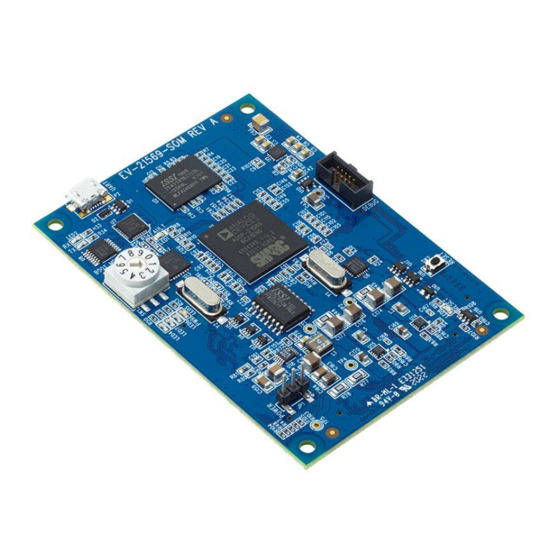
This chapter provides information on the major components and peripherals on the board, along with instructions for installing and setting up the emulation software. Product Overview Below is an image of the EV-21569-SOM board. Figure 2-1: Board View ® 2–1... - Page 9 Product Overview The board features: • Analog Devices ADSP-21569 processor • 400 ball BGA • 25 MHz oscillator • DDR3 Memory • 512Mx16 bit (8Gbit ) • ISSI IS43TR16512BL-125KBL • 1.35V • SPI Flash Quad (SPI2) Memory • 512Mbit • ISSI IS25LP512M - 512M-bit Serial Flash Memory with Dual and Quad SPI •...
-
Page 10: Package Contents
Package Contents Your EV-21569-SOM package contains the following items. • EV-21569-SOM board Contact the vendor where you purchased your EV-21569-SOM evaluation board or contact Analog Devices, Inc. if any item is missing. Default Configuration The EV-21569-SOM board is designed to run as a standalone unit. -
Page 11: Crosscore Embedded Studio (Cces) Setup
CrossCore Embedded Studio (CCES) Setup Boot Mode Select Power Selection Reset Button Figure 2-2: Default Hardware Setup CrossCore Embedded Studio (CCES) Setup Information on using the CCES tools is available at: https://analog.com/cces-quickstart 2–4 ® EV-21569-SOM Manual... -
Page 12: Debug Interface
ICE-2000 to for debugging. When the EV-21569-SOM is connected to a carrier board the Debug Agent on the carrier board can be used. To use this Debug Agent, all postions on SW1 (on the carrier board) must be in the ON position. If an emulator, such as the ICE-1000 or ICE-2000, is used instead all postions on SW1 must be in the OFF position. -
Page 13: Ft232R - Usb To Uart
• UART signal inversion option • +3.3V (using external oscillator) to +5.25V (internal oscillator) single supply operation • Low-operating and USB suspend current • Low USB bandwidth consumption • UHCI/OHCI/EHCI host controller compatible • USB 2.0 full speed compatible 2–6 ® EV-21569-SOM Manual... -
Page 14: Is25Lp512M - 512M-Bit Serial Flash Memory With Dual And Quad Spi
• Programmable CAS WRITE latency (CWL) based on tCK • Programmable Burst Length: 4 and 8 • Programmable Burst Sequence: Sequential or Interleave • BL switch on the fly • Auto Self Refresh(ASR) • Self Refresh Temperature(SRT) ® 2–7 EV-21569-SOM Manual... - Page 15 • TDQS (Termination Data Strobe) supported (x8 only) • OCD (Off-Chip Driver Impedance Adjustment) • Dynamic ODT (On-Die Termination) • Driver strength : RZQ/7, RZQ/6 (RZQ = 240 Ω) • Write Leveling • Up to 200 MHz in DLL off mode 2–8 ® EV-21569-SOM Manual...
-
Page 16: Hardware Reference
The Block Diagram figure shows the board configuration. Figure 3-1: Block Diagram The EV-21569-SOM board is designed to demonstrate the ADSP-21569 processor’s capabilities. The board has a 25 MHz input clock and runs at a max core clock frequency of 1GHz. - Page 17 The default is shown by black boxes located closer to the ON label of the switches. In order to disconnect these switches, physically move the switch to the OFF position. Figure 3-3: Example of a Mechanical Switch (Equivalent to Example of Individual FET Switches Figure) 3–2 ® EV-21569-SOM Manual...
- Page 18 In this example, the Microchip I/O expander is not shown but controls the signal CONTROL_LETTER_NUMBER and allows the user to change the selection through software. ® 3–3 EV-21569-SOM Manual...
- Page 19 SWE and SWF is OFF. In order to connect the letters instead of the numbers, the user physically changes all switches on SWC and SWD to the OFF position and all switches on SWE and SEF to the ON position. 3–4 ® EV-21569-SOM Manual...
-
Page 20: Softconfig On The Board
Programming SoftConfig Switches On the board, two Microchip MCP23017 devices exist. Each of these devices has the following programming char- acteristics: • Each GPIO register controls eight signals (software switches). GPIO Register Register Address GPIOA 0x12 ® 3–5 EV-21569-SOM Manual... - Page 21 FET column. The Component Connected column shows the board IC that is connected if the FET is enabled. The Microchip (U13) is controlling the enable signal of a FET switch. Also note that if a particular functionality of the processor signal is being used, it is in bold font in the Processor Signal column. 3–6 ® EV-21569-SOM Manual...
- Page 22 Table 3-5: Output Signals of Microchip GPIO Expander (U13 Port B) Signal Name Description Processor Signal Connected Default (if applicable) NOT USED NOT USED NOT USED NOT USED NOT USED NOT USED NOT USED NOT USED ® 3–7 EV-21569-SOM Manual...
-
Page 23: Switches
Switches Switches This section describes operation of the switches. The switch locations are shown in the Switch/Jumper Locations figure. Boot Mode Select Power Selection Reset Button Figure 3-6: Switch/Jumper Locations 3–8 ® EV-21569-SOM Manual... -
Page 24: Boot Mode Select ( Sw1 )
Power ( JP1 ) The power jumper ( JP1 ) selects the input power source to the EV-21569-SOM board. Pin 1-2 selects power input from the P2 USB port and Pin 2-3 selects Power from the SoM Interface Connectors. When using the EV- SOMCRR-EZKIT carrier board or other plug in carrier board, use Jumper setting Pin 2-3. -
Page 25: Fault ( Led1 )
When ON (green), it indicates that power is being supplied to the board properly. GPIO ( LED4, LED6, LED7 ) Three LEDs are connected to the SoftConfig (see the GPIO LEDs table). The LEDs are active high and are turned ON (amber) by writing to the U13 SoftConfig IC. 3–10 ® EV-21569-SOM Manual... -
Page 26: Reset ( Led8 )
LED. For more information, see Reset Pushbutton ( SW2 Connectors This section describes connector functionality and provides information about mating connectors. The connector locations are shown in the Connector Locations figure. Micro JTAG Figure 3-8: Connector Locations Top View ® 3–11 EV-21569-SOM Manual... -
Page 27: Jtag ( P1 )
MicroUSB Connector ( P2 ) USB Connection for FTDI RS232 to USB connection, and also power to SoM when JP1 pins 1-2 are set. Part Description Manufacturer Part Number MicroUSB 2.0 Hirose ZX62D-AB-5P8(30) Mating Cable USB A to MicroUSB 3–12 ® EV-21569-SOM Manual... -
Page 28: Som Interface Connection ( J1,J2,And J3 )
These signals are based upon the peripheral signal needs, which allows multiple DSPs to be used with this connec- tion. These connectors are self-mating and the pinout here reflects the connectors on the EV-21569-SOM. The SoM Interface A Connector (J1), SoM Interface B Connector (J2), and SoM Interface C Connector (J3) tables show the signal associated with each pin on the connectors. - Page 29 TWI2_SCL GND9 LINKPORT0_CLK SPI1_SSb UART2_TXb GND10 LINKPORT1_CLK Table 3-10: SoM Interface C Connector (J3) Signal Signal Signal Signal Signal GND1 GND7 GND2 GND4 CLK1 GPIO3 CLK2 GPIO4 GND3 GND11 GND8 GPIO5 VDD_EXT JTG0_TMS/ GPIO6 SWDIO VDD_VREF 3–14 ® EV-21569-SOM Manual...
- Page 30 JTG0_TRST GND10 SoM_Reset VDD1 SYS_CLKOUT TARGET_RESET 78 GPIO1 VSS1 GND6 VDD2 AUDIO_CLK GND9 GPIO2 VSS2 Table 3-11: Mating Connector Part Description Manufacturer Part Number 100-pin, 0.64 mm SAMTEC LSS-150-01-L-DV-A-K Mating Connector 100-pin, 0.64 mm SAMTEC LSS-150-01-L-DV-A-K ® 3–15 EV-21569-SOM Manual...
- Page 31 ® EV-21569-SOM Manual...
Need help?
Do you have a question about the EV-21569-SOM and is the answer not in the manual?
Questions and answers