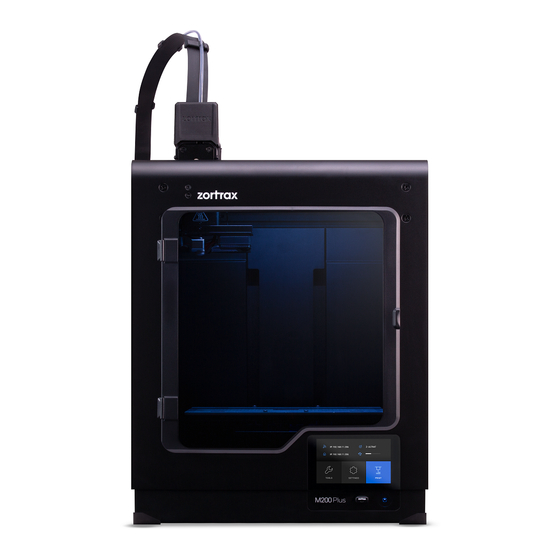
Summary of Contents for zortrax M200
- Page 1 Extruder PCB Replacement SOURCE: https://support.zortrax.com/extruder-pcb-replacement/ page 1 / 14...
-
Page 2: Table Of Contents
Table Of Content Unloading the Material Unplugging the Power Cable Material Guide Removal Unplugging the Extruder Cable Unplugging all Cables from the Extruder PCB Unscrewing the Extruder PCB Extruder PCB Assembly Plugging all Cables into the Extruder PCB Plugging the Extruder Cable Material Guide Installation Plugging the Power Cable page 2 / 14... - Page 3 If you have the extruder PCB v1, you also have to replace the hotend and heater&thermocouple. The following manual shows the M200 repair work. For the M300, these procedures are the same. page 3 / 14...
-
Page 4: Unloading The Material
Unloading the Material From the main menu select Material and then Unload the material option. The extruder will start to heat up automatically. Once it is hot, the motor will start to unload the material. page 4 / 14... -
Page 5: Unplugging The Power Cable
Unplugging the Power Cable Turn off the printer and unplug the power cable. page 5 / 14... -
Page 6: Material Guide Removal
Material Guide Removal Detach the material guide from the extruder cover. Next, separate the guide from the extruder cable. page 6 / 14... -
Page 7: Unplugging The Extruder Cable
Unplugging the Extruder Cable Detach the extruder upper printed cover and unplug the extruder cable. page 7 / 14... -
Page 8: Unplugging All Cables From The Extruder Pcb
Unplugging all Cables from the Extruder PCB Unplug all the cables from the extruder PCB. page 8 / 14... -
Page 9: Unscrewing The Extruder Pcb
Unscrewing the Extruder PCB Unscrew the two screws that secure the extruder PCB using a 2mm Allen key. Remove the PCB from the extruder. page 9 / 14... -
Page 10: Extruder Pcb Assembly
Extruder PCB Assembly Place the extruder PCB in its place and secure it with the two screws. page 10 / 14... -
Page 11: Plugging All Cables Into The Extruder Pcb
Plugging all Cables into the Extruder PCB Plug all the cables in. Remember to arrange the cables so that they don’t get damaged, e.g. by wrapping against each other. page 11 / 14... -
Page 12: Plugging The Extruder Cable
Plugging the Extruder Cable Plug the extruder cable in, and then attach the extruder upper cover to the lower cover. Make sure the extruder cable is properly plugged in. page 12 / 14... -
Page 13: Material Guide Installation
Material Guide Installation Attach the material guide to the extruder cover. Next, secure the guide to the extruder cable with the material guide clamps. Make sure the material guide is properly installed in the cover. page 13 / 14... -
Page 14: Plugging The Power Cable
Plugging the Power Cable Plug the power cable in. page 14 / 14...


Need help?
Do you have a question about the M200 and is the answer not in the manual?
Questions and answers