Table of Contents
Advertisement
Quick Links
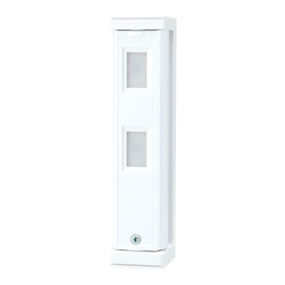
Compact outdoor
Compact outdoor
detector
detector
fit series
fit series
• Long battery life
• Easy wiring by a connector
• Multi fixing separate box
CONTENTS
1-1 BEFORE INSTALLATION ...................................... 1
1-2 PARTS IDENTIFICATION ...................................... 2
1-3 DETECTION AREA ................................................ 2
2-1 WIRING DIAGRAM ................................................ 2
2-2 TRANSMITTER PREPARATION ........................... 3
2-3 BEFORE WALL MOUNTING ................................. 3
2-4 STACKING METHOD............................................. 4
3-1 WALK TEST ........................................................... 7
4-1 WALK TEST MODE ............................................... 7
1
INTRODUCTION
1-1
BEFORE INSTALLATION
Failure to follow the instructions provided with this indication and improper handling may cause
Warning
death or serious injury.
Failure to follow the instructions provided with this indication and improper handling may cause
Caution
injury and/or property damage.
The check
mark indicates recommendation.
Warning
Do not remove the PCB.
Mounting height.
0.8 to 1.2 m
(2.6 to 3.9 ft.)
Parallel
Install the detector in a place where it is free from false alarm factors. For example:
• Sunlight and reflection
WIRELESS MODEL
• Compact design
• 190° adjustable bracket
• Intelligent AND logic
The nix
Caution
Do not remove
the separate box
tamper.
Keep the detector
parallel to the ground.
• Heat source
EN-1
INSTALLATION INSTRUCTIONS
FTN-R
Battery operated model with 2 PIRs
FTN-RAM
FTN-R with anti-masking
• Digital anti-masking (RAM model)
• Wall tamper (option)
4-2 BATTERY SAVING TIMER .................................... 7
4-3 ALARM & TROUBLE OUTPUT .............................. 8
4-4 LED ........................................................................ 8
4-5 PIR SENSITIVITY .................................................. 8
4-6 ANTI-MASKING...................................................... 8
5-1 WALL TAMPER (OPTION) CONNECTION ........... 9
5-2 LED LIGHT PATTERN ........................................... 9
6-1 HOW TO REPLACE BATTERY ............................. 9
6-2 BATTERY LIFE ...................................................... 9
7-1 SPECIFICATIONS................................................ 10
7-2 DIMENSIONS....................................................... 10
sign indicates prohibition.
Do not touch
the PCB except for
the DIP switch.
Consider the direction of the intruder,
for the setting of the detection area.
Tilt
• Objects moving in the wind
No.59-2267-1
Caution
ON
ON
1
1
2
2
3
3
4
4
5
5
6
6
Advertisement
Table of Contents

Related Manuals for Optex fit Series


Summary of Contents for Optex fit Series
-
Page 1: Table Of Contents
No.59-2267-1 INSTALLATION INSTRUCTIONS Compact outdoor Compact outdoor detector detector fit series fit series FTN-R Battery operated model with 2 PIRs WIRELESS MODEL FTN-RAM FTN-R with anti-masking • Long battery life • Compact design • Digital anti-masking (RAM model) • Easy wiring by a connector •... -
Page 2: Parts Identification
PARTS IDENTIFICATION Bracket Separate box Connector for POWER and ALARM Sponge Main unit Separate box cover Sponge for transmitter Main unit cover Connector for TROUBLE For joint Lens Screw Plate nut (M3 × 10mm) For wall mounting Screw (3 × 20 mm) Fixture Sponge Separate box tamper... -
Page 3: Transmitter Preparation
TRANSMITTER PREPARATION The transmitter used should have the internal dimensions of H 130 × W 30 × D 35 mm. (H 5.12 × W 1.18 × D 1.38 inches) Connectors to be used Unit: mm (inch) How to position a battery Connector for POWER and ALARM Black 35 (1.38) -
Page 4: Stacking Method
STACKING METHOD For the side-by-side method and the top-to-bottom method, refer to page 6. Open the knockout. Pull the connectors through the wiring knockout. Separate box Separate box cover Wall mounting Joint screw knockout knockout Wiring knockout Joint screw Wall mounting knockout knockout Attach the separate box cover and the... - Page 5 Determine the horizontal detection angle Determine the detection length. (2 m or 5 m) and attach the fixture. Note>> • To make adjustments, remove the fixture. Note>> • Check that the fixture and bracket engage correctly. If 2 m is required, rotate the lower lens 180 degrees.
-
Page 6: Side-By-Side And Top-To-Bottom Method
SIDE-BY-SIDE AND TOP-TO-BOTTOM METHOD For the stacking method, refer to 2-4. Open the knockout. Pull the wire connectors through wiring knockout. Main unit Separate box Separate box (Back surface) (Back surface) Wiring knockout Wall mounting (For top-to-bottom method) knockout Wall mounting knockout Wiring knockout Wiring knockout... -
Page 7: Walk Test
WALK TEST WALK TEST Check that LED lights for 2 seconds Set the DIP switch 1 (WALK TEST MODE) to when the intended object is detected. “ON (TEST)”. DIP switch Detected Not detected Note>> • The switch is set to “ON (TEST)” by factory default. Set the DIP switch 1 (WALK TEST MODE) to “OFF (NORM)”. -
Page 8: Alarm & Trouble Output
FTN-R ALARM & TROUBLE OUTPUT DIP switch 3 FTN-RAM N.O. Position Function N.O. N.O. output N.C. N.C. N.C. output (Factory default) FTN-R DIP switch 4 FTN-RAM Position Function LED ON LED OFF Note>> (Factory default) • If the LED lights, check the DIP switch 1 (WALK TEST MODE) setting. -
Page 9: Others
OTHERS WALL TAMPER (OPTION) CONNECTION Connect the tamper connector as shown below Mounting position when connecting a wall tamper (option). Stacking method Side-by-side method and top-to-bottom method Separate box side Main unit side Wall tamper (option) WRS-03 Separate Bracket Sponge Sponge LED LIGHT PATTERN The following explains the LED light pattern. -
Page 10: Specifications
OPTEX SECURITY Sp.z o.o. (Poland) OPTEX (DONGGUAN) CO.,LTD. URL: http://www.optex.net/br/es/sec URL: http://www.optex.com.pl SHANGHAI OFFICE (China) URL: http://www.optexchina.com OPTEX (EUROPE) LTD. / EMEA HQ (U.K.) OPTEX PINNACLE INDIA, PVT., LTD. (India) URL: http://www.optex-europe.com URL: http://www.optex.net/in/en/sec OPTEX (Thailand) CO., LTD. (Thailand) URL: http://www.optex.net/th/th OPTEX TECHNOLOGIES B.V.(The Netherlands)
Need help?
Do you have a question about the fit Series and is the answer not in the manual?
Questions and answers