Table of Contents
Advertisement
Quick Links
Advertisement
Table of Contents

Related Manuals for molex 63811-1200


Summary of Contents for molex 63811-1200
- Page 1 Distributed by: www.Jameco.com 1-800-831-4242 The content and copyrights of the attached material are the property of its owner. Jameco Part Number 1302713...
- Page 2 Quality Crimping Handbook QUALITY CRIMPING HANDBOOK Description § Operation § Maintenance § UNCONTROLLED COPY Order No 63800-0029 Release Date: 09-04-03 Page 1 of 24 Revision: B Revision Date: 10-07-05...
- Page 3 Quality Crimp Handbook Table of Contents SECTION Introduction Purpose Scope Definitions Associated Materials Procedure Measurement Process Control Trouble Shooting Wire Gauge Chart Notes UNCONTROLLED COPY Order No 63800-0029 Release Date:09-04-03 Page 2 of 24 Revision: B Revision Date: 10-07-05...
- Page 4 Quality Crimp Handbook SECTION 1 INTRODUCTION TO CRIMP TECHNOLOGY Developed to replace the need to solder terminations, crimping technology provides a high quality connection between a terminal and a wire at a relatively low applied cost. The methods for applying crimp terminations depend on the application and volume, and range from hand-held devices to fully automated systems.
- Page 5 Quality Crimp Handbook SECTION 2 PURPOSE This handbook provides general guidelines and procedures for understanding and achieving acceptable crimp terminations. A glossary in Section 4 lists common terms and definitions. Section 4 lists the tools that are necessary to take accurate measurements and evaluate the crimp's acceptability.
- Page 6 Quality Crimp Handbook SECTION 3 SCOPE This handbook is intended for Molex customers who are crimping Molex open barrel crimp terminals and are using Molex tooling, primarily in semiautomatic or automatic wire processing termination methods. The handbook's contents may slightly differ from other connector manufacturers' guidelines or individual company procedures.
- Page 7 Quality Crimp Handbook SECTION 4 BEND UP ROLLING DEFINITIONS SEAM BELL CONDUCTOR BRUSH MOUTH CRIMP INSULATION CRIMP TWISTING STRIP LENGTH BEND CUT-OFF DOWN CRIMP HEIGHT EXTRUSIONS TERMINAL CROSS- SECTION VIEW EXTRUSION EXTRUSION Figure 4-1 Anatomy of a Crimp Termination (Figure 4-1) §...
- Page 8 § Insulation Crimp Height Figure 4-2 Molex does not specify insulation crimp heights because of the wide variety of insulation thickness, material, and *Consult individual terminal specification requirements hardness. Most terminals are designed to accommodate multiple wire ranges. Within the terminal’s range, the strain relief may not completely surround the wire or fully surround the diameter of the wire.
- Page 9 Quality Crimp Handbook § Shut Height § Process The distance (at bottom dead center on a press), from the tooling mounting base plate to the tooling connection point on Example Control Chart the ram of the press. 31.5 Sample 30.5 Contol Limit Control Limit Upper Specification...
- Page 10 Quality Crimp Handbook SECTION 5 § Ruler (Pocket Scale) This is used to estimate the five-piece measurement of bell mouth, ASSOCIATED MATERIALS cut-off tab, conductor brush, wire position, and strip length. The recommended maximum resolution is 0.50mm (.020”). § Caliper A gauge, consisting of two opposing blades, for measuring linear dimensional attributes.
- Page 11 Quality Crimp Handbook SECTION 6 PROCEDURES Tool Setup (Reference Procedures Flow Chart) 12. Evaluate insulation position. If necessary, adjust strip length, 1. Check that tooling is clean and not worn. If necessary, crimp new samples, and go to procedure 11. clean and replace worn tooling.
- Page 12 Quality Crimp Handbook PROCEDURES FLOW CHART Start Wire Evaluate tooling to Replace Bench press Evaluate processing Good ensure it is clean and tooling / clean or wire conductor not worn processing brush Disconnect power and remove Adjust press Bench press position Good necessary guards...
-
Page 13: Wire Chart
Quality Crimp Handbook SECTION 7 upper specification limit is set so CP and CpK are equal. High pull force readings that increase the standard deviation can lower CpK even if the mean and lowest reading are increased. MEASUREMENT Test Values for Pull Force Test UL486A Pull Force Testing Size of Conductor... - Page 14 Quality Crimping Handbook Figure 7-1 PULL TESTING Figure 7-3 Figure 7-2 CALIPER CRIMP MICROMETER UNCONTROLLED COPY Order No 63800-0029 Release Date: 09-04-03 Page 13 of 24 Revision: A Revision Date: 09-04-03...
-
Page 15: Process Capability
For example, hand Process Capability stripping the wire produces more variability than a Before putting a new crimping tool in production, Molex stripping machine; crimping hand tools produce more recommends that each customer do a capability study, using variability than a press and die set, and bench the specific wire that will be used in its process. -
Page 16: Visual Inspection
Quality Crimp Handbook using two types of gauges. Molex recommends a gauge adjustments. Record the data point on the chart before capability study to identify what part of the variability is making a crimp height adjustment. If data is recorded coming from measurement error. -
Page 17: Troubleshooting
Quality Crimp Handbook SECTION 9 TROUBLE SHOOTING Wire Preparation Symptom Cause Solution Irregular insulation cut Worn tooling Replace tooling (Figure 9-1) Wire cut depth too shallow Adjust cut depth Damaged tooling Replace tooling Cut or nicked strands Cut depth too deep Adjust cut depth (Figure 9-2) Conductor not on wire center... - Page 18 Quality Crimp Handbook Bell Mouth and Cut-off Tab Length Symptom Cause Solution Low pull force Excessive bell mouth, no cut-off tab Adjust track position for small cut-off tab (Figure 9-6 and 9-7) Excessive bell mouth, cut-off tab alright Check for worn or incorrect punch tooling and replace Cut or nicked strands Adjust track position No bell mouth and/or excessive cut-off tab...
- Page 19 Quality Crimp Handbook Conductor Brush and Insulation Position Figure 9-10 Figure 9-11 INSULATION UNDER CONDUCTOR INSULATION UNDER CONDUCTOR CRIMP, CRIMP, GOOD CONDUCTOR BRUSH CONDUCTOR BRUSH TOO LONG Figure 9-14 Figure 9-12 CONDUCTOR BRUSH TOO SHORT INSULATION UNDER CONDUCTOR CRIMP, Figure 9-13 SHORT OR NO CONDUCTOR BRUSH CONDUCTOR BRUSH TOO LONG Figure 9-16...
- Page 20 Quality Crimp Handbook Insulation Crimps Figure 9-17 Figure 9-18 Figure 9-19 PREFFERRED INSULATION CRIMP PREFFERRED INSULATION CRIMP ACCEPTABLE INSULATION CRIMP Figure 9-20 Figure 9-21 ACCEPTABLE INSULATION CRIMP MARGINAL INSULATION CRIMP Figure 9-23 Figure 9-22 Figure 9-24 MARGINAL INSULATION CRIMP MARGINAL INSULATION CRIMP MARGINAL INSULATION CRIMP UNCONTROLLED COPY Order No 63800-0029...
- Page 21 Quality Crimp Handbook Crimp Height Symptom Cause Solution Changed wire type vendor or stranding Changed insulation color or durometer Changed crimp tooling Crimp height off target Changed crimp press (shut height) Adjust tooling back to target (Figure 9-26) Changed press type (manufacturer) Changed terminal reel (lot code) Changed tooling set-up Damaged or worn tooling...
- Page 22 Quality Crimp Handbook Pull Force Symptom Cause Solution Cut or nicked strands Check the stripping process Wire breaks before conductor Crimp height too low Adjust crimp height crimp - low pull force Small or no bell mouth Adjust tooling track (Figure 9-29) Insulation crimp through insulation wall Raise insulation crimp height...
-
Page 23: Wire Gauge Chart
Quality Crimp Handbook Wire Gauge Chart Wire Area Stranding Wire Diameter Circular Wire Break Sq. mm Sq. inch Dia. Mills Lbs. 8.302 .01287 .1280 3.25 .128 16384 2175.00 489.0 7.820 .01212 .0285 3.68 .145 15433 2048.72 460.6 7.955 .01233 .0179 3.73 .147 15700... - Page 24 Quality Crimp Handbook SECTION 10 NOTES UNCONTROLLED COPY Order No 63800-0029 Release Date:09-04-03 Page 23 of 24 Revision: B Revision Date: 10-07-05...
- Page 25 Munich, Germany Tel: 49-89-413092-0 Fax: 49-89-401527 Corporate Headquarters 2222 Wellington Court Lisle, IL, 60532, U.S.A Tel: 1-800-78MOLEX Fax: 630-969-1352 Visit our Web site at http://www.molex.com UNCONTROLLED COPY Order No 63800-0029 Release Date:09-04-03 Page 24 of 24 Revision: B Revision Date: 10-07-05...
-
Page 26: Calibration Information
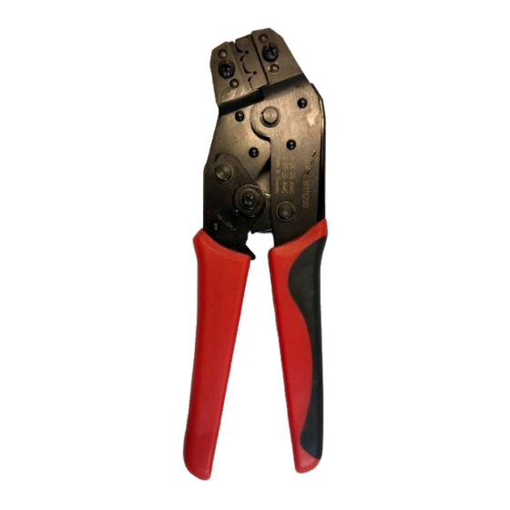
Hand and air tool repair kits are available through needs. Molex for customers who would like to repair their own tools. These kits can be found on the Molex website and are tool specific. Repair kit information can be found on the Molex data page for the specific hand and air tool part numbers on the Molex website. - Page 27 63811-1200 Hand Crimp Tool for “Sherlock” 2mm WTW and WTB Terminals HAND CRIMP TOOL Operating Instruction and Specification Sheet Order No. 63811-1200 FEATURES Œ Small handle spread which make this style tool ideally suited for end users Œ Ratchet with safety release that ensures consistent performance Œ...
-
Page 28: Operation
63811-1200 Hand Crimp Tool for “Sherlock” 2mm WTW and WTB Terminals PRE-STRIPPED WIRE OPERATION Open the tool by squeezing the handles together, at the end of the closing stroke, the ratchet mechanism will release the handles, and the hand tool will spring open. -
Page 29: Warranty
3. This tool is intended for standard conductor sizes. It may not give a good insulation crimp support for all insulation sizes. 4. Molex does not repair hand tools (see warranty above) The replacement parts listed are the only parts available for repair. If the handles or crimp tooling is damaged or worn, a new tool must be purchased. -
Page 30: Parts List
63811-1200 Hand Crimp Tool for “Sherlock” 2mm WTW and WTB Terminals PARTS LIST Item Number Order Number Description Quantity 63811-1275 Locator Assembly** 11-11-0324 Spring (Main) 11-11-0320 Spring (Ratchet) ** Not all tools are equipped with a locator or locator blade.
Need help?
Do you have a question about the 63811-1200 and is the answer not in the manual?
Questions and answers