Advertisement
Quick Links
Advertisement

Related Manuals for Carf-Models Sukhoi SU-27


Summary of Contents for Carf-Models Sukhoi SU-27
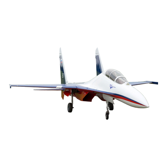
- Page 1 Sukhoi SU-27 / 30 Instruction Manual V 1.2...
- Page 2 However, as manufacturers, we at CARF-Models are not in a position to influence the way you build and operate your model, and we have no control over the methods you use to install, operate and maintain the radio control system components.
- Page 3 Attention! This jet aircraft is a high end product and can create an enormous risk for both pilot and spectators. If not handled with care and use according to the instructions. Make sure that you operate your SU-27/30 according to the laws and regulations governing model flying in the country of use.
- Page 4 However, if you think that some additional or different hardware should be included, please feel free to let us know. Email us : feedback@carf-models.com. We know that even good things can be made better!
- Page 5 Accessories: This is a list of suggested accessories which will help you to complete your project: 1 9 x Standard size digital servos with at least 25 kg (JR 8911 or similar*) 2 2 x 10mm digital servos with at least 6 kg (Savöx 0211MG, MKS 6625, or similar)* 3 1 x Pneumatic pack for speed brake (130650) 4 1 x Cockpit (360104) 5 1 x Tank set (360106)
- Page 6 Center of Gravity (CG) and rudder deflections: The CG is located 10-20mm in front of the big wing tube. 10-20mm Rudder deflections: The SU-27/30 is flown with tailerons only. Thus you have to mix elevator and aileron function. - Neutral position of the taileron is approximately 90-95mm from fuselage edge (see page 21) - Elevator up: 50mm (measured at the leading edge of the taileron) - Elevator down: 45mm (measured at the leading edge of the taileron) - Aileron up: 40mm (measured at the leading edge of the taileron)
-
Page 7: General Information
General information The fuselage and the wings are made of total area sandwich technology (TAVS) and are reinforced with carbon in the highly stressed areas. Carbon reinforced gear formers are installed and alligned. -
Page 8: Included Hardware
Included hardware Fuselage Pack Fin Pack Gear door Pack Taileron Pack Wing Pack Accessories... - Page 9 Slat servo installation Assemble the servo mount for the outer slat servo. Mark the exact position of the linkage on the outside of the servo cover. Then copy the mark to the inside of the servo cover. Glue the servo mount (with temporarily installed servo) in correct and centered position.
- Page 10 Slat servo installation Prepare the servo horns for both slat servos with a length of 14mm. Mount the servo horns with a servo 14mm tester right-angled. Then rotate both servos in this position (slat – in). Adjust the linkage for the outer servo to approx.
- Page 11 Slat servo installation Insert the linkage with a little Loctite from the servo side and screw it into the mounted clevis. Clip the clevis into the servo horn. It might be helpful to set the servo in a right-angled position again, remove the servo horn, connect it to the clevis and then permanently install the servo horn right-angled.
- Page 12 Slat servo installation As already done for the outer slat servo, glue 1 nut to the threaded rod and remove the clevis from that side. Mount the servo horn with a servo tester right-angled. Install the removed clevis to the inner horn of the slat.
- Page 13 Flap servo installation Assemble the servo mount for the flap servo exactly like done for the outer slat servo. Mark the exact position of the linkage on the outside of the servo cover, carry over to the inside, glue the servo mount with temporarily installed flap servo to the correct position and reinforce with epoxy and fiberglass...
- Page 14 Flap servo installation Prepare for the flap servos of both wing halves the servo horns with a length of 14mm. 14mm Mount the servo arms in center position (servo tester). Grind the corners of the servo mount for easier installation. Grind here Grind the lip-cover as shown on the photo for easier installation of the clevis.
- Page 15 Flap servo installation Mark the position of the linkage and grind the wooden reinforcement frame for maximum space as shown on the photo. Protect the wing surface first and install the servo as shown. Installing the flap servo is a bit tricky because the linkage crosses over from the bottom side of the wing to the top.
- Page 16 Vertical fins / servo installation Note: Even at the full scale version both fins are identical and not in mirror! Regular 15/16 mm servo: Mark the exact position of the linkage to the fin. If necessary mark areas which have to be cut to fit the servo and cut those areas out.
- Page 17 Vertical fins / servo installation Then add some silicone to the servo and permanently install it in its place. Note: The silicone is very important as it makes sure that the servo will not move in the servo frame. You will always be able to remove the servo by pulling it gently.
- Page 18 Vertical fins / fin installation The fins are connected with the fuselage by 2 solid carbon rods. For packing reasons the rods are not yet glued into the fuselage. Also because there are 2 different fin options available, slight tolerances can be caught and corrected in this work step.
- Page 19 Horizontal stab / servo installation 15° 15° 20mm Neutral Neutral For redundancy and flight safety each taileron should be controlled by 2 servos. To make the installation of the rods and the adjustments of the servos easy please use the included mounting jig which has the same dimension as the servo mounts in the fuselage.
- Page 20 Horizontal stab / servo installation The photo above shows how your dummy servo installation should look like. To start the fuselage installation remove the servos from the jig but leave the linkages on the servo arms, only disconnect the two servos by removing the clevis from the REAR servo.
- Page 21 Horizontal stab / stab installation Slide the taileron rods into the tailerons and secure them with the M3 bolt. Then Insert the assembly into the corresponding sleeve in the fuselage. Put the phenolic washer in place and screw the center bolt in with Loctite! This will hold the stab in place when it is bolted on to the rod.
- Page 22 Thrust pipe installation Drill 3 holes into the trust pipe and carbon entry cone. Bolt trust pipe and entry cone together. Glue the centring former for the into each nozzle. Right and left former should be at approx. the same position, measure around the distance and align accordingly.
- Page 23 Trust pipe installation Drill 2 holes 3mm intone flange of the aluminium brackets to mount to the wood board and 1 hole 3mm into the other flange to mount against the carbon entry cone. Cut the edge of one flange as seen on the photos.
- Page 24 Turbine, ECU and receiver installation Use an actual engine to align the entry cone properly. Then mount the turbine in centred and straight, aligned with to the trust pipe. To be safe, ask your turbine manufacture for the correct distance between rear edge of the engine’s exit nozzle and the front edge of the stainless steel thrust tube! At the engine sizes commonly used for this...
- Page 25 Fueltank, Hopper and turbine pump installation Both fuel tanks are made especially for the SU and fit perfectly into the fuselage. Make the internal tubing like the picture. Check the tubes, position of the smashing and the clunck. Build the hopper tank like the picture.
- Page 26 Fueltank, Hopper and turbine pump installation Install the tanks in the order shown in the following pictures. Use the reverse order o remove the tanks. Push both tanks towards the wing tube. Prepare the aluminium bracket as shown on the photo… …and the wood with the drive-in nut.
- Page 27 Fueltank, Hopper and turbine pump installation Then glue the 2 mount assemblies to each fuel tanks and to the bottom of the fuselage with Hysol or other epoxy glue. Don’t forget to sand the glueing surfaces properly and then let the glue set over night.
- Page 28 Turbine pump and ECU installation Engine and RC equipment placement is usually very much at the liking of the builder, but there are a few useful positions we found during practical flying. So we recommend to place the hopper tanks like shown in front of the nose gear former, where they are visible through the canopy opening.
- Page 29 Speed brake installation The operational speed brake is an option for this airplane, but it is highly recommended to be installed and used. The speed brake is very efficient and has no pitch up or down effects when deployed. A skilled use of the speed brake will always be the best option to control speed and sink rate during landing approaches, for formation flying and...
- Page 30 Speed brake installation Glue the brackets to the tanks at the correct position and reinforce with epoxy and a patch of fibreglass. The installed pneumatic cylinder in its extended position. The installed pneumatic cylinder in its retracted position. Cut a rectangular hole in the cover of the speed brake opening for the pneumatic cylinder like shown in the photo.
- Page 31 Landing Gear installation Start with the nose gear. Screw the nose gear with 2 self tapping sheet metal screws to the nose gear former. Check alignment and gear movement. It’s easy to correct at this time. Extend the front edge of the nose gear cutout slightly, so that the wheel passes without touching the edge.
-
Page 32: Gear Installation
Gear Installation The SU-27/30 gear is a complex piece of craftsmanship. The main gear turns 90 degree during the extending and retracting process. The space for the wheel is tight, so it is necessary to place the gear carefully and precisely into the fuselage’s gear mounts. - Page 33 Gear Installation Note: If it appears that you need to grind down some areas of the gear formers and you really cannot get the same effect by using spacers on the opposite side, there will be no choice but actually grinding a little off the gear formers. As long this is only 1-2 mm thickness, it will not harm the structural integrity.
- Page 34 Door Cylinders and Valve For the door cylinder installation mount under every bracket of the cylinder a 3mm plywood with small sheet metal screws. Cut the protruding tips off. Connect the airlines with sufficient length and secure them with thin safety wire if you feel that it’s necessary.
- Page 35 Door Cylinder and Valve Installation The CARF Pneumatic Completion kit consists of 2 pcs 2-way valves for retracts and gear doors and 1 pc 1-way valve for wheel brakes. As the speed brake is such a highly recommended accessory, we describe the valve installation of the speed brake pneumatic kit in this manual as well.
- Page 36 Cockpit installation / overview The cockpit is a optional accessory, but its installation is shown in this manual. The SU- 27/30 cockpit is a basic cockpit kit, which can be enhanced individually if required. All parts are hand laminated composite parts: 2 trays, 2 dash boards with covers and 2 seats.
-
Page 37: Cockpit Installation
Cockpit installation Cut the cockpit tubs like this to have a 10mm edge left. On the photo left is the rear tub and right is front tub. Shorten the front tub on the upper side to 180mm length and on the bottom side to 130mm. - Page 38 Cockpit installation Glue a scrap wood with velcro to the front edge of the rear cockpit tub as shown on the photo. Stick some Velcro on it. The rear cockpit tube is overlapping the front cockpit tub. See the top view on both cockpit tubs on the right.
- Page 39 Cockpit installation A little wooden lip glued to the rear wall of the front tub supports and stabilizes the instrument holder a lot. Cut the front dash board cover like shown on the above photo. Glue the panel into the cover and cut the instrument panel like shown on the right.
- Page 40 Cockpit installation Stopper installed. Place the seats like the measures from cockpit overview page. Cockpit front. Cockpit rear. Feel free to add details as you wish, then paint the cockpit. Finally cut out and apply the instrument stickers accordingly.
-
Page 41: Canopy Installation
Canopy installation First roughly cut the canopy, so that it could be put from the outside on the canopy frame, which should be mounted on the fuselage. Mark the exact cut lines then. Allow 3-5 mm overlap for glue surface. Do this for the main canopy and the front canopy glass. - Page 42 Antenna and pitot tube installation Check pictures for correct position (right side of the fuselage gets 1 big pitot tub only). See next page how you can install them removable. There are two versions of the infrared camera. The SU-27 has it mounted in the center, in front of the wind screen.
- Page 43 Antenna and pitot tube installation There are plenty of methods to make an antenna removable, which otherwise would be at risk to be broken off during transport. Drill 1 or 2 holes into each antenna and tap M3. Reinforce the fuselage from inside with a piece of plywood or fiberglass to screw on the antennas.
- Page 44 Thank you! Your CARF-Models Team...
Need help?
Do you have a question about the Sukhoi SU-27 and is the answer not in the manual?
Questions and answers