Table of Contents
Advertisement
Quick Links
HS-6036
Socket 370 Celeron
™
Coppermine
•VGA •133MHz FSB•ATA/33/66•LAN•
•PC/104•IrDA•USB•WDT•H/W Monitor•
•PICMG Industrial Single Board Computer•
HS-6036V
Socket 370 Celeron
™
Coppermine
•VGA •133MHz FSB•ATA/33/66•
•PC/104•IrDA•USB•WDT•H/W Monitor•
•PICMG Industrial Single Board Computer•
™
/
™
/Tualatin
™
/
™
/Tualatin
Advertisement
Chapters
Table of Contents

Related Manuals for Boser HS-6036


Summary of Contents for Boser HS-6036
- Page 1 HS-6036 ™ Socket 370 Celeron ™ ™ Coppermine /Tualatin •VGA •133MHz FSB•ATA/33/66•LAN• •PC/104•IrDA•USB•WDT•H/W Monitor• •PICMG Industrial Single Board Computer• HS-6036V ™ Socket 370 Celeron ™ ™ Coppermine /Tualatin •VGA •133MHz FSB•ATA/33/66• •PC/104•IrDA•USB•WDT•H/W Monitor• •PICMG Industrial Single Board Computer•...
- Page 2 Trademarks BOSER is a registered trademark of BOSER Technology Co., Ltd. ISB is a registered trademark of BOSER Technology Co., Ltd. Intel is a registered trademark of Intel Corporation.
-
Page 3: Table Of Contents
Contents HS-6036 ......................1 HS-6036V....................II GENERAL INFORMATION ................3 1.1 M ..................4 AJOR EATURES 1.2 S ..................5 PECIFICATIONS 1.3 D ...................7 ELIVERY ACKAGE HARDWARE INSTALLATION ................8 2.1 C .............8 AUTION OF TATIC LECTRICITY 2.2 C ......9 AUTION ON NPACKING AND EFORE NSTALLATION 2.3 HS-6036’... - Page 4 3.14 P /104 B ..............30 ONNECTION AWARD BIOS SETUP..................32 4.1 M ....................33 4.2 S CMOS S ...............34 TANDARD ETUP 4.3 A CMOS F ..............35 DVANCED EATURES 4.4 A ..............36 DVANCED HIPSET EATURES 4.5 I ..............37 NTEGRATED ERIPHERALS 4.6 P ..............39 OWER ANAGEMENT ETUP...
-
Page 5: General Information
Chapter-1 General Information The HS-6036 is a 100MHz FSB PICMG Bus System that also supports ® 133MHz clock. It features Socket 370 for Intel Celeron™/Coppermine Tualatin Industrial Single Board CPU Card and functions that make it an ideal all-in-one industrial single board computer. HS-6036 uses the Intel 440BX chipset that offers better stability than other 133MHz FSB based systems in the ISA bus and software compatibility. -
Page 6: Major Features
1.1 Major Features ® Socket 370 for Intel Celeron /Coppermine /Tualatin 266MHz~1.2GHz CPU Intel 82443BX/SMSC SLC90E66 system chipset 100MHz FSB provides up to 133MHz FSB Four DIMM sockets with a max. capacity of 1GB Winbond W83977 super I/O chipset Fast PCI ATA/33/66 IDE controller Two RS-232 serial ports PC/104 Bus connector SiS 305 3D display controller... -
Page 7: Specifications
1.2 Specifications ® CPU:Socket 370 for Intel Celeron /Coppermine /Tualatin 266MHz~1.2GHz CPU Bus Interface:PICMG Bus Bus Clock Rate:100MHz FSB up to 133MHz FSB Memory:Four DIMM sockets provides up to 1GB ® Chipset:Intel 82443BX/SMSC SLC90E66 I/O Chipset:Winbond W83977 VGA:SiS 305 with 16MB memory support hardware DVD IDE:Four IDE disk drives support ATA/33/66 and with transfer rates of up to 33/66MB/sec Floppy:Support up to two floppy disk drives... - Page 8 Watchdog Timer:Set 1, 2, 10, 20, 110, 220 seconds activity trigger with Reset or NMI CMOS:DS12C887 or equivalent device DMA Channels:7 Interrupt Levels:15 Maximum Power Consumption:+5V@8A(933MHz)、+12V@120mA、 -12V@50mA Operating Temperature:0~60°C Hardware Monitor:Winbond W83783S Board Size:33.6 x 12.1 cm...
-
Page 9: Delivery Package
1.3 Delivery Package The delivery package of HS-6036 includes all following items: One HS-6036 Industrial Single Board Computer One Printer Ports Bracket Flat Cable One com port Bracket Flat Cable Two IDE port Flat Cable One FDD port Flat Cable Utility CD User’s Manual... -
Page 10: Hardware Installation
Hardware Installation This chapter provides the information on how to install the hardware of HS-6036. First, proceed with sections 1.3, 2.1 and 2.2 to check the delivery package. Then, proceed with the jumpers setting of switches, Watch-Dog Timer and the DiskOnChip address selection etc. -
Page 11: Caution On Unpacking And Before Installation
2.2 Caution on Unpacking and Before Installation First, follow all the necessary steps of section 2.1 to protect the HS-6036 from electricity discharge. Refer to section 1.3 to check the delivery package again with following steps: 1. Unpack the HS-6036, Store well all packing materials, manual and diskette, etc. -
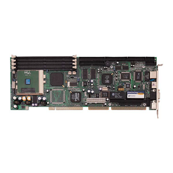
Page 12: Hs-6036'S Layout
2.3 HS-6036’s Layout... -
Page 13: Quick Listing Of Jumpers
2.4 Quick Listing of Jumpers ............... P.21 ESET PIN AGP VGA C ..........P.14 LOCK ELECT CPU H ..........P.14 LOCK ELECT CMOS..............P.14 LEAR A JP8(1-4) ..........P.18 DDRESS JP8(5-10) T ......... P.15 IME OF ATCH ELECT ...... P.15 ATCH IMER CTIVE... -
Page 14: Quick Listing Of Connectors
2.5 Quick Listing of Connectors ATX P ............P.19 OWER WITCH ............. P.21 PEAKER ONNECTOR HDD LED ............... P.21 ................. P.21 EYLOCK ........... P.26 EYBOARD ONNECTOR IR C ..............P.27 ONNECTOR FAN C ............P.19 ONNECTOR ............P.29 ONNECTOR IDE C .......... -
Page 15: Jumper Setting Description
2.6 Jumper Setting Description A jumper pin-set is ON as a shorted circuit with a plastic cap inserted over two pins. A jumper pin-set is OFF as a open circuit with a plastic cap inserted over one or no pin(s) between pins. The below figure 2.2 shows the examples of different jumper pin-set setting as ON or OFF in this manual. -
Page 16: Setting The Cpu Host Clock Frequency
CPU Type JP10 *Tualatin Coppermine 2.8 Setting the RTC Configuration The HS-6036 provides a setting for the selection of the RTC Clear Jumper by JP6 setting as follows: CMOS Setting of JP6(Only for DS12B887): CMOS Clear Jumper Normal * OFF... -
Page 17: System Memory Dram
2.9 System Memory DRAM The HS-6036 provides a wide SDRAM memory support with four DIMM sockets request the access time should meet PC-133 standard (if use 133MHz FSB). The maximum capacity of the on board memory is 1GB. Use memory module of the same brand and size to avoid instability due to different access time. - Page 18 must constantly proceed a Refresh cycle to Watchdog Timer before its period setting comes ending of every 1, 2, 10, 20, 110 or 220 seconds which pre-setting by JP8(5-10). If the Refresh cycle does not active before Watchdog Timer period cycle, the on board Watchdog Timer architecture will issue a Reset or NMI cycle to the system.
-
Page 19: Vga Controller
DB15 internal VGA connector, CN24 (see below). Another header is 5X2 internal VGA connector, CN20. The HS-6036 has built-in a SiS 503 VGA controller with on chip 16MB memory that supports resolutions up to 1024x768x16M colors. CN20 : VGA connector (5x2 Header) PIN NO. -
Page 20: Diskonchip Address Setting
DiskOnChip (D.O.C.) to avoid the mapping area with any other memory devices. If you have another extra memory devices in the system with the same memory, neither the HS-6036 nor the extra memory devices will function normally. Please set both at different memory address mapping. -
Page 21: Connection
This chapter gives all necessary information of the peripheral connections, switches and indicators. 3.1 Power and FAN Connectors The HS-6036 provides three 3pin FAN out connector - CN6, FN2, FN3. S1 is the ATX Power Switch, CN10 is the ATX Power Connector, CN11 is the 5pin ATX Power Connector. - Page 22 The HS-6036 supports ATX Power function by CN10. The connector of CN11 can control the 5pin ATX Power via the extension cable from the Backplane. CN10 Description CN10 Description -12V PS_ON 5VSB +12V FN2, FN3 : 3pin FAN Connector PIN NO.
-
Page 23: Ide' Sled, Keylock And Reset Button
3.2 IDE's LED, Keylock and Reset Button The HS-6036 has one LED indicates out power-on status. And the following provides the pin information for IDE's LED indicator, Keylock and Reset Button connections from CN2, CN3 and JP1. If user doesn’t need keylock function, CN3 could be use for power led connect pin-1 + pin-3 OR pin-1 + pin-5. -
Page 24: Pci E-Ide Drive Connector
3.4 PCI E-IDE Drive Connector Two standard 40pin header daisy chain drive connectors provide as CN8 and CN9 with following pin assignment. A total four IDE disk (Integrated Device Electronics) drivers may be connected. CN8: Primary IDE Connector PIN NO. Description PIN NO. -
Page 25: Cn9 Secondary Ide Connector
CN9: Secondary IDE Connector PIN NO. Description PIN NO. Description Reset DATA 7 DATA 8 DATA 6 DATA 9 DATA 5 DATA 10 DATA 4 DATA 11 DATA 3 DATA 12 DATA 2 DATA 13 DATA 1 DATA 14 DATA 0 DATA 15 IOW# IOR#... -
Page 26: Parallel Connector
3.5 Parallel Connector A standard 26pin flat cable driver connector is provided as CN16 with the following pin assignment for connection to parallel printer. CN16: Parallel Connector PIN NO. Description PIN NO. Description Strobe DATA 0 DATA 1 DATA 2 DATA 3 DATA 4 DATA 5... -
Page 27: The Floppy Disk Drive Connector
3.6 The Floppy Disk Drive Connector A standard 34pin header daisy-chain drive connector is provided as CN12 with following pin assignment. A total two FDD drivers may be connected. CN12 : FDD Connector PIN NO. Description PIN NO. Description Reduce Write Index# Motor Enable A# Drive Select B#... -
Page 28: Serial Ports Connectors
3.7 Serial Ports Connectors The HS-6036 offers two high speeds 16C550 compatible UART with Read/Receive 16byte FIFO serial ports with two internal 10pin header. CN17, CN18 : COM1, COM2 Connector (5x2 Header) PIN NO. Description PIN NO. Description 3.8 Keyboard Connectors... -
Page 29: Ps/2 6 Pin Mini Din Mouse Connector
PIN NO. Description Keyboard Data Keyboard Clock 3.9 PS/2 6pin Mini Din Mini Connector The HS-6036 provides an external PS/2 mouse connector at CN23 and 4pin connector at CN19. CN23 : PS/2 6pin Mini Din Mouse Connector PIN NO. Description... -
Page 30: Ir Connector
CN5 : IrDA Connector PIN NO. Description FIRRX IRRX IRTX 3.11 USB Ports Connector The HS-6036 provides two internal 8pin USB ports connectors. Please refer to the following detail pin information. CN15:USB Connector PIN NO. CN15 PIN NO. CN15 BD0-... -
Page 31: Lan Interface Connector
3.12 LAN Interface Connector The HS-6036 provides RJ-45 10/100 Based LAN interface connector. Please refer to the following detail of pin information. CN22 : RJ-45 Connector PIN NO. CN22 R/C GND R/C GND R/C GND R/C GND 3.13 I C Bus Interface Connector... -
Page 32: Pc/104 Bus Connection
3.14 PC/104 Bus Connection The HS-6036’s PC/104 expansion bus allows you to connect all kind of PC/104 modules. The PC/104 bus has already become the industrial embedded 16bit PC standard bus. You can easily install over thousands type of PC/104 modules from hundreds of vendors in the world. - Page 33 CN13&CN14 : PC/104 Expansion Bus (CN13 = 64pin female connector; CN14 = 40pin female connector.) CN13 CN13 CN14 CN14 Row A Row B Row D Row C IOCHECK* 34 RESETDRV MEMCS16* 22 SBHE* IOSC16* LA23 IRQ9 IRQ10 LA22 IRQ11 LA21 DRQ2 IRQ12 LA20...
-
Page 34: Award Bios Setup
Chapter-4 AWARD BIOS Setup The HS-6036 uses the Award PCI/ISA BIOS for the system configuration. The Award BIOS setup program is designed to provide the maximum flexibility in configuring the system by offering various options which could be selected for end-user requirements. -
Page 35: Main Menu
4.1 Main Menu Once you enter the Award BIOS CMOS Setup Utility, the Main Menu will appear on the screen. The Main Menu allows you to select from several setup functions and two exit choices. Use the arrow keys to select among the items and press <Enter> to enter the sub-menu. -
Page 36: Standard Cmos Setup
4.2 Standard CMOS Setup The Standard Setup is used for the basic hardware system configuration. The main function is for Data/Time and Floppy/Hard Disk Drive settings. Please refer to the following screen for the setup. When the IDE hard disk drive you are using is larger than 528MB, please set the HDD mode to LBA mode. -
Page 37: Advanced Cmos Features
4.3 BIOS Features Setup This section allows you to configure your system for the basic operation. You have the opportunity to select the system’s default speed, boot-up sequence, keyboard operation, shadowing and security. CMOS Setup Utility-Copyright ©1984-2001 Award Software Advanced CMOS Features Item Help Virus Warning [Disabled]... -
Page 38: Advanced Chipset Features
4.4 Chipset Features Setup This section allows you to configure the system based on the specific features of the installed chipset. This chipset manages bus speeds and the access to the system memory resources, such as DRAM and the external cache. It also coordinates the communications between the conventional ISA and PCI buses. -
Page 39: Integrated Peripherals
4.5 Integrated Peripherals The IDE hard drive controllers can support up to two separate hard drives. These drives have a master/slave relationship which is determined by the cabling configuration used to attach them to the controller. Your system supports two IDE controllers--a primary and a secondary--so you can install up to four separate hard disks. -
Page 40: Power Management Setup
4.6 Power Management Setup The Power Management Setup allows user to configure the system for saving energy in a most effective way while operating in a manner consistent with his own style of computer use. CMOS Setup Utility-Copyright ©1984-2001 Award Software Power Management Setup Item Help ACPI function... -
Page 41: Pnp/Pci Configuration Setup
4.7 PnP/PCI Configuration Setup In this section, the PnP/PCI configuration setup allows you to configure the ISA and PCI devices installed in your system by manually or auto. CMOS Setup Utility-Copyright ©1984-2001 Award Software PnP/PCI Configurations Item Help PNP OS Installed [Yes] Menu Level Reset Configuration Data... -
Page 42: Pc Health Status
4.8 PC Health Status CMOS Setup Utility-Copyright ©1984-2001 Award Software PC Health Status Item Help CPU Warning Temperature [Disabled] Menu Level Current System Temp. Current CPU1 Temperature Current CPUFAN1 Speed Current CPUFAN2 Speed Current CPUFAN3 Speed Vcore +3.3V +5 V +12 V -12 V Shutdown Temperature... -
Page 43: Frequency/Voltage Control
4.9 Frequency/Voltage Control CMOS Setup Utility-Copyright ©1984-2001 Award Software Frequency/Voltage Control Item Help Auto Detect DIMM/PCI Clk [Enabled] Menu Level CPU Clock/Spread Spectrum [Default] :Move Enter:Select + / - /PU/PD:Value F10:Save ESC:Quit F1:General Help F5:Previous Values F6:Fail-Safe Defaults F7:Optimized Defaults... -
Page 44: Software Utilities
Chapter-5 Software Utilities This chapter provides the detailed information of VGA、LAN and SMSC DMA66 function. How to install the configuration is also included. Section include: VGA DRIVER INSTALLATION NETWORK DRIVER INSTALLATION SMSC DRIVER INSTALLATION... - Page 45 5.1 VGA DRIVER INSTALL FOR WIN95&98 1. Enter Explorer and move to source location 2. Execute “Setup” 3. Follow the installation procedure 4. Re-start Computer and driver will be properly installed...
-
Page 48: Vga Driver Install For Win Nt4.0
5.2 VGA DRIVER INSTALL FOR WIN NT4.0 1. Click the Start button, then go to Setting and click on Control Panel. 2. Click on Display icon to start the Display Properties Window. 3. Click on the Settings tab, and then click on Display Type. 4. -
Page 52: Vga Driver Install For Win 2000
5.3 VGA DRIVER INSTALL FOR WIN 2000 1. Click the Start button, then go to Setting and click on Control Panel. 3. Click on Display icon to start the Display Properties Window. 4. Click on the Settings tab, and then click on Display Type. 5. -
Page 56: Network Driver Install For Win98
5.4 NETWORK DRIVER INSTALL FOR WIN98 1. Click Start, then Settings, in the “Setting” select Control panel. 2. Start the network applet program. 3. In the Network window, click Add. 4. In the Select Network Component Type, select Adapter then click Add. -
Page 60: Network Driver Install For Win Nt4.0
5.5 NETWORK DRIVER INSTALL FOR WIN NT4.0 1. Click the Start button, then go to Settings and click on Control Panel. 2. Click on the Network icon to start the Network window. Click on the Adapters tab, and then click on Add. 3. -
Page 68: Smsc Driver Install For Win 95 & Win 98
5.6 SMSC INSTALL FOR WIN95 & WIN98 1. Click Start, then Setting, in the “Setting” select system 2. Select PCI Bridge, run properties 3. Select update device driver 4. Select specify a location (if in driver D:\IDE) 5. After restart, check on the SMSC driver, the properties of the driver should look similar to the following figure... -
Page 73: Smsc Driver Install For Win 2000
5.7 SMSC INSTALL FOR WIN2000 1. Select My Computer, type mouse right butter, click device 2. Click other PCI Bridge Device, upgrade new driver 3. Enter source path and select “90E66USB” 4. Re-start system and driver will be properly installed...
Need help?
Do you have a question about the HS-6036 and is the answer not in the manual?
Questions and answers