Table of Contents
Advertisement
Quick Links
Advertisement
Table of Contents

Subscribe to Our Youtube Channel
Related Manuals for Boser HS-4010


Summary of Contents for Boser HS-4010
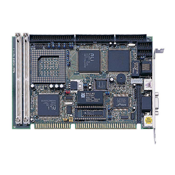
- Page 1 HS-4010 Half 486 Little Board 10 Base-T Network, Flat Panel, VGA Control.
- Page 2 Trademarks BOSER is a registered trademark of BOSER Technology Co., Ltd. Intel is a registered trademark of Intel Corporation. Award is a registered trademark of Award Software, Inc.
-
Page 3: Table Of Contents
ONTENTS HS-4010........................1 GENERAL INFORMATION..................3 1.1 M ....................4 AJOR EATURES 1.2 S ......................5 PECIFICATIONS 1.3 D ....................7 ELIVERY ACKAGE HARDWARE INSTALLATION................... 8 2.1 C ................8 AUTION OF TATIC LECTRICITY 2.2 C ........9 AUTION ON NPACKING AND EFORE NSTALLATION 2.3 HS-4010’... - Page 4 4.1 M ......................35 4.2 S CMOS S ..................36 TANDARD ETUP 4.3 BIOS F ..................37 EATURES ETUP 4.4 C ..................38 HIPSET EATURES ETUP 4.5 P ................39 OWER ANAGEMENT ETUP 4.6 P P/PCI C ..............40 ONFIGURATION ETUP 4.7 I ................41 NTEGRATED ERIPHERAL ETUP 4.8 P ....................42...
-
Page 5: General Information
Chapter-1 General Information The HS-4010 is an all-in-one half size industrial single board with design in Novell NE2000 compatible 16 bits ISA bus Ethernet, provides 10 BASE-T for directly network automation demand. Supports for various 40-133 MHz 80486SX/DX/DX2/DX4, 5x86 CPUs with 32-bit data bus and processing ability. -
Page 6: Major Features
1.1 Major Features ?? 80486SX/DX/DX2/DX4, 5x86 CPU supported. ?? ALi 1487/1489 chipset. ?? Supports DRAM up to 64 MB. ?? Fast PCI enhanced IDE controller supports two IDE drives. ?? Two high-speed serial RS-232 ports (supports 16C550 UART with 16-byte FIFO). ?? One enhanced bi-directional parallel port supports SPP/EPP/ECP. -
Page 7: Specifications
1.2 Specifications ?? CPU: 80486SX/DX/DX2/DX4/5X86. ?? Bus interface: ISA bus ?? Chipset: ALi 1487/1489 ?? Data bus: 32-bit ?? Processing ability: 32-bit ?? PCI Flat Panel / VGA Controller: VGA Chipset with 1 MB memory interface to color and monochrome Single Drive (SS) and Dual Drive (DD) STN, TFT &... - Page 8 support up to 72MB Flash memory disk.
-
Page 9: Delivery Package
?? Operating temperature: 0-55°C (CPU need cooler). Board size: 8" (L) x 5.75" (W) (203mm x 146mm). 1.3 Delivery Package The delivery package of HS-4010 includes all following items: HS-4010 Industrial Single Board Printer port Flat Cable IDE port Flat Cable... -
Page 10: Hardware Installation
Hardware Installation This chapter provides the information on how to install the hardware of HS-4010. At first, please follow up sections 1.3, 2.1 and 2.2 in check the delivery package and carefully unpacking. Following after, the jumpers setting of switch, watchdog timer, and the DiskOnChip? address selection. -
Page 11: Caution On Unpacking And Before Installation
With refer to section 1.3, please check the delivery package again with following steps: 1. Unpacking the HS-4010, keep well storage of all packing material, manual and diskette etc. if has. 2. Is there any components lose or drop from the board? DO NOT INSTALL IF HAPPENED. -
Page 12: Hs-4010' S Layout
2.3 HS-4010’ s Layout... -
Page 13: Quick Listing Of Jumpers
2.4 Quick Listing of Jumpers — JP2, 3, 4, 5, 9,10,11,12,13 for CPU type setting — CPU clock selection — CPU's Vcore voltage level selection setting — CPU's operating voltage selection setting — PCI clock setting — JP14 for AMD CPU type selection —... - Page 14 CN17: KEYBOARD CONNECTOR (MINI DIN TYPE)
-
Page 15: Jumper Setting Description
2.6 Jumper Setting Description A jumper pin-set is ON as a shorted circuit with a plastic cap inserted over two pins. A jumper pin-set is OFF as a open circuit with a plastic cap inserted over one or no pin(s) between pins. The below figure 2.2 shows the examples of different jumper pin-set setting as ON or OFF in this manual. -
Page 16: Setting The Cpu Of Hs-4010
2.7 Setting the CPU of HS-4010 The HS-4010 provides all possibility in jumper setting for wide using all types of 486 series CPU with JP1, JP2, JP3, JP4, JP5, JP7, JP8, JP9 and JP10 setting as following: CPU Clock Setting JP3 JP5 JP4 JP9 JP1 1.IntelDX4™... - Page 17 JP14 DESCRIPTION AMD DX2 *OFF AMD DX4 JP15 used to synchronize the CPU clock with the CPU type. Please set the CPU clock with JP15, JP1 and JP8 jumpers according to the base CPU speed. CPU clock select JP15 DESCRIPTION OFF, OFF 25 MHz *1-2, 3-4...
-
Page 18: System Memory Dram
2.8 System Memory DRAM The HS-4010 provides a wide range on-board DRAM memory sizes from 1 MB to 16 MB by using 1, 2, 4, 8 or 16MB 72-pin SIMMs (Single In-Line Memory Modules) with access time should be 70 n-second or faster. - Page 19 *1 sec 2 sec 10 sec 20 sec 110 sec 220 sec The Watch-dog timer is disabled after the system Power-On. The watch-dog timer can be enabled by a Enable cycle with reading the control port (443H), a Refresh cycle with reading the control port (443H) and a Disable cycle by reading the Watch-dog timer disable control port (043H).
-
Page 20: Vga Controller
Up to 4096 different colors can be displayed on passive STN LCDs and up to 16 M colors on 24-bit active matrix LCDs. The HS-4010 uses C&T 65550 chipset. Provides 2.0 mm pitch 44-pin on-board internal connector for flat panel connection; and a external DB15 analogy R.G.B. -
Page 21: Diskonchip? Address Setting
2.13 DiskOnChip? Address Setting The HS-4010 provides a U8 socket for install the DiskOnChip? module. A JP19 may select the starting memory address of the DiskOnChip? (D.O.C.) for avoid the mapping area with any other memory devices. If you have another extra memory devices in the system with the same memory, neither the HS-4010 nor the extra memory devices will function normally. -
Page 22: Connection
Chapter-3 Connection This chapter gives all necessary information of the peripheral's connections, switches and indicators. 3.1 The Floppy Disk Drive Connector A standard 34-pin header daisy-chain driver connector provides as CN6 with following pin assignment. Total two FDD drivers may connect. CN6 : FDD CONNECTOR PIN NO. -
Page 23: Pci E-Ide Drive Connector
3.2 PCI E-IDE Drive Connector A standard 40-pin header daisy-chain driver connector provides as CN9 with following pin assignment. Total two IDE (Integrated Device Electronics) drivers may connect. CN5(IDE 1) : Primary IDE Connector PIN NO. DESCRIPTION PIN NO. DESCRIPTION RESET GROUND DATA 7... -
Page 24: Parallel Port Connector
3.3 Parallel Port Connector A standard 26-pin flat cable driver connector provides as CN1 with following pin assignment for connection to parallel printer. CN1 : Parallel Port Connector PIN NO. DESCRIPTION PIN NO. DESCRIPTION STROBE DATA 0 DATA 1 DATA 2 DATA 3 DATA 4 DATA 5... -
Page 25: Serial Ports Connectors
3.4 Serial Ports Connectors The HS-4010's CN11and 12 headers provides two high speeds NS16C550 compatible UARTs with Read/Receive 16 byte FIFO serial ports. Please see the following pin assignment. With the delivery package, user may uses the 10-pin COM cable for plug into CN11 and 12 for get COM1 to COM2 connection. -
Page 26: Keyboard Connector
3.5 Keyboard Connector The HS-4010 provides a 6-pin mini din connector CN17 for connection to Keyboard devices. CN17 : 6-pin Mini Din Keyboard Connector PIN NO. DESCRIPTION PIN NO. DESCRIPTION KB-DATA KB-CLK 3.6 Power's LED, FAN and Key-Lock Connectors The CN9 provides both Power's LED and Key-Lock connector as following pin assignment. -
Page 27: Ps/2 Mouse Irq12 Selection Connector
3.8 PS/2 Mouse IRQ12 Selection Connector The HS-4010 has an on-bard PS/2 mouse which using IRQ12. If you do not use the PS/2 mouse and wish to assign IRQ12 for other purposes, you should setting the JP17 to disconnect PS/2 interrupt from IRQ12. -
Page 28: Fast Ethernet Connector
3.11 Fast Ethernet Connector The Fast Ethernet controller provides with 16-bit performance, ISA bus master capability, and full compliance with IEEE 802.3 10Base-T specifications. For 10Base-T RJ-45 operation, please connect the network connection by plugging one end of the cable into the RJ-45 to CN13 Connector. CN13 : Ethernet Connector PIN NO. -
Page 29: Flat-Panel Connector
3.12 Flat-Panel Connector The HS-4010 provides a 44-pin 2.0 mm pitch header connector (CN8) for Flat panel connection. The information here also provides some pin information samples to Panel Sharp LM64183P, LM64C35P & LM64C142 and NEC NL8060AC26 ,Sharp LQ64D34. +12V... -
Page 30: Connections For Four Standard Lcds
3.13 Connections for four standard LCDs Connections to Sharp LM64183P (640 x 480 DSTN MONO LCD) Sharp LM64P83 HS-4010 CN10 Pin name Pin name CN1-1 CN1-2 CN1-3 SHFCLK CN1-4 DISP CN1-5 CN1-6 CN1-7 -17 V (external power) CN1-8 CN1-9 CN1-10... - Page 31 Connections to Sharp LM64C35P (640 x 480 DSTN STN Color) Sharp LM64C35P HS-4010 CN10 Pin name Pin name CN1-1 CN1-2 CN1-3 CN1-4 CN1-5 CN1-6 CN1-7 CN1-8 CN1-9 CN1-10 SLFCHK CN1-11 CN1-12 Vcon Contrast Adjust CN1-13 CN1-14 CN1-15 CN1-16 CN1-17 CN1-18...
- Page 32 Connections to NEC NL8060AC26 (800 x 600 TFT Color) NEC NL8060AC26 HS-4010 CN10 Pin name Pin name CN1-1 CN1-2 Dot Clock SHFCLK CN1-3 CN1-4 Hsync CN1-5 Hsync CN1-6 CN1-7 CN1-8 CN1-9 CN1-10 CN1-11 CN1-12 CN1-13 CN1-14 CN1-15 CN1-16 CN1-17 CN1-18...
- Page 33 CN1-39 PVcc PVcc CN1-40 PVcc PVcc CN1-41 MODE...
- Page 34 Connections to Sharp LM64C142 (640 x 480 DSTN STN Color) Sharp LM64C142 HS-4010 CN10 Pin name Pin name CN1-1 CN1-2 CN1-3 SHFCLK CN1-4 DISP CN1-5 PVdd CN1-6 PVss CN1-7 PVee +27 V (external power) CN1-8 CN1-9 CN1-10 CN1-11 CN1-12 CN1-13...
- Page 35 Connections to Sharp LQ64D34 (640 x 480 TFT Color) Sharp LQ64D34 HS-4010 CN10 Pin name Pin name CN1-1 CN1-2 SHFCLK CN1-3 HSYNC CN1-4 VSYNC CN1-5 CN1-6 CN1-7 CN1-8 CN1-9 CN1-10 CN1-11 CN1-12 CN1-13 CN1-14 CN1-15 CN1-16 CN1-17 CN1-18 CN1-19 CN1-20...
-
Page 36: Award Bios Setup
AWARD BIOS Setup For maintain the HS-4010's basic input/output system operating, the HS-4010 is now using AWARD BIOS for the system configuration and operation. The BIOS's setup program is designed to provide the maximum flexibility in configuring the system by offering various optional which allowing for select and meet all of the end-user requirements. -
Page 37: Main Menu
4.1 Main Menu Once when you enter the AWARD BIOS CMOS Setup Utility, the first prompt out screen is the BIOS's Main Menu. From the Main Menu, the BIOS allow you to select from several setup functions and two exit choices. -
Page 38: Standard Cmos Setup
4.2 Standard CMOS Setup The Standard Setup is used for the basic hardware system configuration. The main function is for Data/Time and Floppy/Hard Disk Drive settings. Please refer to the following screen for this setup. When the IDE hard disk drive you are using is larger than 528MB, please set the HDD mode to LBA mode. -
Page 39: Bios Features Setup
4.3 BIOS Features Setup This advanced setup is designed for the customers to achieve the highest performance of the HS-4010 board. As for normal operations, customers don't have to change any default settings. The default setting is pre-set for most reliable operations. Please refer to the following screen for the Advanced Setup. -
Page 40: Chipset Features Setup
4.4 Chipset Features Setup The section allow you to configure the system based on the specific feature of the installed chipset. This chipset manages bus speeds and the access to the system memory resources, such as DRAM and external cache. It also coordinates the communications between the conventional ISA and PCI buses. -
Page 41: Power Management Setup
4.5 Power Management Setup The Power Management Setup allows user to configure the system for save energy in a most effective way while operating in a manner consistent with his own style of computer use. Power Management Setup Power Management : Disabled IRQ5 (LPT2) : ON... -
Page 42: Pnp/Pci Configuration Setup
4.6 PnP/PCI Configuration Setup In this section, the PnP/PCI configuration setup allows you to configure the ISA and PCI devices installed in your system by manually or auto. PnP BIOS Auto- configuration : Disabled CPU to PCI Write Buffer : Enabled CPU to PCI Byte Merge : Enabled PCI to DRAM Buffer... -
Page 43: Integrated Peripheral Setup
4.7 Integrated Peripheral Setup For completed all input and output devices (i.e. FDD Drivers, IDE Drivers, Serial Ports, IR and Parallel Port), please refer to the following example. Integrated Peripherals Setup OnChip IDE LocalBus IDE : Enabled IDE Buffer for Dos & Win : Enabled The 2nd Channel IDE : Enabled... -
Page 44: Panel Type Select
4.8 Panel Type Select User can select the different type of LCD panel by change the value of “LCD Panel Type“ under the integrated peripherals setup. The default setting is “Panel 5” , according with different usage, user might change the value from 1 to 70, as list as the above table. Default BIOS Panel Types No Resolution Data... -
Page 45: A Brief Browse Of 10 Base-T Lan Rtl-8019'S Installation Software
A Brief Browse of 10 base-T LAN RTL-8019’ s Installation Software The Boser HS-4010 provides an on board 16-bit ISA 10 base-T Ethernet LAN interface RJ-45 connection for easy using the HS-4010 486 Little All-in-one L/VGA Industrial Single Board in connection to-with Novell NE2000 compatible LAN network system.
Need help?
Do you have a question about the HS-4010 and is the answer not in the manual?
Questions and answers