
Subscribe to Our Youtube Channel
Related Manuals for Boser HS-2601


Summary of Contents for Boser HS-2601
- Page 1 HS-2601 Celeron /Coppermine VGA LAN • CRT/Panel•SODIMM•LAN•PC/104•Mini PCI• • Flash Disk•IrDA•USB•Single +5V• •Embedded35 Industrial Single Board Computer•...
- Page 2 Trademarks BOSER is a registered trademark of BOSER Technology Co., Ltd. ISB is a registered trademark of BOSER Technology Co., Ltd. Intel is a registered trademark of Intel Corporation.
-
Page 3: Table Of Contents
Contents HS-2601 ......................1 GENERAL INFORMATION ................3 1.1 M ..................4 AJOR EATURES 1.2 S ..................5 PECIFICATIONS 1.3 D ...................6 ELIVERY ACKAGE HARDWARE INSTALLATION ................7 2.1 C .............7 AUTION OF TATIC LECTRICITY 2.2 C ......8 AUTION ON NPACKING AND EFORE NSTALLATION 2.3 HS-2601’... - Page 4 AWARD BIOS SETUP..................27 4.1 M ....................28 4.2 S CMOS S ...............29 TANDARD ETUP 4.3 BIOS F ................30 EATURES ETUP 4.4 C ..............31 HIPSET EATURES ETUP 4.5 I ..............32 NTEGRATED ERIPHERALS 4.6 P ..............34 OWER ANAGEMENT ETUP 4.7 P P/PCI C ............35 ONFIGURATION ETUP...
-
Page 5: General Information
I/O effects with LAN and VGA interface. With on board DMA33 of mode 3/4 to IDE drive interface architecture, the HS-2601 supports with maximum 33.3 MB/sec in data transfer rating to 2 ® pieces IDE drive connection. Design with Intel 82443 BX core logic chipset ®... -
Page 6: Major Features
1.1 Major Features ® Socket 370 for Intel Celeron™ 266〜700 MHz /Coppermine™ Processors ® Intel 82443 BX chipset Provide Flash Disk on board One piece SODIMM socket supports DRAM up to 256MB Fast PCI DMA33 controller supports two IDE drives include large hard disks, CD-ROM and tape backup etc PnP I/O address &... -
Page 7: Specifications
1.2 Specifications ® CPU: Socket 370 for Intel Celeron™ 266-700 MHz /Coppermine™ Bus Interface: Mini PCI Local Bus ® Chipset: Intel 82443 BX with 100MHz Bus facility Flash Disk:8~64MB (Option) Data Bus: 64bit Processing Ability: 64bit ® VGA Controller: Intel 69000 chipset with 2MB memory supports CRT/Panel up to 1280x1024 256 colors. -
Page 8: Delivery Package
Max. Power Requirement: +5V @5A(300MHz) Operating Temperature: 0-60°C Board Size: 103mm x 146mm 1.3 Delivery Package The delivery package of HS-2601 includes all following items: One HS-2601 Industrial Single Board One Printer Ports Flat Cable One COM port Flat Cable... -
Page 9: Hardware Installation
Hardware Installation This chapter provides the information on how to install the hardware of HS-2601. At first, please follow up sections 1.3, 2.1 and 2.2 in check the delivery package and carefully unpacking. Following after, the jumpers setting of switch selection. -
Page 10: Caution On Unpacking And Before Installation
1.3, please check the delivery package again with following steps: 1. Unpacking the HS-2601, keep well storage of all packing material, manual and diskette etc. if has. 2. Is there any components lose or drop from the board? DO NOT INSTALL IF HAPPENED. -
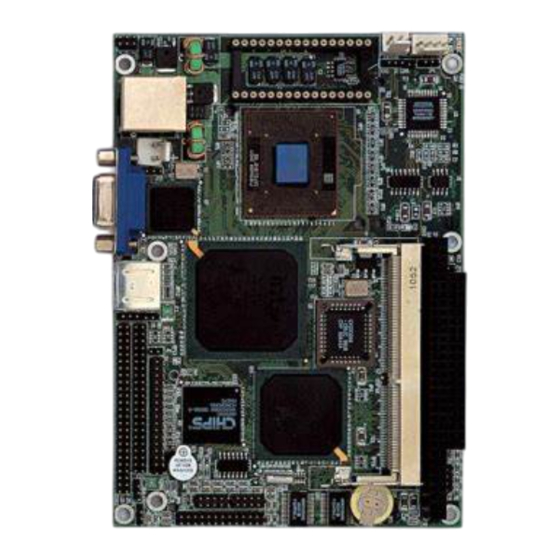
Page 11: Hs-2601'S Layout
2.3 HS-2601’s Layout... -
Page 12: Quick Listing Of Jumpers
2.4 Quick Listing of Jumpers — FAN Voltage Select — CPU Clock Select — Reset — LCD Voltage Select 2.5 Quick Listing of Connectors CN1: LAN Connector CN2: IR Connector CN3: 2-pin 5V Power In CN4: FAN Connector CN5: CRT Connector CN6: 4-pin EXT Power In CN7: Keyboard/Mouse 6-pin Header CN8: PS/2 6-pin Mini Din Keyboard/Mouse... -
Page 13: Jumper Setting Description
2.6 Jumper Setting Description A jumper pin-set is ON as a shorted circuit with a plastic cap inserted over two pins. A jumper pin-set is OFF as a open circuit with a plastic cap inserted over one or no pin(s) between pins. The below figure 2.2 shows the examples of different jumper pin-set setting as ON or OFF in this manual. -
Page 14: Setting The Bus-Clock Frequency
Bus-Clock Frequency *66MHz 100MHz 2.8 System Memory DRAM The HS-2601 provides a single size SDRAM memory by one piece SODIMM socket request the access time should meet PC-100 standard. The maximum capacity of the on board memory is 256MB. 2.9 Setting the Flat Panel Voltage... -
Page 15: Connection
This chapter gives all necessary information of the peripheral's connections, switches and indicators. 3.1 Power and FAN Connectors The HS-2601 provides one 2-pin DC-Power connector as following CN3 pin information. And also provides 4-pin EXT Power connector as following CN6 pin information. FAN Connector as following CN4 pin information. -
Page 16: Reset Button
Ground External Reset 3.3 Flash Disk HS-2601 also offer Flash Disk function. Capacity from 8MB to 64MB. HS-2601’s standard is equip with 16MB Flash Disk. But, Boser can up grate the Flash Disk capacity base on customer’s request. Boser’s Flash Disk is using IDE interface as IDE HDD,... -
Page 17: Pci E-Ide Drive Connector
3.4 PCI E-IDE Drive Connector One standard 44-pin header daisy-chain driver connector provides as CN11 with following pin assignment. Total two IDE (Integrated Device Electronics) drivers may connect. CN11: IDE Interface Connector PIN NO. DESCRIPTION PIN NO. DESCRIPTION RESET GROUND DATA 7 DATA 8 DATA 6... -
Page 18: Parallel Port Connector
3.5Parallel Port Connector A standard 26-pin flat cable driver connector provides as CN16 with following pin assignment for connection to parallel printer. CN16: Parallel Port Connector PIN NO. Description PIN NO. Description STROBE DATA 0 DATA 1 DATA 2 DATA 3 DATA 4 DATA 5 DATA 6... -
Page 19: The Floppy Disk Drive Connector
3.6 The Floppy Disk Drive Connector A standard 34-pin header daisy-chain driver connector provides as CN12 with following pin assignment. Total two FDD drivers may connect. CN12 : FDD CONNECTOR PIN NO. DESCRIPTION PIN NO. DESCRIPTION GROUND REDUCE WRITE GROUND GROUND DISK SELECT 1 GROUND... -
Page 20: Serial Ports Connectors
3.7 Serial Ports Connectors The HS-2601 offers two high speeds NS16C550 compatible UART with Read/Receive 16 byte FIFO serial ports with two internal 10-pin header. CN15/17 : Serial Port 10-pin Header (COM2/COM1) PIN NO. Description PIN NO. Description... -
Page 21: Keyboard/Mouse Connectors
3.8 Keyboard/Mouse Connectors The HS-2601 offers two possibilities for Keyboard/Mouse connections to external PS/2 type at CN8, or an internal 6-pin header at CN7. CN7: 6-pin Header Keyboard/Mouse Connector PIN NO. Description KEYBOARD CLOCK MOUSE DATA GROUND KEYBOARD DATA MOUSE CLOCK CN8 : 6-pin Mini Din Keyboard/Mouse Connector PIN NO. -
Page 22: Vga Crt And Lcd Connectors
3.9 VGA CRT and LCD Connectors The HS-2601 provides two possible connectives of VGA connections. One standard DB-15 external VGA connector as following CN5 pin information. Another internal 50-pin header for LCD Panel connection as following CN13 pin information. CN13 : 50-pin Internal LCD Panel Connector PIN NO. - Page 23 Flat Panel Display Interface (continued) Mono Mono Color Color Color Color Color Color Color Color Color Color HS-2601 STN- STN- STN- STN- STN-D STN-D 9/12/16 18/24 36-bit 18/24 8-bit 16-bit 8-bit 16-bit 8-bit 8-bit 16-bit 24-bit Name (4bP) (4bP) (4bP) (4bP) SHFCLK: Pixel clock .Shift Clock...
-
Page 24: Ir Connector
GROUND GROUND GROUND GROUND GROUND DDC DATA HSYNC VSYNC DDC CLK 3.10 IR Connector The HS-2601 provides a 5-pin internal IR communication connector as following CN2 pin information. CN2 : 5-pin IR Connector PIN NO. Description FIRRX IRRX GROUND IRTX... -
Page 25: Usb Ports Connector
3.11 USB Ports Connector The HS-2601 provides two internal 8-pin USB ports connectors. Please refer to the following detail pin information. CN14: 8-pin Header USB Connector PIN NO. CN14 PIN NO. CN14 BD0- BD1- BD0+ BD1+ GROUND GROUND 3.12 LAN Interface Connector The HS-2601 provides one external RJ-45 100 based LAN interface connector. -
Page 26: Mini Pci Connector
3.13 Mini PCI Connector HS-2601 support Mini PCI interface which is very popular in Notebook Computer’s expansion like Modem, Video, LAN and etc. Mini PCI’s definition is as following. U5 : Mini PCI Connector Pin Information PIN NO. PIN NO. -
Page 27: Pc/104 Bus Connection
SYS_AUDIO_OUT SYS_AUDIO_IN 3.14PC/104 Bus Connection The HS-2601’s PC/104 expansion bus provides you to connect all kind of PC/104 modules. The PC/104 bus has been already become the industrial embedded 16bit PC standard bus. You can easily install over thousands type of PC/104 modules from hundreds of venders in the world. - Page 28 CN9&CN10 : PC/104 Expansion Bus (CN10 = 64-pin female connector; CN9 = 40-pin female connector.) CN10 CN10 Row A Row B Row D Row C 1 IOCHECK* 33 0V 1 0V 21 0V 2 SD7 34 RESETDRV 2 MEMCS16* 22 SBHE* 3 SD6 35 +5V 3 IOSC16*...
-
Page 29: Award Bios Setup
Chapter-4 AWARD BIOS Setup The HS-2601 uses the Award PCI/ISA BIOS for the system configuration. The Award BIOS setup program is designed to provide the maximum flexibility in configuring the system by offering various options which could be selected for end-user requirements. -
Page 30: Main Menu
4.1 Main Menu Once you enter the Award BIOS CMOS Setup Utility, the Main Menu will appear on the screen. The Main Menu allows you to select from several setup functions and two exit choices. Use the arrow keys to select among the items and press <Enter> to enter the sub-menu. -
Page 31: Standard Cmos Setup
4.2 Standard CMOS Setup The Standard Setup is used for the basic hardware system configuration. The main function is for Data/Time and Floppy/Hard Disk Drive settings. Please refer to the following screen for the setup. When the IDE hard disk drive you are using is larger than 528MB, please set the HDD mode to LBA mode. -
Page 32: Bios Features Setup
4.3 BIOS Features Setup This section allows you to configure your system for the basic operation. You have the opportunity to select the system’s default speed, boot-up sequence, keyboard operation, shadowing and security. Virus Warning : Disabled Video BIOS Shadow : Enabled CPU Internal Cache : Enabled... -
Page 33: Chipset Features Setup
4.4 Chipset Features Setup This section allows you to configure the system based on the specific features of the installed chipset. This chipset manages bus speeds and the access to the system memory resources, such as DRAM and the external cache. It also coordinates the communications between the conventional ISA and PCI buses. -
Page 34: Integrated Peripherals
4.5 Integrated Peripherals The IDE hard drive controllers can support up to two separate hard drives. These drives have a master/slave relationship which is determined by the cabling configuration used to attach them to the controller. Your system supports two IDE controllers--a primary and a secondary--so you can install up to four separate hard disks. - Page 35 Panel# Panel Type 1024*768 Dual Scan STN Color Panel 128*1024 TFT Color Panel 640*480 Dual Scan STN Color Panel 800*600 Dual Scan STN Color Panel 640*480 Sharp TFT Color Panel 640*480 18-bit TFT Color Panel 1024*768 TFT Color Panel 800*600 TFT Color Panel 800*600 TFT Color Panel (Large BIOS ONLY) 800*600 TFT Color Panel (Large BIOS ONLY) 800*600 Dual Scan STN Color Panel (Large BIOS ONLY)
-
Page 36: Power Management Setup
4.6 Power Management Setup The Power Management Setup allows user to configure the system for saving energy in a most effective way while operating in a manner consistent with his own style of computer use. ACPI function Disabled Power Management User Define ** Reload Global Timer Events ** PM Control by APM... -
Page 37: Pnp/Pci Configuration Setup
4.7 PnP/PCI Configuration Setup In this section, the PnP/PCI configuration setup allows you to configure the ISA and PCI devices installed in your system by manually or auto. PnP OS Installed Assign IRQ For VGA : Enabled Resources Controlled by Auto Slot 1 Use IRQ No. -
Page 38: Software Utilities
Chapter-5 Software Utilities This chapter the detailed information of VGA and LAN function. How to install the configuration is also included. Section include: VGA DRIVER INSTALLATION NETWORK DRIVER INSTALLATION... -
Page 39: Vga Driver Install For Win95&98
5.1 VGA DRIVER INSTALL FOR WIN95&98 1. Click Start, then Setting, then Control Panel. 2. Start the Display applet program. 3. Select the setting page, push the Advanced properties button. 4. Push the change button in the adapter area. 5. Continue to click “Next”. Select Display a list of all drivers in a specific location, so you can select the drivers you want. -
Page 42: Vga Driver Install For Win Nt4.0
5.2 VGA DRIVER INSTALL FOR WIN NT4.0 1. Click the Start button, then go to Settings and click on Control Panel. 2. Click on Display icon to start the Display Properties window. 3. Click on the Settings tab, and then click on Display Type. 4. -
Page 46: Network Driver Install For Win98&95
5.3 NETWORK DRIVER INSTALL FOR WIN98&95 Win98 Windows 98 will detect the network driver automatically. Win95 1. Click Start, then Settings, in the “Setting” select Control panel. 2. Start the network applet program. 3. In the Network window, click Add. 4. -
Page 49: Network Driver Install For Win Nt4.0
5.4 NETWORK DRIVER INSTALL FOR WIN NT4.0 1. Click the Start button, then go to Settings and click on Control Panel. 2. Click on the Network icon to start the Network window. 3. Click on the Adapters tab, and then click on Add. 4.
Need help?
Do you have a question about the HS-2601 and is the answer not in the manual?
Questions and answers