Table of Contents
Advertisement
Quick Links
Advertisement
Table of Contents

Subscribe to Our Youtube Channel
Related Manuals for Boser HS-6252


Summary of Contents for Boser HS-6252
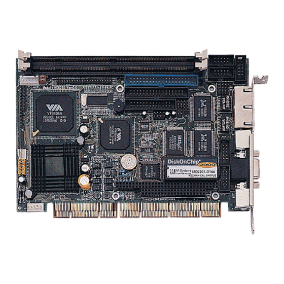
- Page 1 HS-6252 VIA C3 800MHz Embedded CPU Industrial Single Board Computer •Half Size•All-in-One•CRT•133MHz FSB• •ATA/33/66/100•Dual LAN•Audio• •RS-232/422/485•4COM•PC/104• •IrDA•USB•DOC•WDT•H/W Monitor• •PCI-ISA Bus Industrial Single Board computer•...
- Page 2 Copyright Disclaimers The accuracy of contents in this manual has passed thorough checking and review before publishing. BOSER Technology Co., Ltd., the manufacturer and publisher, is not liable for any infringements of patents or other rights resulting from its use. The...
-
Page 3: Table Of Contents
Table of Contents Chapter 1 General Description ........1 1.1 Major Features ............... 2 1.2 Specifications ................ 3 1.3 Board Dimensions..............4 Chapter 2 Unpacking ..........5 2.1 Opening the Delivery Package..........5 2.2 Inspection................5 Chapter 3 Hardware Installation ......7 3.1 Before Installation ..............7 3.2 Board Layout ................. - Page 4 Chapter 4 AMI BIOS Setup ........31 4.1 Starting Setup ..............31 4.2 Using Setup................32 4.3 Main Menu ................33 4.4 Standard CMOS Setup ............35 4.5 Advanced CMOS Setup ............38 4.6 Advanced Chipset Setup ............ 41 4.7 Power Management Setup ..........42 4.8 PCI / Plug and Play Setup...........
- Page 5 Fasten the ALLIGATOR clip of the strap to the end of the shielded wire lead from a grounded object. Please wear and connect the strap before handle the HS-6252 to ensure harmlessly discharge any static electricity through the strap.
- Page 6 This page intentionally left blank.
-
Page 7: Chapter 1 General Description
I/O with CRT, Dual LAN, and 4 COM ports interface. Its onboard ATA/33/66/100 to IDE drive interface architecture allows the HS-6252 to support data transfers of 33, 66 or 100MB/sec. to each IDE drive connection. Designed with the VIA VT8601 core logic chipset, the board supports VIA C3 800MHz Embedded CPU. -
Page 8: Major Features
RJ-45 connectors for 10/100 Based Ethernet use. To ensure the reliability in an unmanned or standalone system, the Watchdog Timer (WDT) onboard HS-6252 is designed with pure hardware that does not need the arithmetical functions of a real-time clock chip. If any program causes unexpected halts to the system, the onboard Watchdog Timer (WDT) will automatically reset the CPU or generate an interrupt to resolve such condition. -
Page 9: Specifications
Specifications CPU: VIA C3 800MHz embedded CPU Bus Interface: PCI-ISA Bus Memory: Two DIMM sockets supporting up to 1GB Chipset: VIA VT8601/VT82C686B I/O Chipset: SMC 37C669, VIA VT82C686B VGA: VIA VT8601 integrated Trident 3D supporting AGP Bus IDE: Two IDE disk drives supporting ATA/33/66/100 and with transfer rates up to 33/66/100MB/sec. -
Page 10: Board Dimensions
Board Dimensions... -
Page 11: Unpacking
Chapter 2 Unpacking Opening the Delivery Package The HS-6252 is packed in an anti-static bag. The board has components that are easily damaged by static electricity. Do not remove the anti-static wrapping until proper precautions have been taken. Safety Instructions in front of this manual describe anti-static precautions and procedures. - Page 12 It is recommended that you keep all the parts of the delivery package intact and store them in a safe/dry place for any unforeseen event requiring the return shipment of the product. In case you discover any missing and/or damaged items from the list of items, please contact your dealer immediately.
-
Page 13: Chapter 3 Hardware Installation
Chapter 3 Hardware Installation This chapter provides the information on how to install the hardware using the HS-6252. This chapter also contains information related to jumper settings of switch, watchdog timer, and the DiskOnChip address selection etc. Before Installation After confirming your package contents, you are now ready to install your hardware. -
Page 14: Board Layout
Board Layout... -
Page 15: Jumper List
Jumper List Jumper Default Setting Setting CPU Clock Frequency: 800MHz Short JP4(1-4) DOC Address Select: D000 Short 1-2 JP4(5-10) WDT Timer Select: 1sec. Short 5-6, 7-8, 9-10 Clear CMOS: Normal Operation Short 1-2 WDT Active Type Setting: Reset Short 2-3 RS-422/485 Transceiver Enabled/Disabled Open 1-2, 3-4, 5-6 Select: Disabled... -
Page 16: Configuring The Cpu
DOC in your system, please set both at different memory address mapping to avoid the mapping area conflicts. Failing to do so will not make the HS-6252 and the additional memory device function properly. - Page 17 3. Once you have figured out where the pin 1 locations are on both chip and socket, align the module’s pins on an upright angle against the socket. Using both thumbs, gently press the module into the socket until all the pins are secured to their designations.
-
Page 18: Vga Controller
VGA Controller The HS-6252 has an onboard VGA controller, provides 8MB shared memory. The HS-6252 provides one connection method of a VGA device. VGA1 offers a single standard CRT connector (DB15). VGA1: 15-pin CRT Connector (DB15) Description Description Green Blue... -
Page 19: Pci E-Ide Drive Connector
PCI E-IDE Drive Connector IDE1 is a standard 40-pin connector daisy-chain driver connector serves the PCI E-IDE drive provisions onboard the HS-6252. A maximum of two ATA/33/66/100 IDE drives can connect to the HS-6252 via IDE1. IDE1: IDE Connector Description... -
Page 20: Floppy Disk Drive Connector
3.10 Floppy Disk Drive Connector The HS-6252 uses a standard 34-pin header connector, FDD1, for floppy disk drive connection. A total of two FDD drives may be connected to FDD1 at any given time. FDD1: FDD Connector Description Description DRVDEN0... -
Page 21: Serial Port Connectors
3.11 Serial Port Connectors The HS-6252 offers two NS16C550 compatible UARTs with Read/Receive 16-byte FIFO serial ports and two internal 10-pin headers. CN9, CN8, CN5 and CN6: COM1/COM2/COM3/COM4 Connectors (5x2 Header) Description Description CN10: RS-422/485 Connector (5x2 Header) Description Description... -
Page 22: Parallel Connector
Auto Form Feed ERROR# Initialize Printer Select LN# 3.13 Ethernet Connector The HS-6252 provides one external dual RJ-45 10/100 Based LAN interface connector. Please refer to the following for its pin information. LAN1A & 1B: Dual RJ-45 Connector Description No Use... -
Page 23: Irda Connector
IrDA device. IR1: IrDA Connector Description IRRX IRTX 3.15 USB Connector The HS-6252 provides two 8-pin connectors, at locations USB1 and USB2, for four USB connections to the HS-6252. USB1 and USB2: USB Connector Description Description BD0- / BD2- BD1- / BD3-... -
Page 24: Power, Atx Power Controller And Fan Connectors
3.17 Power Supply, ATX Power Controller and Fan Connectors HS-6252 provides one 5-pin power control connector at CN2. If you need to use ATX power supply, power supply connections to both CN2 and CN11 are must. CN2: 5-pin Power Connector... - Page 25 2-pin 5V power in cable (not attached in cable package) 3.17.1 HS-6252 Connect with ATX Power Supply and BOSER Backplane (ATX function) 1. HS-6252 CN2 connects to 5-pin connector (Backplane). ATX power supply connect to backplane ATX connector. 2. Power switch cable (cable1) connects to JP1(10-12).
- Page 26 3.17.2 HS-6252 Connect with ATX Power Supply and BOSER Backplane (AT power function) 1. 20-pin ATX power connector (Backplane) connects to ATX power supply. 2. Use Cable1 connect to pin-4 and pin-5 of 5-pin connector on BOSER’s backplane.
- Page 27 3.17.3 HS-6252 Connect with ATX Power Supply (Without Backplane) 1. Use Cable3 connect CN2 & CN11 with ATX power supply. 2. Cable1 connect to JP1(10-12). 3.17.4 HS-6252 Connect with AT Power Supply and BOSER Backplane 1. Connects P8P9 connector to AT power supply.
-
Page 28: Keyboard Connectors
1. Connects CN11 to AT power supply. (Through cable4) 3.18 Keyboard Connectors The HS-6252 offers two possibilities for keyboard connections. The connections are via KB1 for an external PS/2 type keyboard or via CN1 for an internal 5-pin cable converter to an AT keyboard. -
Page 29: Ps/2 Mouse Connector
3.19 PS/2 Mouse Connector MS1 is a 6-pin mini DIN connector for connections to an external PS/2 mouse connector. CN7 is an internal 4-pin header for cable converter to PS/2 mouse. MS1: PS/2 6-pin Mini Din Mouse Connector Description Mouse Data MS Clock MS Data Mouse Clock... -
Page 30: System Front Panel Connectors
3.20 System Front Panel Connectors The HS-6252 has one LED at location JP1(2-4) that indicates the power-on status. This visual feature of the IDE LED may also be connected to an external IDE LED via connector JP1(13-15). JP1: System Front Panel Connector PIN Description PIN Description 330Ω... -
Page 31: Watchdog Timer
3.22 Watchdog Timer Enable, Refresh There are three access cycles of Watch-Dog Timer as and Disable are the three access cycles of Watchdog Timer. The Enable cycle proceeds via READ PORT 443H whereas the Disable cycle proceeds via READ PORT 045H. A continued Enable cycle after a first Enable cycle means Refresh. - Page 32 443H I/O Read The Enable cycle 443H I/O Read The Refresh cycle 045H I/O Read The Disable cycle The following sample program shows how to Enable, Disable and Refresh the Watchdog Timer: WDT_EN_RF 0433H WDT_DIS 0045H WT_Enable PUSH ; keep AX DX PUSH DX,WDT_EN_RF ;...
-
Page 33: Pc/104 Connectors
3.23 PC/104 Connectors The PC/104 expansion bus offers provisions to connect all types of PC/104 modules. With the PC/104 bus being known as the new generation of industrial embedded 16-bit PC standard bus, thousands of PC/104 modules from multiple venders can be easily installed onboard. - Page 34 PC1: 64-pin PC/104 Expansion Slot Description PIN Description Connector diagram rotated 90 degrees IOCHECK* clockwise from RESETDRV original position IRQ9 DRQ2 -12V NOW* +12V IOCHRDY SMEMW* SA19 SMEMR* SA18 IOW* SA17 IOR* SA16 DACK3* SA15 DRQ3 SA14 DACK1* SA13 DRQ1 SA12 REFRESH* SA11...
-
Page 35: Audio Connectors
3.24 Audio Connectors The HS-6252 has an onboard AC97 3D audio interface. The following tables list the pin assignments of the CD-ROM Analog Input, the Line In and the MIC In / Line Out connectors. CD1: CD-ROM Line In Connector... - Page 36 This page intentionally left blank.
-
Page 37: Chapter 4 Ami Bios Setup
Chapter 4 AMI BIOS Setup The HS-6252 uses AMI BIOS for the system configuration. The AMI BIOS setup program is designed to provide the maximum flexibility in configuring the system by offering various options that could be selected for end-user requirements. This chapter is written to assist you in the proper usage of these features. -
Page 38: Using Setup
Using Setup In general, you use the arrow keys to highlight items, press <Enter> to select, use the <PageUp> and <PageDown> keys to change entries, press <F1> for help and press <Esc> to quit. The following table provides more detail about how to navigate in the Setup program using the keyboard. -
Page 39: Main Menu
Main Menu Once you enter the AMI BIOS CMOS Setup Utility, the Main Menu will appear on the screen. The Main Menu allows you to select from several setup functions and two exit choices. Use the arrow keys to select among the items and press <Enter>... - Page 40 Hardware Monitor Setup This menu contains the system’s auto-detect functions for CPU Vcore, CPU voltage, and CPU temperature. Auto-Detect Hard Disks Automatically detect and configure hard disk parameters. The AMI BIOS includes this ability in the event you are uncertain of your hard disk’s parameters.
-
Page 41: Standard Cmos Setup
Standard CMOS Setup The Standard Setup is used for the basic hardware system configuration. The main function is for Data/Time and Floppy/Hard Disk Drive settings. Please refer to the following screen for the setup. When the IDE hard disk drive you are using is larger than 528MB, you must set the HDD mode to LBA mode. - Page 42 Floppy A / B: The category identifies the types of floppy disk drive A or drive B that have been installed in the computer. None No floppy drive installed 360K, 5.25 in 5-1/4 inch PC-type standard drive; 360 kilobyte capacity 1.2M, 5.25 in 5-1/4 inch AT-type high-density drive;...
- Page 43 Boot Sector Virus Protection: If set to Enabled, this category will flash on the screen when there is any attempt to write to the boot sector or partition table of the hard disk drive. The system will halt and an error message will appear.
-
Page 44: Advanced Cmos Setup
Advanced CMOS Setup This section allows you to configure your system for the basic operation. You have the opportunity to select the system’s default speed, boot-up sequence, keyboard operation, shadowing and security. AMIBIOS SETUP – STANDARD CMOS SETUP (C)2001 American Megatrends, Inc. All Rights Reserved Quick Boot Enabled Available Options:... - Page 45 2nd Boot Device: This option sets the type of SECOND device from where the BIOS will seek to boot from, if and when the 1st Boot Device fails after AMIBIOS POST completes. The available settings are Disabled, IDE-0, IDE-1, IDE-2, IDE-3, Floppy, ARMD-FDD, ARMD-HDD, CDROM, and SCSI.
- Page 46 Password Check: This option enables the password check option every time the system boots or the end user runs Setup. If set as Always, a user password prompt appears every time the computer is tuned on. If setup is chosen, the password prompt appears if BIOS is executed.
-
Page 47: Advanced Chipset Setup
Advanced Chipset Setup This section allows you to configure the system based on the specific features of the installed chipset. This chipset manages bus speeds and the access to the system memory resources, such as DRAM and the external cache. It also coordinates the communications between the conventional ISA and PCI buses. -
Page 48: Power Management Setup
Power Management Setup The Power Management Setup allows user to configure the system for saving energy in a most effective way while operating in a manner consistent with his own style of computer use. AMIBIOS SETUP – POWER MANAGEMENT SETUP (C)2001 American Megatrends, Inc. - Page 49 ACPI Aware O/S: This item is the Advanced Configuration and Power Interface (ACPI) function switch. The available options are Yes, and No. ACPI Standby State: This item serves as the switch setting of STR (S3) or POS (S1) function. Configuration options are S3/STR, and S1/POS. Power Management/APM: Set this option to Enabled to switch on the APM (Advanced Power Management).
-
Page 50: Pci / Plug And Play Setup
PCI / Plug and Play Setup This section describes configuring the PCI bus system. PCI, or Personal Computer Interconnect, is a system that allows I/O devices to operate at speeds nearing the speed the CPU itself uses when communicating with its own special components. This section covers some very technical items and it is strongly recommended that only experienced users should make any changes to the default settings. -
Page 51: Peripheral Setup
Peripheral Setup The IDE hard drive controllers can support up to two separate hard drives. These drives have a master/slave relationship that is determined by the cabling configuration used to attach them to the controller. Your system supports two IDE controllers--a primary and a secondary--so you can install up to four separate hard disks. - Page 52 OnBoard Parallel Port: This option specifies the base I/O port address of parallel port on the system board. The available settings are Disabled, 378h, 278h, and 3BCh. Parallel Port Mode: This option specifies the parallel port mode. The available settings are Normal, Bi-Dir, EPP, and ECP. Normal: The normal parallel port mode is used.
-
Page 53: Hardware Monitor Setup
4.10 Hardware Monitor Setup AMIBIOS SETUP – HARDWARE MONITOR SETUP (C)2001 American Megatrends, Inc. All Rights Reserved *** System Hardware Monitor *** Available Options: Chassis Intrusion Disabled Disabled TSENS1 Temperature Enabled CPU Fan Speed Reset Chassis Fan Speed Vcore + 2.500V +3.300V +5.000V +12.000V... -
Page 54: Auto-Detect Hard Disks
4.11 Auto-Detect Hard Disks This option detects the parameters of an IDE hard disk drive, and automatically enters them into the Standard CMOS Setup screen. Up to four IDE drives can be detected, with parameters for each appearing in sequence inside a box. To accept the displayed entries, press the “Y”... -
Page 55: Change Supervisor/User Password
4.12 Change Supervisor/User Password AMIBIOS HIFLEX SETUP UTILITY – VERSION 1.54 (C)2001 American Megatrends, Inc. All Rights Reserved Standard CMOS Setup Advanced CMOS Setup Advanced Chipset Setup Power Management Setup Enter new supervisor password: _ Change Supervisor Password Auto Configuration with Optimal Settings Auto Configuration with Fail Safe Settings Save Settings and Exit Exit Without Saving... -
Page 56: Auto Configuration With Optimal Settings
When a password has been enabled, you will be prompted to enter it every time you try to enter Setup. This prevents an unauthorized person from changing any part of your system configuration. Additionally, when a password is enabled, you can also require the BIOS to request a password every time your system is rebooted. -
Page 57: Auto Configuration With Fail Safe Settings
4.14 Auto Configuration with Fail Safe Settings When you press <Enter> on this item you get a confirmation dialog box with a message similar to the figure below. This option allows you to load/restore the default values to your system configuration, optimizing and enabling all high performance features. -
Page 58: Save Settings And Exit
4.15 Save Settings and Exit Pressing <Enter> on this item asks for confirmation: AMIBIOS HIFLEX SETUP UTILITY – VERSION 1.54 (C)2001 American Megatrends, Inc. All Rights Reserved Standard CMOS Setup Advanced CMOS Setup Advanced Chipset Setup Power Management Setup Save current settings and exit (Y/N) ? Y Change Supervisor Password Auto Configuration with Optimal Settings Auto Configuration with Fail Safe Settings... -
Page 59: Exit Without Saving
4.16 Exit Without Saving Pressing <Enter> on this item asks for confirmation: Quit without saving (Y/N)? Y This allows you to exit Setup without storing in CMOS any change. The previous selections remain in effect. This exits the Setup utility and restarts your computer. - Page 60 This page intentionally left blank.
-
Page 61: Chapter 5 Software Utilities
Chapter 5 Software Utilities This chapter contains the detailed information of IDE, VGA, Audio and LAN driver installation procedures. IDE and Audio Driver Installation The utility disk that came with the delivery package contains an auto-run program that invokes the installation programs for the IDE, VGA and Audio drivers. - Page 62 Press “VIA 4 IN 1” and to go Setup. Once the Welcome screen appears on the screen, make sure to close any applications running and then click on the Next button. When the Readme window pops on the screen, you may read the whole document including the license agreement or just press Yes to skip through and continue installation.
- Page 63 The 4 in 1 Setup dialog is now displayed. Select on Normally Install and then click on Next. The next window lists all components detected in your system and asks you to select the ones requiring drivers. Tick on all items then proceed by clicking on the Next button below the screen.
- Page 64 The program starts to install the ATAPI driver when you click the Next button on the screen below. When the ATAPI driver is completely installed. The utility then displays your DMA mode status and allows you to enable it. Tick on the box and press on the Next button to continue.
- Page 65 The following screen then gives you the choice of installing the AGP driver in standard o turbo mode. Select on the Standard Mode and then click on Next to proceed. 10. Installation of the AGP driver is now complete. Once the screen below appears, select on restarting your computer to activate all drivers/settings completed.
- Page 66 5.1.2 VIA IDE Tool Installation With the Utility CD Disk still in your CD ROM drive, open the File Manager and then select the CD-ROM drive. As soon as the system reads the disk, the following screen will appear on your display.
- Page 67 The Select Components dialog box is now displayed. Select on Install and then click on Next. Choose the folder to where the program will install the driver. Select the default folder (C:\Program Files\IDETOOL) and then click on Next to proceed.
- Page 68 The program will now create an icon for the IDETOOL. Simply press Next to continue with the installation. The program now installs and transfers the files to your system. After it finishes, you will be prompted to restart your system. We recommend you to reboot your computer to allow the new settings to take effect.
- Page 69 Once the system enters the main Windows screen, it will display a new icon along the right hand task bar. This icon represents the IDE Tool quick launch program. Double-clicking on this new task bar icon will launch the IDE Tool’s Drive Feature dialog box, as shown below.
- Page 70 The Drive Feature dialog box has 2 columns of information. The left column lets you to view the hardware installed on your system. When you select any hardware, the right column displays the device’s information and specifications. You may also update the settings of your devices from the right column. 10.
- Page 71 5.1.3 Audio Driver Installation With the Utility CD Disk still in your CD ROM drive, open the File Manager and then select the CD-ROM drive. As soon as the system reads the disk, the VGA Menu screen below will appear on your display.
- Page 72 The Select Components dialog box is now displayed. Select on Install driver and then click on Next. The program will now require the Windows installation disk for proper hardware installation. Insert the CD and then click on Next.
- Page 73 When the display below appears on your screen, Setup is already installing and copying the related files onto your hard drive. Click on the Next button to proceed. After the audio driver installation finishes, select the Finish button to complete the installation process.
-
Page 74: Lan Driver Installation For Win95 & Win98
LAN Driver Installation for WIN95 & WIN98 1. With the Utility CD Disk still in your CD ROM drive, right click on My Computer icon from the Windows menu. Select on System Properties and then proceed to the Device Manager from the main menu. - Page 75 3. The PCI Ethernet Controller Properties screen then appears, allowing you to re-install the driver. Select Driver from the main menu to proceed.
- Page 76 4. The window then displays the current status of your LAN driver. Press on Update Driver button to continue. 5. The program will then launch the Update Device Driver Wizard window that will install your device driver. Click on the Next button to proceed to the next step.
- Page 77 7. The Update Device Driver Wizard will then ask you to specify, by ticking, the path of the new driver. Tick on the open boxes where you require the program to search for the device driver then click on the Browse button to manually specify the path. 8.
- Page 78 9. Once the program returns to the Add New Hardware Wizard screen, your specified location will appear. Press on the Next button to continue. 10. Once the program detects the device driver (*.inf) file from your specified location, it will automatically copy the files into your hard drive.
- Page 79 12. The program then copies the necessary files from your Windows installation disk to complete the driver setup process. Once the driver is completely installed, the following message appears on your display. Click on the Finish button to proceed. 13. Restart your computer to make the new system settings take effect.
-
Page 80: Lan Driver Installation For Win Nt4.0
LAN Driver Installation for WIN NT4.0 With the Utility CD Disk still in your CD ROM drive, right click on Network Neighborhood icon from the Windows menu. Select on Properties. The system automatically detects the absence of Windows NT Networking. Click on the Yes button to start installation. - Page 81 Tick on the “Wired to Network” once the following screen appears. Click on the Next to proceed. Click on the Start Search button for the program to locate the Network Adapter.
- Page 82 Once setup finishes the search, it will list a number of adapters for you to choose from. Press on the Have Disk button to assign the driver path location. Setup now asks you for the location of the driver. When you have entered the new driver path, press on the OK button to continue.
- Page 83 When Setup finds the information it needs about the new driver, it will display the device it found on the following screen. Press on the OK button to accept and proceed. Setup then returns to Network Setup Wizard screen and displays your new Network Adapter.
- Page 84 The Network Setup Wizard then allows you to set the Network Protocols on your network. Select the appropriate protocol and then click on Next to continue. 10. Before Setup starts installing the components found and the settings you made, it will give you the option to proceed or go back for changes from the following screen.
- Page 85 11. Windows NT Setup will then need to copy files necessary to update the system information. Specify the path then press Continue. 12. Once it finishes copying the files, Setup will now allow you to choose the Duplex Mode of your LAN controller. Press on the Continue button after making your selection.
- Page 86 13. When Setup asks if you wish to change the TCP/IP settings of your system, select the appropriately. The default choice is No. 14. Setup then starts the Networking installation and copies the files.
- Page 87 15. When Setup finishes copying, the TCP/IP properties of your system will then pop up on your screen like the one shown below. Make the necessary changes then click on OK to continue. 16. When the screen below appears, click on Next to continue.
- Page 88 17. Setup then prompts you that it is ready to start the network. You may complete the installation thereafter. Click on Next to continue. 18. Assign the workgroup or domain setting of your computer. Click on Next to continue.
- Page 89 19. Restart your computer once the screen below appears. Click on Finish to continue. 20. Click on the Yes button to restart your computer. The LAN driver installation for WIN NT4.0 is now complete.
- Page 90 This page intentionally left blank.
Need help?
Do you have a question about the HS-6252 and is the answer not in the manual?
Questions and answers