
Related Manuals for Boser HS-7280


Summary of Contents for Boser HS-7280
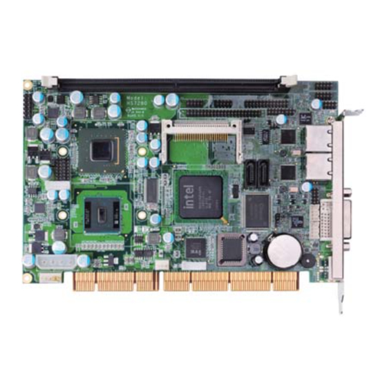
- Page 1 HS-7280 Intel® Atom™ N270 processor PCI-ISA Bus Single Board Computer •CompactFlash•DVI-I/CRT/LVDS• •Dual Gigabit Ethernet•Audio•GPIO• •SATA•RS-232/422/485• •4 COM•4 USB2.0•WDT•H/W Monitor•...
- Page 2 Unauthorized reproduction, transmission, translation, and storage of any form and means (i.e., electronic, mechanical, photocopying, recording) of this document, in whole or partly, is prohibited, unless granted permission by BOSER Technology Co., Ltd. reserves the right to change or improve the contents of BOSER Technology Co., Ltd.
-
Page 3: Table Of Contents
Table of Contents Chapter 1 General Description ........1 1.1 Major Features ............... 2 1.2 Specifications ................ 2 1.3 Board Dimensions ..............4 Chapter 2 Unpacking ..........5 2.1 Opening the Delivery Package ..........5 2.2 Inspection ................5 Chapter 3 Hardware Installation ...... - Page 4 Chapter 4 Award BIOS Setup ......... 27 4.1 Starting Setup ..............27 4.2 Using Setup ................. 28 4.3 Main Menu ................29 4.4 Standard CMOS Features ........... 30 4.5 Advanced BIOS Features ........... 31 4.6 Advanced Chipset Features ..........32 4.7 Integrated Peripherals ............
- Page 5 Declaration of Conformity -- CE Mark BOSER Technology hereby acknowledges that compliance testing in accordance with applicable standards of the EU’s EMC Directive, 89/336/EEC, was successfully completed on a sample of the equipment identified below: Equipment Class: Information Technology Equipment...
- Page 6 Fasten the ALLIGATOR clip of the strap to the end of the shielded wire lead from a grounded object. Please wear and connect the strap before handle the HS-7280 to ensure harmlessly discharge any static electricity through the strap.
-
Page 7: Chapter 1 General Description
The HS-7280 is an Intel® 945GSE/ICH7-M chipset-based board designed, the board supports Intel® Atom™ N270 processor 1.6GHz. The HS-7280 is an ideal all-in-one embedded engine board. Additional features include an enhanced I/O with CF, CRT/DVI-I/LVDS, dual Gigabit Ethernet, audio, SATA, 4 COM, and 4 USB2.0 interfaces. -
Page 8: Major Features
And two RJ-45 connectors for 10/100/1000 Based Ethernet uses. To ensure the reliability in an unmanned or standalone system watchdog timer (WDT) onboard HS-7280 is designed with , the software that does not need the arithmetical functions of a real-time clock chip. - Page 9 GPIO: 8-bit general purpose input/output port Watchdog Timer: Software programmable time-out intervals from 1~255 sec. or 1~255 min. H/W Status Monitor: Monitoring temperatures, voltages, and cooling fan status Power Function AT/ATX power mode support Operating Temperature: 0~+60 degrees C Operating Humidity: 0~95%, non-condensing Board Size (L x W): 186 x 122 mm...
-
Page 10: Board Dimensions
Ethernet Chipset: Dual RealTek RTL8111C Gigabit Ethernet Ethernet Interface: 2 x RJ-45 Board Dimensions... -
Page 11: Chapter 2 Unpacking
Chapter 2 Unpacking Opening the Delivery Package The HS-7280 is packed in an anti-static bag. The board has components that are easily damaged by static electricity. Do not remove the anti-static wrapping until proper precautions have been taken. Safety Instructions in front of this manual describe anti-static precautions and procedures. - Page 12 Cables Package Description QTY. SATA device cable SPK 8-pin(2.0-pitch) phone jack x 2 2 RS-232 cable (2.0-pitch) 1-to-2 USB cable w/bracket ATX Power Ctrl cable 1-to-2 Mini DIN cable It is recommended that you keep all the parts of the delivery package intact and store them in a safe/dry place for any unforeseen event requiring the return shipment of the product.
-
Page 13: Chapter 3 Hardware Installation
Chapter 3 Hardware Installation This chapter provides the information on how to install the hardware using the HS-7280. This chapter also contains information related to jumper settings of switch, and watchdog timer selection etc. Before Installation After confirming your package contents, you are now ready to install your hardware. -
Page 14: Board Layout
Board Layout Jumper List Jumper Default Setting Setting Page Panel Voltage Select: +3.3V Short 2-3 CF Use Master/Slave Select: Slave Open COM2 Use RS-232 or RS-422/485 Select: Open RS-232 AT/ATX Power Mode Select: ATX Open Clear CMOS: Normal Operation Open Onboard LAN1 Enabled/Disabled Select: JP13 Open... -
Page 15: Connector List
The HS-7280 embedded with Intel® Atom™ N270 processor 1.6GHz. User don’t need to adjust the frequently and check speed of CPU. System Memory The HS-7280 provides one 240-pin DIMM socket at location CN5. It supports DDR2 533MHz up to 2GB SDRAM. -
Page 16: Vga Controller
VGA Controller The HS-7280 provides three connection methods of a VGA device. CN18 is a 15-pin CRT connector, and JP3/JP2 are the LVDS interface connectors onboard reserved for flat panel installation. HS-7280 also provides DVI-I at location CN19. CN18: 15-pin CRT Connector... - Page 17 If you want to use 36-bit dual channel LVDS panel, please use JP3 and JP2 combined. The HS-7280 has an onboard jumper that selects the working voltage of the flat panel connected to the system. Jumper JP1 offers two voltage settings for the user.
-
Page 18: Ide Drive Connector
IDE Drive Connector CN7 is a 2.0-pitch 44-pin connector which support up to 2 ATA/33/66/100 IDE drives can be connected to the HS-7280 via CN7. CN7: IDE Connector Description Description Reset DATA7 DATA 8 DATA 6 DATA 9 DATA 5... -
Page 19: Serial Ata Connector
SATATXP SATATXN SATARXN SATARXP 3.10 Serial Port Connectors The HS-7280 offers 16C550 compatible UARTs with 16-byte Send/ Receive FIFO serial ports. JP4/JP5/JP12/JP11: COM1 ~ COM4 Connector (5x2 header) PIN Description PIN Description Don’t Use CN10: RS-422/485 Connector (3x2 header, COM2) -
Page 20: Ethernet Connector
*2: 4-wires point-to-point full duplex function 4-wires point-to-point full duplex RS-422/485 Typical RS-485 2-wires Mutildrop Network 3.11 Ethernet Connector The HS-7280 provides two RJ-45 connectors for 10/100/1000 Based LAN. Please refer to the following for its pin information. JP13: Onboard LAN1 Enabled/Disabled Select Options... -
Page 21: Usb Port
3.12 USB Port The HS-7280 standard version provides two 8-pin connectors at location CN11/CN12 to support four USB2.0 ports. Also provides extended version to support at CN21/CN22 to instead of PS/2 connector. NOTE: CN21/CN22 and CN17 can not use at the same time. -
Page 22: Power And Fan Connectors
3.14 Power and Fan Connectors HS-7280 provides one 4-pin power connector at CN3. Connector FN1 onboard is a 3-pin +12V fan power connector. CNN1: 5-pin ATX Power Connector PIN Description PS_ON +12V 5VSB JP8: AT/ATX Power Mode Select Options Settings... -
Page 23: Keyboard/Mouse Connectors
3.15 Keyboard/Mouse Connectors The CN17 is a PS/2 6-pin Mini DIN connector, and CN20 is an internal 6-pin KB/MS connector for HS-7280. CN20: 6-pin Keyboard/Mouse Connector Description Keyboard Data Mouse Data Keyboard Clock Mouse Clock CN17: PS/2 6-pin Mini DIN Keyboard/Mouse Connector... -
Page 24: System Front Panel Control
3.16 System Front Panel Control The HS-7280 has front panel control at location CN2 that indicates the power-on status, and utilizes for chassis front cover. CN2: System Front Panel Control Description Description 330Ω pull VCC Speaker HDD LED ATX Power Button 330Ω... -
Page 25: Watchdog Timer
3.17 Watchdog Timer A user can set a value of Watchdog Timer in his software to reboot their hardware system. It is forced to reboot once user’s software fails to reset the Watchdog Timer before the counter of Watchdog Timer meets user’s setting value. - Page 26 -------------------------------------- Configure time mode -------------------------------------- MOV DX,2EH MOV AL,F5H OUT DX,AL MOV DX,2FH MOV AL,00H ; Setup second mode, 08H for minute mode OUT DX,AL --------------------------------------- Configure reset time interval --------------------------------------- MOV DX,2EH MOV AL,F6H OUT DX,AL MOV DX,2FH MOV AL,05H ; Setup reset time 5, User can setup from 1~255 (1H~FFH) OUT DX,AL 2.
-
Page 27: Parallel Port
Acknowledge Busy Paper Empty Printer Select 3.19 Audio Connectors The HS-7280 has an onboard RealTek ALC202A audio connector. The following tables list the pin assignments of the Line In/Audio Out connector. CN16: MIC In/Line Out Connector PIN Description PIN Description... -
Page 28: Compactflash Socket
3.20 CompactFlash Socket The HS-7280 also offers a Type I/II CompactFlash™ socket based on IDE interface. Please turn off the power before inserting the CF card. NOTE: When use CF card, IDE device function will be disabled. JP6: CF Use Master/Slave Select... -
Page 29: 8-Bit Gpio Function
3.21 8-bit GPIO Function The HS-7280 offers one 8-bit general purpose input/output port. JP10: 8-bit GPIO PIN Description PIN Description W83627EHG Digital I/O 1. Assembly sample code ------------------------------------ Extended function mode ------------------------------------ MOV DX,2EH MOV AL,87H OUT DX,AL OUT DX,AL... - Page 30 OUT DX,AL MOV DX,2FH MOV AL,00H OUT DX,AL --------------------------------------- Configure input / output --------------------------------------- MOV DX,2EH MOV AL,FOH OUT DX,AL MOV DX,2FH MOV AL,FEH; Setup GPIO bit 0 as output, Note1 OUT DX,AL -------------------------------------------------------------------------------------- **Note 1** Example: Output Bit Instruction Bit 0 MOV AL,FE Bit 1...
- Page 31 2. DOS Debug Command: --------------------------------------- o 2e 87 o 2e 87 o 2e 07 o 2f 07 o 2e 29 o 2f 01 o 2e 30 o 2f 01 o 2e f3 o 2f 00 o 2e f0 o 2f fe...
-
Page 32: Pci Add-On Card Expansion
3.22 PCI Add-on Card Expansion For more industrial applications, the HS-7280 can installed on BOSER backplanes like HPS-8SB v1.2 to support PCI to PCI Bridge AD selection for the environment of more PCI card. JP2: PCI-PCI Bridge Enabled/Disabled Select (only for... -
Page 33: Chapter 4 Award Bios Setup
Chapter 4 AWARD BIOS Setup The HS-7280 uses AWARD BIOS for the system configuration. The AWARD BIOS setup program is designed to provide the maximum flexibility in configuring the system by offering various options that could be selected for end-user requirements. This chapter is written to assist you in the proper usage of these features. -
Page 34: Using Setup
Using Setup In general, you use the arrow keys to highlight items, press <Enter> to select, use the <PageUp> and <PageDown> keys to change entries, and press <Esc> to quit. The following table provides more detail about how to navigate in the Setup program using the keyboard. Move to previous item ↑... -
Page 35: Main Menu
Main Menu Once you enter the Award BIOS CMOS Setup Utility, the Main Menu will appear on the screen. The Main Menu allows you to select from several setup functions and two exit choices. Use the arrow keys to select among the items and press <Enter> to enter the sub-menu. Phoenix - AwardBIOS CMOS Setup Utility Standard CMOS Features Frequency/Voltage Control... -
Page 36: Standard Cmos Features
Standard CMOS Features The standard CMOS is used for the basic hardware system configuration. The main function is for Data/Time and Floppy/Hard Disk Drive settings. Please refer to the following screen for the setup. When the IDE hard disk drive you are using is larger than 528MB, you must set the HDD mode to LBA mode. -
Page 37: Advanced Bios Features
Advanced BIOS Features This section allows you to configure your system for the basic operation. You have the opportunity to select the system’s default speed, boot-up sequence, keyboard operation, shadowing and security. Phoenix - AwardBIOS CMOS Setup Utility Advanced BIOS Features CPU Feature [Press Enter] Item Help... -
Page 38: Advanced Chipset Features
Phoenix - AwardBIOS CMOS Setup Utility Hard Disk Boot Priority 1. Cho M. ST340014A Item Help 2. Bootable Add-in Cards ↑↓← →: Select Item +/-/PU/PD: Value F10: Save Esc: Quit F1: General Help F5: Previous Values F6: Fail-Safe Defaults F7: Optimized Defaults Advanced Chipset Features This section allows you to configure the system based on the specific features of the installed chipset. - Page 39 Phoenix - AwardBIOS CMOS Setup Utility PCI Express Root Port Func PCI Express Port 1 [Auto] Item Help PCI Express Port 2 [Auto] PCI Express Port 3 [Auto] PCI Express Port 4 [Auto] PCI Express Port 5 [Auto] PCI Express Port 6 [Auto] PCI-E Compliancy Mode [v1.0a]...
-
Page 40: Integrated Peripherals
HS-7280 supports one IDE controllers – a primary and a secondary – so you can install up to two separate hard disks. HS-7280 also provides two SATA ports. - Page 41 Phoenix - AwardBIOS CMOS Setup Utility OnChip IDE Device IDE HDD Block Mode [Enabled] Item Help IDE DMA transfer access [Enabled] On-Chip Primary PCI IDE [Enabled] IDE Primary Master PIO [Auto] IDE Primary Slave PIO [Auto] IDE Primary Master UDMA [Auto] IDE Primary Slave UDMA [Auto]...
- Page 42 Phoenix - AwardBIOS CMOS Setup Utility SuperIO Device KBC input clock [12 MHz] Item Help POWER ON Function [BUTTON ONLY] X KB Power ON Password Enter X Hot Key Power ON Ctrl-F1 Onboard Serial Port 1 [3F8/IRQ4] Onboard Serial Port 2 [2F8/IRQ3] Onboard Parallel Port [378/IRQ7]...
-
Page 43: Power Management Setup
Power Management Setup Phoenix - AwardBIOS CMOS Setup Utility Power Management Setup ACPI Function [Enabled] Item Help Power Management [User Define] Video Off Method [DPMS] Video Off In Suspend [Yes] Suspend Type [Stop Grant] MODEM Use IRQ Suspend Mode [Disabled] HDD Power Down [Disabled] Soft-Off by PWR-BTTN... -
Page 44: Pnp/Pci Configurations
PnP/PCI Configurations This section describes the configuration of the PCI bus system. Peripheral Components Interconnect (PCI), is a system that allows I/O devices to operate at speeds nearing the speed the CPU itself uses when communicating with its own special components. This section covers some very technical items and it is strongly recommended that only experienced users should make any changes to the default settings. -
Page 45: Pc Health Status
4.10 PC Health Status Phoenix - AwardBIOS CMOS Setup Utility PC Health Status Current System Temp. Item Help Current CPU1 Temperature Fan1 Speed Vcore +12V VBAT(V) ↑↓← →: Select Item +/-/PU/PD: Value F10: Save Esc: Quit F1: General Help F5: Previous Values F6: Fail-Safe Defaults F7: Optimized Defaults 4.11 Frequency/Voltage Control... - Page 46 This page is the blank page.
-
Page 47: Chapter 5 Software Utilities
Chapter 5 Software Utilities This chapter contains the detailed information about installation procedures of chipset, VGA, LAN, audio and other drivers. The utility CD disk that comes with the package contains an auto-run program that invokes the installation programs for the chipset, VGA, LAN and audio drivers. - Page 48 Immediately after clicking the CHIPSET button in Step 1, the program launches the Setup that will assist you in the installation process. Click on the Next > button to proceed. The License Agreement dialog box then appears on the screen. Choose Yes to proceed.
- Page 49 When the Readme File Information dialog box pops up, just click on the Next> button to proceed. Click on the Finish to completed the installation.
-
Page 50: Vga Driver Installation
VGA Driver Installation Insert the CD that comes with the board into the CD-ROM drive. Click VGA to install video driver. The Welcome to the Setup program dialog box appears on the screen. Choose Next> to proceed. - Page 51 The Intel® License Agreement dialog box appears on the screen. Choose Yes to proceed. When the Readme File Information dialog box pops up, just click on the Next> button to proceed.
- Page 52 When Setup Progress finished, just click on Next button to proceed. Please select “Yes, I want to restart my computer now” button then click “Finish” to reboot your system to take the effect once the installation is completed.
-
Page 53: Lan Driver Installation
LAN Driver Installation Insert the CD that comes with the board into the CD-ROM drive. Click LAN to install LAN driver. When the dialog box below appears, make sure you close all other Windows applications the click on the Next> button to proceed. - Page 54 The Setup Status dialog box then appears on the screen. When setup is finished, please reboot your computer to take the effect.
-
Page 55: Audio Driver Installation
Audio Driver Installation Insert the CD that comes with the board into the CD-ROM drive. Click Audio to install audio driver. When the dialog box below appears, click on Yes to proceed. - Page 56 Please select “Yes, I want to restart my computer now” button then click “Finish” to reboot your system to take the effect once the installation is completed.
Need help?
Do you have a question about the HS-7280 and is the answer not in the manual?
Questions and answers