
Related Manuals for Boser HS-4000


Summary of Contents for Boser HS-4000
- Page 1 HS-4000 Half 486 Little Board PCI Slot, PC/104 Bus, Flat Panel Connector, 100-Base Network, RS-232/422/485.
- Page 2 Trademarks BOSER is a registered trademark of BOSER Technology Co., Ltd. Award is a registered trademark of Award Software, Inc. ISB is a registered trademark of BOSER Technology Co., Ltd.
-
Page 3: Table Of Contents
ACKAGE HARDWARE INSTALLATION..................7 2.1 C ..............7 AUTION OF TATIC LECTRICITY 2.2 C ........8 AUTION ON NPACKING AND EFORE NSTALLATION 2.3 HS-4000’ ....................9 AYOUT 2.4 Q ................10 UICK ISTING OF UMPERS 2.5 Q ...............10 UICK ISTING OF ONNECTORS 2.6 J ................12... - Page 4 AMI BIOS SETUP ......................35 4.1 M ......................36 4.2 S CMOS S ..................37 TANDARD ETUP 4.3 A CMOS S ..................38 DVANCED ETUP 4.4 A ................40 DVANCED HIPSET ETUP 4.5 P ................41 OWER ANAGEMENT ETUP 4.6 P .....................42 ERIPHERAL ETUP A BRIEF BROWSE OF 100 BASE-T LAN RTL-8139’S INSTALLATION SOFTWARE........................43 5.1 T...
-
Page 5: General Information
Chapter-1 General Information The HS-4000 is an all-in-one half size industrial single board with design in Novell NE2000 compatible 32-bit PCI bus Ethernet, provides 100 BASE-T or 10 BASE-T for directly network automation demand. Supports for various 40-133 MHz 80486SX/DX/DX2/DX4, 5x86 CPUs with 32-bit data bus and processing ability. -
Page 6: Major Features
1.1 Major Features ?? 80486SX/DX/DX2/DX4, 5x86 CPU supported. ?? ALi 1487/1489 chipset. ?? Supports DRAM up to 64 MB. ?? Fast PCI enhanced IDE controller supports two IDE drives. ?? Three high-speed serial RS-232 ports and one RS232/422/485 selectable port (supports 16C550 UART with 16-byte FIFO). -
Page 7: Specifications
1.2 Specifications ?? CPU: 80486SX/DX/DX2/DX4/5X86. ?? Bus interface: PCI bus ?? Chipset: ALi 1487/1489 ?? Data bus: 32-bit ?? Processing ability: 32-bit ?? PCI Flat Panel / VGA Controller: VGA Chipset with 1 MB memory interface to color and monochrome Single Drive (SS) and Dual Drive (DD) STN, TFT &... -
Page 8: Delivery Package
?? Operating temperature: 0-55°C (CPU need cooler). Board size: 8" (L) x 5.75" (W) (203mm x 146mm). 1.3 Delivery Package The delivery package of HS-4000 includes all following items: HS-4000 Industrial Single Board Printer port Flat Cable IDE port Flat Cable... -
Page 9: Hardware Installation
Hardware Installation This chapter provides the information on how to install the hardware of HS-4000. At first, please follow up sections 1.3, 2.1 and 2.2 in check the delivery package and carefully unpacking. Following after, the jumpers setting of switch, watchdog timer, and the DiskOnChip? address selection. -
Page 10: Caution On Unpacking And Before Installation
2.2 Caution on Unpacking and Before Installation First of all, please follow with all necessary steps of section 2.1 in protection the HS-4000 from electricity discharge. With refer to section 1.3, please check the delivery package again with following steps: 1. -
Page 11: Hs-4000'S Layout
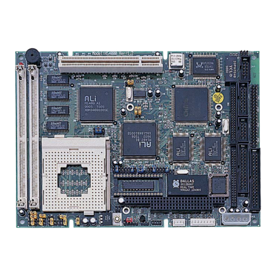
2.3 HS-4000’s Layout... -
Page 12: Quick Listing Of Jumpers
2.4 Quick Listing of Jumpers JP1, 2, 3, 4, 5, 7, 8, 9, 10 for CPU type setting — — for AMD CPU type selection JP11, 12 for Cache size setting — JP13 — CPU clock selection JP14 for DiskOnChip™ address setting —... - Page 13 CN13: COM1 CN14: COM2 CN15: COM3 CN16: COM4 CN17: FDD CONNECTOR CN18: POWER CONNECTOR CN19: ETHERNET CONNECTOR...
-
Page 14: Jumper Setting Description
2.6 Jumper Setting Description A jumper pin-set is ON as a shorted circuit with a plastic cap inserted over two pins. A jumper pin-set is OFF as a open circuit with a plastic cap inserted over one or no pin(s) between pins. The below figure 2.2 shows the examples of different jumper pin-set setting as ON or OFF in this manual. -
Page 15: Setting The Cpu Of Hs-4000
2.7 Setting the CPU of HS-4000 The HS-4000 provides all possibility in jumper setting for wide using all types of 486 series CPU with JP1, JP2, JP3, JP4, JP5, JP7, JP8, JP9 and JP10 setting as following: CPU Clock Setting JP10 1.IntelDX4™... -
Page 16: Cmos Data Clear
JP25 DESCRIPTION Clear Data *OFF Normal 2.9 Cache Size Select The HS-4000 design in with a wide ranges Cache Size architectures to meet all different costs request. The standard specification is 32K x 8. Cache Size select JP11 JP12 DESCRIPTION... -
Page 17: System Memory Dram
2.10 System Memory DRAM The HS-4000 provides a wide range on-board DRAM memory sizes from 1 MB to 16 MB by using 1, 2, 4, 8 or 16MB 72-pin SIMMs (Single In-Line Memory Modules) with access time should be 70 n-second or faster. - Page 18 JP19 : WDT Time - Out Period PERIOD *1 sec 2 sec 10 sec 20 sec 110 sec 220 sec The Watch -dog timer is disabled after the system Power-On. The watch -dog timer can be enabled by a Enable cycle with reading the control port (443H), a Refresh cycle with reading the control port (443H) and a Disable cycle by reading the Watch -dog timer disable control port (043H).
-
Page 19: Vga Controller
STN LCDs and up to 16 M co lors on 24-bit active matrix LCDs. The HS-4000 uses C&T 65550 chipset. Provides 2.0 mm pitch 44-pin on-board internal connector for flat panel connection; and a external DB15 analogy R.G.B. -
Page 20: Diskonchip? Address Setting
2.13 DiskOnChip? Address Setting The HS-4000 provides a U8 socket for install the DiskOnChip? module. A JP14 may select the starting memory address of the DiskOnChip? (D.O.C.) for avoid the mapping area with any other memory devices. If you have another extra memory devices in the system with the same memory, neither the HS-4000 nor the extra memory devices will function normally. -
Page 21: Connection
Chapter-3 Connection This chapter gives all necessary information of the peripheral's connections, switches and indicators. 3.1 The Floppy Disk Drive Connector A standard 34-pin header daisy-chain driver connector provides as CN17 with following pin assignment. Total two FDD drivers may connect. CN17 : FDD CONNECTOR PIN NO. -
Page 22: Pci E-Ide Drive Connector
3.2 PCI E-IDE Drive Connector A standard 40-pin header daisy-chain driver connector provides as CN9 with following pin assignment. Total two IDE (Integrated Device Electronics) drivers may connect. CN9(IDE 1) : Primary IDE Connector PIN NO. DESCRIPTION PIN NO. DESCRIPTION RESET GROUND DATA 7... -
Page 23: Parallel Port Connector
3.3 Parallel Port Connector A standard 26-pin flat cable driver connector provides as CN12 with following pin assignment for connection to parallel printer. CN12 : Parallel Port Connector PIN NO. DESCRIPTION PIN NO. DESCRIPTION STROBE DATA 0 DATA 1 DATA 2 DATA 3 DATA 4 DATA 5... -
Page 24: Serial Ports Connectors
3.4 Serial Ports Connectors The HS-4000's CN13, 14, 15 and 16 headers provides four high speeds NS16C550 compatible UARTs with Read/Receive 16 byte FIFO serial ports. Please see the following pin assignment. With the delivery package, user may uses the 40-pin COM cable for plug into CN13, 14, 15 and 16 for get COM1 to COM4 connection. - Page 25 The HS-4000 also provides for user in select to using the COM4 as an RS422/485. The CN16 for uses as an RS232, the CN11 for uses as an RS422 or RS485. Please reference to the following for setting the JP22 & JP23 at disable and JP24 at enable if uses as RS232 at CN16.
-
Page 26: Keyboard & Mouse Connector
3.5 Keyboard & Mouse Connector The HS-4000 provides a 8-pin header connector CN7 for connection to Keyboard & Mouse devices. CN7 : 8-pin Header Keyboard Connector PIN NO. DESCRIPTION PIN NO. DESCRIPTION MS-DATA MS-CLK KB-DATA KB-CLK 3.6 Power's LED, FAN and Key-Lock Connectors The CN1 provides both Power's LED and Key-Lock connector as following pin assignment. -
Page 27: Dc Main And Aux. Power Connectors
DESCRIPTION -12V GROUND GROUND 3.8 External Front Panel Connector The HS-4000 has an on-board buzzer. With CN3, it allows user in connection to a external speaker, IDE’s LED and Reset bottom. CN3 : Front Panel Connector PIN NO. DESCRIPTION PIN NO. -
Page 28: Ps/2 Mouse Irq12 Selection Connector
3.9 PS/2 Mouse IRQ12 Selection Connector The HS-4000 has an on-bard PS/2 mouse which using IRQ12. If you do not use the PS/2 mouse and wish to assign IRQ12 for other purposes, you should setting the JP20 to disconnect PS/2 interrupt from IRQ12. -
Page 29: Fast Ethernet Connector
LED 2 3.12 PC/104 Bus Connection The HS-4000’s PC/104 expansion bus provides you in connect to all kind PC/104 modules connection. The PC/104 bus has already become the industrial embedded 16-bit PC standard bus, so you can easily install to over thousands of PC/104 modules from hundreds of venders in the world. - Page 30 CN4&CN5 : PC/104 Expansion Bus (CN4 = 64-pin female connector; CN5 = 40-pin female connector.) RowA RowB RowC RowD IOCHECK* SBHE* MEMCS16* RESETDRV LA23 IOSC16* LA22 IRQ10 IRQ9 LA21 IRQ11 LA20 IRQ12 DRQ2 LA19 IRQ15 -12V LA18 IRQ14 NOWS* LA17 DACK0* +12V MEMR* DRQ0...
-
Page 31: Flat-Panel Connector
3.13 Flat-Panel Connector The HS-4000 provides a 44-pin 2.0 mm pitch header connector (CN8) for Flat panel connection. The information here also provides some pin information samples to Panel Sharp LM64183P, LM64C35P & LM64C142 and NEC NL8060AC26. +12V +12V FPVee... -
Page 32: Connections For Four Standard Lcds
Connections for four standard LCDs Connections to Sharp LM64183P (640 x 480 DSTN MONO LCD) Sharp LM64P83 HS-4000 CN8 Pin name Pin name CN1-1 CN1-2 CN1-3 SHFCLK CN1-4 DISP CN1-5 CN1-6 CN1-7 -17 V (external power) CN1-8 CN1-9 CN1-10 CN1-11... - Page 33 Connections to Sharp LM64C35P (640 x 480 DSTN Stn Color) Sharp LM64C35P HS-4000 CN8 Pin name Pin name CN1-1 CN1-2 CN1-3 CN1-4 CN1-5 CN1-6 CN1-7 CN1-8 CN1-9 CN1-10 SLFCHK CN1-11 CN1-12 Vcon Contrast Adjust CN1-13 CN1-14 CN1-15 CN1-16 CN1-17 CN1-18...
- Page 35 Connections to NEC NL8060AC26 (800 x 600 TFT Color) NEC NL8060AC26 HS-4000 CN8 Pin name Pin name CN1-1 CN1-2 Dot Clock SHFCLK CN1-3 CN1-4 Hsync CN1-5 Hsync CN1-6 CN1-7 CN1-8 CN1-9 CN1-10 CN1-11 CN1-12 CN1-13 CN1-14 CN1-15 CN1-16 CN1-17 CN1-18...
- Page 36 Connections to Sharp LM64C142 (640 x 480 DSTN Stn Color) Sharp LM64C142 HS-4000 CN8 Pin name Pin name CN1-1 CN1-2 CN1-3 SHFCLK CN1-4 DISP CN1-5 PVdd CN1-6 PVss CN1-7 PVee +27 V (external power) CN1-8 CN1-9 CN1-10 CN1-11 CN1-12 CN1-13...
-
Page 37: Ami Bios Setup
Chapter-4 AMI BIOS Setup For maintain the HS-4000's basic input/output system operating, the HS-4000 is now using AMI BIOS for the system configuration and operation. The BIOS's setup program is designed to provide the maximum flexibility in configuring the system by offering various optional which allowing for select and meet all of the end-user requirements. -
Page 38: Main Menu
4.1 Main Menu Once when you enter the AMI BIOS CMOS Setup Utility, the first prompt out screen is the BIOS's Main Menu. From the Main Menu, the BIOS allow you to select from several setup functions and two exit choices. Use the arrow keys to select the demand items and press <Enter>... -
Page 39: Standard Cmos Setup
4.2 Standard CMOS Setup The Standard Setup is used for the basic hardware system configuration. The main function is for Data/Time and Floppy/Hard Disk Drive settings. Please refer to the following screen for this setup. When the IDE hard disk drive you are using is larger than 528MB, please set the HDD mode to LBA mode. -
Page 40: Advanced Cmos Setup
This advanced setup is designed for the customers to achieve the highest performance of the HS-4000 board. As for normal operations, customers don't have to change any default settings. The default setting is pre-set for most reliable operations. Please refer to the following screen for the Advanced Setup. - Page 41 Note: The default Flat Panel Display types currently are: Default BIOS Panel Types No Resolution Data Panel Type 640x480 12bit Color TFT NL6448AC30-10 (NEC) 640x480 18bit Color TFT NL6448AC33-18 (NEC) 640x480 18bit Color TFT LQ10D41(SHARP) 800x600 18bit Color TFT NL8060AC26-11(NEC) 640x480 16 bit Dual-Scan Color STN LM64C08P(SHARP)
-
Page 42: Advanced Chipset Setup
4.4 Advanced Chipset Setup The advanced chipset setup functions are mostly working for the Chipset ALI M5113. These options are used to change the Chipset’s registers. Please carefully change any default settings, otherwise the system could be unstable or may not use. -
Page 43: Power Management Setup
4.5 Power Management Setup The Power Management Setup allows user to configure the system for save energy in a most effective way while operating in a manner consistent with his own style of computer use. -
Page 44: Peripheral Setup
4.6 Peripheral Setup For completed all input and output devices (i.e. FDD Drivers, IDE Drivers, Serial Ports, IR and Parallel Port), please refer to the following example. -
Page 45: A Brief Browse Of 100 Base-T Lan Rtl-8139'Sinstallation Software
Industrial Single Board in connection to-with Novell NE2000 compatible LAN network system. The HS-4000’s design which is basing on RTL 8139 chipset with provides an RJ-45 100 base-T NE2000 compatible interface. We here provide some information on the installation for your first reference. -
Page 46: Text Files List Of Help Documents
5.1 Text files list of help documents TXT\GENERAL\DIRS.TXT TXT\GENERAL\FILES.TXT TXT\NETWARE\NETWARE.TXT TXT\NETWARE\NWODIDOS.TXT TXT\NETWARE\NW312.TXT TXT\NETWARE\NW41.TXT TXT\NETWARE\NW411.TXT TXT\NETWARE\CLIENT32.TXT TXT\IBM\IBM.TXT TXT\IBM\LANSVR23.TXT TXT\IBM\LANSVR40.TXT TXT\MS\MS.TXT TXT\MS\MSCLIENT.TXT TXT\MS\MSLANMAN.TXT TXT\MS\MSWFW310.TXT TXT\MS\MSNT.TXT TXT\MS\MSWIN95.TXT TXT\UNIX\UNIX.TXT TXT\UNIX\SCO4.TXT TXT\UNIX\SCO5.TXT TXT\OTHERS\OTHER.TXT TXT\OTHERS\PACKET.TXT TXT\OTHERS\LANTAS60.TXT 5.2 Diskette Contents Files and Dirs Description VERSION.DOC This document describes some information for this version of the RTL8139 driver disk;... -
Page 47: Files On Configuration Disk
RSET8139.EXE RSET8139 program set up the adapter's hardware configuration and running diagnostics; OEMSETUP.INF The setup file for NT3.5, NT3.51 & NT4.0; NETRTP.INF The setup file for Win95 & OSR2; \TXT This subdirectory includes all text files for instruction to install various drivers;... - Page 48 OEMSETUP.INF The setup file for NT3.5, NT3.51 & NT4.0; NETRTP.INF The setup file for Win95 & OSR2; \TXT\GENERAL DIRS.TXT All subdirectory contents about this RTL8139 driver diskette; FILES.TXT All files abstract in this RTL8139 driver diskette; \TXT\IBM Text files about IBM NOS Installation Notes : LANSVR23.TXT LANSVR40.TXT \TXT\MS...
- Page 49 RTL8139.NIF Standard NIF file for OS/2; \NDIS\DOS RTSND.DOS DOS NDIS 2.0 driver; RTL8139.NIF Extended NIF file for IBM OS/2; OEMSETUP.INF Extended NIF file for DOS LAN Requester; \NDIS\OS2\RTSND.OS2 RTSND.OS2 OS2 NDIS 2.0 driver; RTL8139.NIF Extended NIF file for IBM OS/2; \NWCLIENT\DOS RTSODI.COM ODI driver for DOS;...
-
Page 50: Installing Novell Network Drivers To Workstation For Dos Odi Client
NODE SPACE.C SPACE.H LKCFG AOF/R8E \WFW31 RTSND.DOS NDIS 2.0 driver for WfW 3.10; OEMSETUP.INF Configuration file for WfW 3.11 install; \WIN95 RTL8139.SYS NDIS 3.1 mini-port driver for Windows 95& OSR2; \WINNT RTL8139.SYS NDIS 3.1 mini-port driver for Windows NT3.5, NT3.51 5.4 Installing Novell network drivers to Workstation for DOS ODI Client Introduction:... - Page 51 FRAME Ethernet_802.2 --Specify frame type FRAME Ethernet_802.3 FRAME Ethernet_SNAP FRAME Ethernet_II NetWare DOS Requester FIRST NETWORK DRIVE = F NETWARE PROTOCOL = NDS BIND PREFERRED SERVER = NW411 Setup Procedures for NetWare 3.11/3.12 Client : Before you start with the installation process, make sure that the adapter is properly installed and configured.
-
Page 52: Server Driver For Net Ware 3.12
adapter to use with your netware client.(or you can use "EtherID") 5.5 Server Driver for NetWare 3.12 Introduction: This document describes the procedure to install the NetWare v3.12 server driver for REALTEK RTL8139 Fast Ethernet adapter. Location of Driver: \NWSERVER\312\RTSSRV.LAN Installation Procedure: Before you start with the installation process, make sure that the Novell NetWare v3.12 server is properly installed. -
Page 53: Server Driver For Net Ware 4.1
The keyword "SLOT" is provided for multiple LAN adapters in a single server by the driver RTSSRV.LAN. So, add "SLOT" in LOAD commands. For example: LOAD RTSSRV FRAME=Ethernet_802.2 NAME=LAN_A SLOT=1 BIND IPX TO LAN_A NET=11 LOAD RTSSRV FRAME=Ethernet_802.2 NAME=LAN_B SLOT=2 BIND IPX TO LAN_B NET=22 2. - Page 54 MSM.NLM ETHERTSM.NLM 2. If you can log into the server as a ADMIN , copy RTSSRV.LAN relative files from the Realtek Driver Diskette subdirectory A:\NWSERVER\41 into the NetWare 4.1 subdirectory SYSTEM of your server. (If some files exists, rename the existing files in the SYSTEM subdirectory).
-
Page 55: Server Driver For Net Ware 4.11
When binding multiple frame types to one adapter, enter a LOAD and BIND statement for each frame type. Each LOAD statement will use a different network number is required on the bind statement. You need to supply a name on each load line in order to avoid being prompted for which board to bind IPX to. -
Page 56: Client 32 For Windows 95
7. The RTSSRV.LAN driver should appear in your choice list for the 'Select a LAN Driver' field. Choose this driver to start the driver loading and binding procedure. This will allow you to load and bind all 4 frame types supported by NetWare. 8. - Page 57 A. Driver Installation Procedures on Clien32 for DOS : 1. If you have completed installed the Netware Client 32 for DOS, all you have to do is to modify STARTNET.BAT. Please see the sample STARTNET.BAT above. If not, Please follow the next step 2 - step 7. 2.
-
Page 58: Installing Ibm Network Drivers To
2. Click the "My Computer" icon in the Main Program Group. 3. Click the "Control Panel" icon from My Computer window. 4. Click the "System" icon from the Control Panel window. 5. Click the "Device Manager" item. 6. Click the "Network adapter" item from System window. 7. - Page 59 Use existing configuration information? Do you have adapter option diskettes? Are you configuring for two adapters? Do you need 802.2 interface support? Source for LSP Target for new configuration C:\LSP Make sure that the values given above are correct, then press <Enter> to store your choices.
- Page 60 3. Select "Installation and configuration". The IBM logo should appear onscreen. 4. Click <OK>. 5. Select <Advance> and press <Enter>. 6. Select "Install or Configuration this Workstation." 7. Select server type, adding a server or domain controller. The "install or remove" selections should appear.
-
Page 61: Lan Server For Os/2 4.0
Speed= 100/10 ;This keyword is used to force RTL8139 adapter ;to speed 10M or 100M mode. If not present, ;the driver will auto-detect the speed. 5.10 LAN Server for OS/2 4.0 [1]. Introduction: This document describes the procedure to install NDIS driver on DOS LAN Requester and OS/2 LAN server 4.0 for Realtek RTL8139 ethernet adapter. -
Page 62: Installing Microsoft Network Drivers To
7. The screen will display "Configure" dialog box and select "LAN adapters and protocols" then press "configure" button. 8. The screen will display "LAPS Configuration" dialog box, move highlight to "RTL8139 Fast PCI Ethernet Adapter" item in "Network Adapter" window, and select "NetBios"... -
Page 63: Microsoft Network Client For Dos
Network Client for DOS Introduction: This document describes the procedure to setup the Microsoft Network Client for DOS driver on REALTEK RTL8139 Fast PCI adapter. Location of Driver: \MSCLIENT\RTSND.DOS Sample Configuration Files: Ex1: [PROTOCOL.INI] (install creates this file) [network.setup] version=0x3110 netcard=RTL8139,1,RTL8139,1 transport=ms$ndishlp,MS$NDISHLP transport=ms$netbeui,MS$NETBEUI... - Page 64 ;when more than one adapters exist on one ; system.(must be used with 'DeviceNo' keyword) DeviceNo=@0A ;This keyword is used to designate a RTL8139 ;adapter by assigning it's PCI Device number ;when more than one adapters exist on one ; system.(must be used with 'BusNo' keyword) Speed = 100/10 ;This keyword is used to force RTL8139 adapter ;to speed 10M or 100M mode.
-
Page 65: Lan Manager Workstation / Server
5.12 LAN Manager Workstation / Server Introduction: This document describes the procedure to setup LAN Manager 2.1 Workstation/Server driver for REALTEK RTL8139 Fast PCI ethernet adapter. Location of Driver: (DOS) \MSLANMAN.DOS\DRIVERS\ETHERNET\RTL8139\RTSND.DOS (OS/2)\MSLANMAN.OS2\DRIVERS\ETHERNET\RTL8139\RTSND.OS2 Sample Configuration Files: CONFIG.SYS (for DOS will contain): DEVICE=C:\LANMAN.DOS\DRIVERS\PROTMAN\PROTMAN.DOS /I:C:\LANMAN.DOS DEVICE=C:\LANMAN.DOS\DRIVERS\ETHERNET\RTL8139\RTSND.DOS... -
Page 66: Windows For Workgroups V3.0
Speed= 100/10 ;This keyword is used to force RTL8139 adapter ;to speed 10M or 100M mode. If not present, ;the driver will auto-detect the speed. Setup driver procedures on LAN Manager workstation/server : Before you start with the installation process, make sure that the adapter is properly installed and configured. - Page 67 transport=ms$netbeui,MS$NETBEUI transport=ms$ipx,MS$IPX (Added if running NetWare) lana0=RTL8139,1,ms$netbeui lana0=RTL8139,1,ms$ipx (Added if running NetWare) [protman] DriverName=PROTMAN$ PRIORITY=MS$NETBEUI [RTL8139] ; RTL8139 RPOTOCOL.INI SAMPLE DriverName=RTSND$ EtherID=@52544C111111 ;This keyword is used to designate a RTL8139 ;adapter by assigning its ethernet ID ;when more than one adapters exist on one ;...
- Page 68 AUTOEXEC.BAT C:\WINDOWS\NET START C:\WINDOWS\MSIPX (Added if running NetWare) C:\WINDOWS\NETX (Added if running NetWare) New Windows for Workgroups Installation: 1. When installing Windows for Workgroups, you are prompted for a network driver. Select the "Unlisted or Updated Network Driver". 2. Insert the REALTEK adapter driver disk containing OEMSETUP.INF and RTSND.DOS files.
-
Page 69: Windows Wnt 3.5, 3.51, & 4.0
(a) Under DOS mode, you can modify the EtherID or BusNo+DeviceNo keyword field in file C:\WFW31\PROTOCOL.INI. (b) Or you can enter Windows for WorkGroup and follow above setup procedure step 2,then click on "Setup.." button, select "Advanced...",fill EtherID in Value item. Last step to select OK and close NETWORK SETUP. -
Page 70: Windows 95 & Osr2
10. Restarting your system you will acquire network service. NOTES: Installing Multiple LAN Adapters: Enter Windows NT and follow above setup procedure step 2,in the "Network Settings" dialog box, choose the "Configure.." button. The "Input Ethernet ID" dialog box appears and input adapter's Ethernet ID. Last step to select OK and close NETWORK SETUP. - Page 71 INSTALL : Transfer dos format to unix format setup program INFO : Used by netconfig INIT : Used by netconfig MASTER : Used by netconfig NODE : Used by netconfig RECONF : Used by netconfig REMOVE : Used by netconfig SPACE.C : Used by netconfig SYSTEM...
-
Page 72: Sco Unix 5
100 Mbps 10 Mbps auto or “ENTER” auto detect 8. Enter the internet Address of this interface, for example : 192.9.9.1 9. Enter the netmask for this interface (default 255.255.255.0). 10. Does the interface use a broadcast address of all 1's (y/n), default : y 11. - Page 73 lkcfg : Used by netconfig AOF/r8e : Used by netconfig Installing driver procedure on SCO UNIX : Before you start with the installation process, make sure that the SCO UNIX system is properly installed. Similarly, your adapter should also be properly installed in your machine.
-
Page 74: Other Ntework Of Operating System Information Of Packet Driver
5.18 Other Ntework of Operating System Information of Packet Driver Introduction: This document describes the procedure to setup the Packet driver for REALTEK RTS8139 PCI ethernet card. Location of Driver: \RTSPKT\RTSPKT.COM Sample Configuration Files: AUTOEXEC.BAT RTSPKT 0x60 Notes: 1. Load the packet driver using the software interrupt and any optional switches if required. -
Page 75: Lantastic 6.0 With Ndis Driver
My Ethernet address is 52:54:4C:29:29:AD 4. Installing Multiple LAN Adapters: If there are multiple network cards on the main board. the user run RTSPKT 0x60 directly, then the screen will display : Packet driver for RTS8139, PCI version 1.00 Copyright 1997 (c), Realtek Semiconductor Inc. - Page 76 SET LAN_CFG=C:\LANTASTI rem If LANtastic is disabled, skip everything. IF EXIST DISABLED GOTO :STARTNET_DONE @echo ===== Begin LANtastic configuration ===== PATH C:\LANTASTI;C:\LANTASTI\NW;%PATH% SET LAN_DIR=C:\LANTASTI.NET SET NWDBPATH=C:\LANTASTI\NW rem Please obtain the NETBEUI.EXE program from Microsoft LOADHIGH NETBEUI LOADHIGH AI-NDIS BIND_TO=RTSND_NIF AILANBIO @STARTNET.CFG REDIR TEST @STARTNET.CFG IF EXIST NOSHARE GOTO :NOSHARE SERVER C:\LANTASTI.NET @STARTNET.CFG...
- Page 77 DRIVERNAME = PROTMAN$ DYNAMIC = YES [RTSND_NIF] DRIVERNAME = RTSND$ Adapters=RTL8139 ;EtherID =@0123456789AB Install Realtek drivers for LANtastic 6.0 : (Using NDIS driver) The installation procedure will transfer files to a specific directory on the workstation and modify existing configuration files to fit your specific needs. The installation utility INSTALL.EXE is located on LANtastic Network Software Disk 1.
Need help?
Do you have a question about the HS-4000 and is the answer not in the manual?
Questions and answers